ST. LOUIS COUNTY PROJECT NO. AR-1518
FEDERAL PROJECT NO. STP-4900(640)


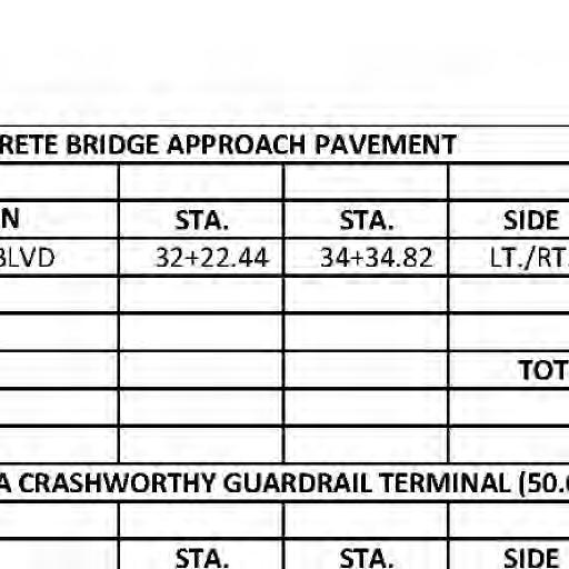
STA .34+34 .82
0 SCALE IN FEET
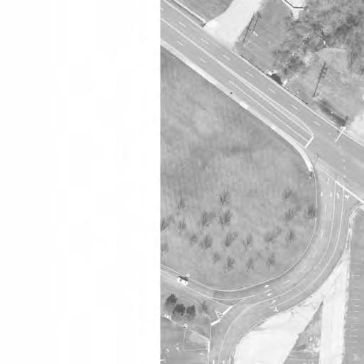
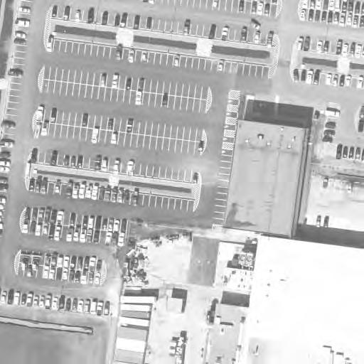
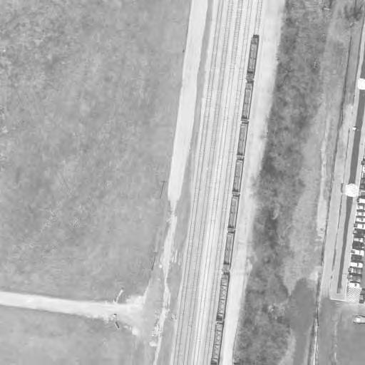
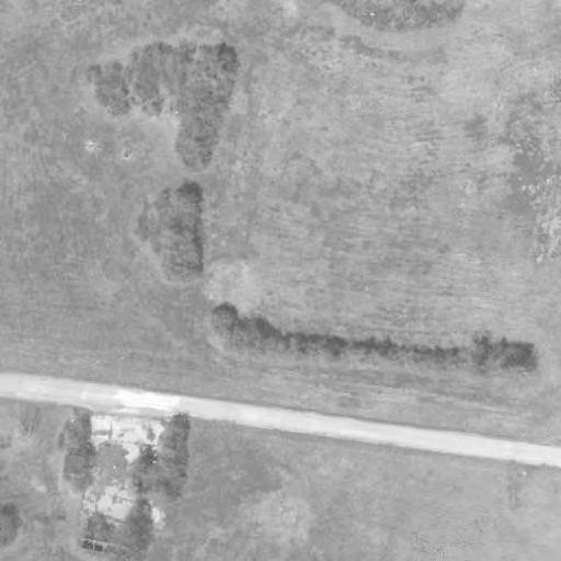
250 500 750 SCALE: 1" = 250' BOULEVARD J.S.MCDONNELL BANSHEE ROAD
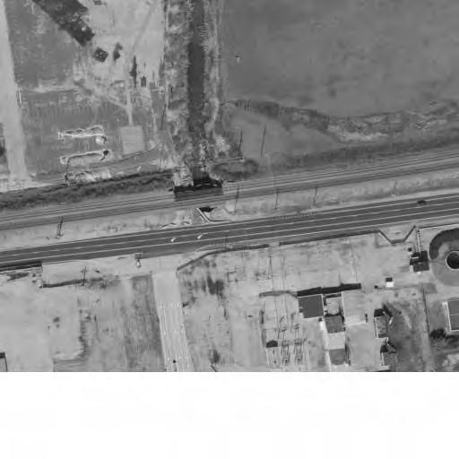
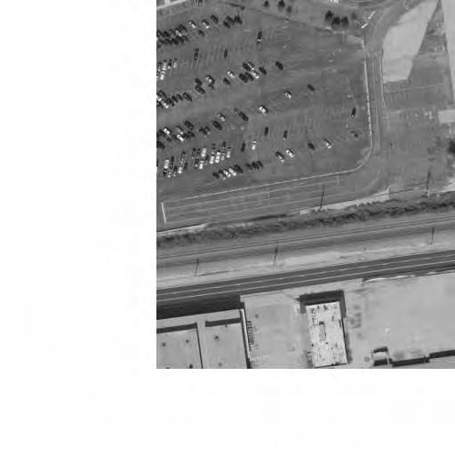
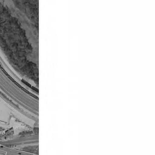
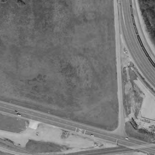
INTERCONNECT CONSTRUCTION (PHASE 3) LIMITS OF FIBER OPTIC SIGNAL (PHASE 3) (PHASE 1)AND CONSTRUCTION AND ROADWAY LIMITS OF BRIDGE LOCATION PROJECT
END PRO JECT g Director 4-26-23
WORK PHASE 2 (BY OTHERS) LIMITS OF REMEDIAL ACTION
nd a u t ho r i ze d by m y s ea l a r e do c u m e n t s i n t e R E SP ON S I B I L I T Y S C A
h i h i f t h t t h DESIGNED:

ll t h h
ny li it d by
by d i l i d
i f i ti pon i b ility f
i
20MSD-00355 N STA 28+43.57 BEGIN PRO JECT EX.R/W EX.R/W EX R/W
nd e O P U B L I C W O R K S T R AN SP O R T A T I ON
BR I DG E NO 164 J S M C DONN ELL B L VD
S


b E s ti m a t e s R e po r t s o r o t h e r D
i
nd d
f h l ting
j t d f
i


ny p
NO E2009027953 C E R T I F I C A TE O F AU T HO R I T Y S T L OU I S M O 63101 911 W A S H I NG T ON AV E S TE 620


t o b e I h STP-4900(640) 6905C-20 10K, 10L 04/11/2023 L I C E N S E NO 023795 P R O F E SS I ONA L E NG I N EE R M A RC W E S H EL M AN M.W.E. M.R.B. M.S.M. OF 63

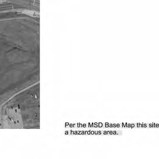
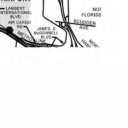
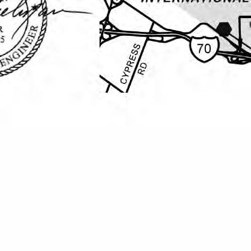
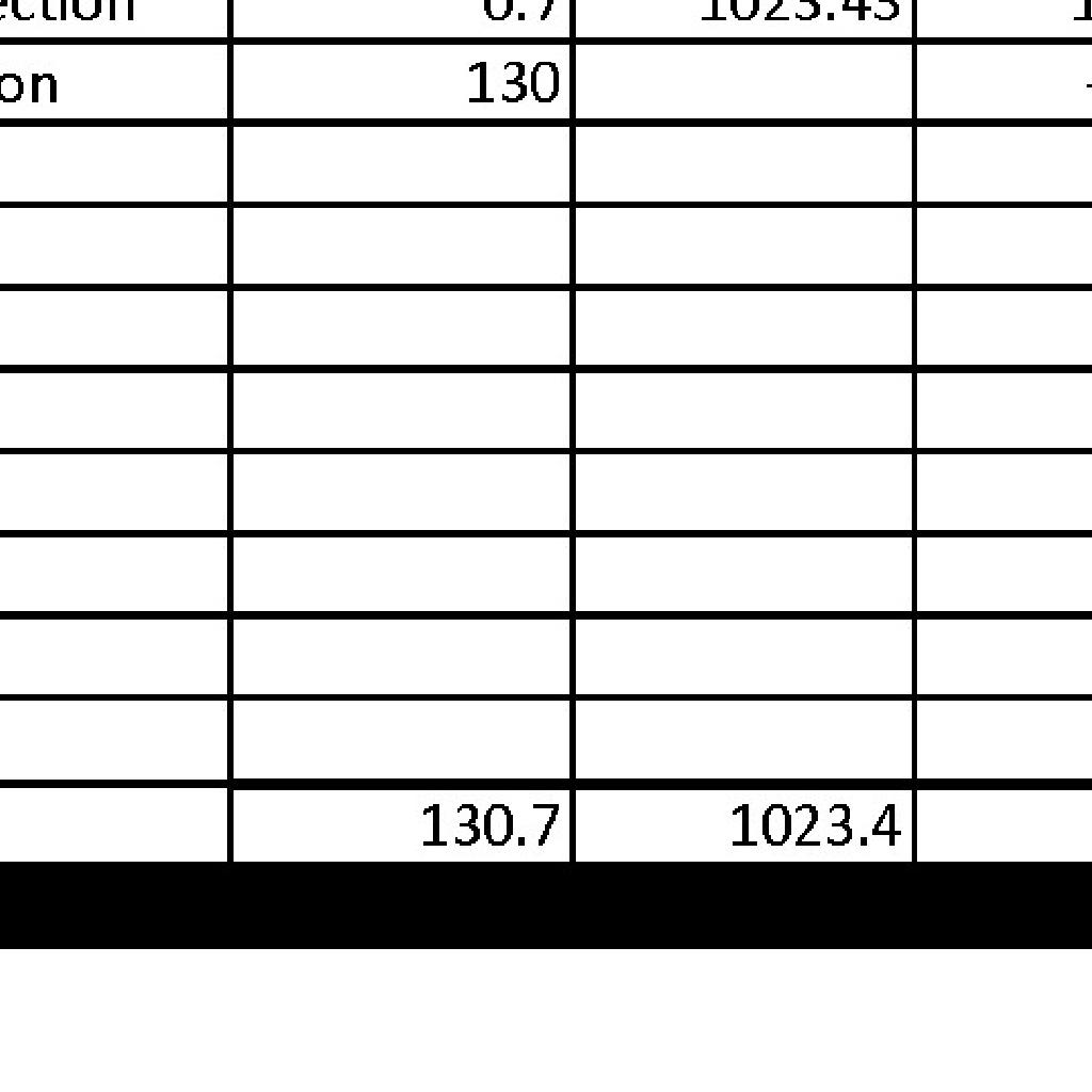
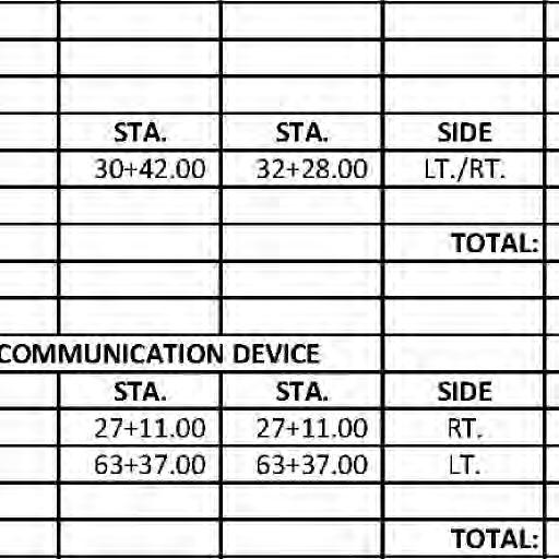
END OF PROJECT BEGINNING OF PROJECT APPARENT LENGTH EQUATIONS AND EXCEPTIONS TOTAL CORRECTIONS NET LENGTH OF PROJECT FEET FEET FEET FEET STA. STA. STATE LENGTH FEDERAL LENGTH MILES MILES FUNCTIONAL CLASSIFICATION: DESIGN YEAR: CURRENT ADT (YEAR): DESIGN ADT (YEAR): DESIGN SPEED (V) = POSTED SPEED (V) = TRUCK PERCENTAGE (T) = DIRECTIONAL DISTRIBUTION (D) = 2021 14,910 (2016) 15,820 (2028) 50% 10% 45 MPH 40 MPH PROJECT LIMITS INDEX OF SHEETS REVIEW ENGINEER: APPROVAL DATE: LENGTH OF PROJECT UTILITY NOTE THERETO. EXISTENCE AND EXACT LOCATION AND TO AVOID CONTRACTOR'S RESPONSIBILITY TO DETERMINE THEIR PRESENTLY NOT KNOWN OR SHOWN. IT IS THE THERE MAY BE OTHERS, THE EXISTENCE OF WHICH IS BE CONSIDERED APPROXIMATE ONLY. IT IS POSSIBLE RECORDS: AND, THEREFORE THEIR LOCATIONS MUST HAVE BEEN PLOTTED FROM AVAILABLE SURVEYS AND UNDERGROUND FACILITIES, STRUCTURES AND UTILITIES DESIGN CRITERIA PROPERTY LINE PERMANENT DRAINAGE EASEMENT PERMANENT SIDEWALK EASEMENT TEMPORARY SLOPE AND CONSTRUCTION LICENSE PERMANENT TRAFFIC SIGNAL EASEMENT PERMANENT FOOTING EASEMENT CONSTRUCTION LIMITS TREE OR SHRUB (DESIGNATE DIA. & TYPE) GUARDRAIL RAILROAD SIGN TO BE REMOVED TO BE ABANDONED USE IN PLACE TO BE REMOVED AND REPLACED ADJUST TO GRADE TO BE REMOVED AND REPLACED BY OTHERS TO BE ABANDONED AND FILLED ADJUST TO GRADE BY OTHERS DESCRIPTION (A.T.G.B.O.) (T.B.A.&F.) (T.B.R.&R.B.O.) (A.T.G) (T.B.R.&R.) (U.I.P.) (T.B.A.) (T.B.R.) T.S.C.L. P.T.S.E. P.R.W.E. P.D.E. PL P.S.E. MAINTENANCE AND UTILITY EASEMENT PERMANENT ROADWAY IMPROVEMENT, P.F.E. PERMANENT RETAINING WALL EASEMENT RIGHT-OF-WAY NEW RIGHT-OF-WAY EXISTING SYMBOLOGY P.R.I.M.U.E. AND SEWER EASEMENT MAINTENANCE AND UTILITY SIDEWALK PERMANENT ROADWAY IMPROVEMENT, P.R.I.M.U.S.S.E. TREE/VEGETATION LINE FENCE (DESIGNATE TYPE) W-WATER E-ELECTRIC T-TELEPHONE/CATV G-GAS UNDERGROUND UTILITY (TYPE SPECIFIED) GENERAL LEGEND LOCATOR MAP MSD CERTIFICATION P.E. SIGNED DATE THE AFOREMENTIONED FINAL MEASUREMENTS SIGNATURE AND SEAL APPLY ONLY TO IT SHOULD BE UNDERSTOOD THAT THIS PROJECT SPECIFIC INFORMATION M.S.D. P-NUMBER: M.S.D. BASE MAP: STANDARD SPECIFICATIONS PUBLIC WORKS TRANSPORTATION LOUIS COUNTY STANDARD DRAWINGS. BRIDGE CONSTRUCTION, AND BY APPLICABLE ST. COUNTY STANDARD SPECIFICATIONS FOR ROAD AND THISPROJECT SHALL BE COVERED BY THE ST. LOUIS UNLESS OTHERWISE NOTED, ALL WORK ON PRINCIPAL ARTERIAL JAMES S. MCDONNELL BOULEVARD 34+34.82 28+43.57 591.25 0 0 591.25 0.11 0.11 ST. LOUIS COUNTY BENCHMARKS 9199 9355 9466 west of McDonnell Boulevard. in the center leading from Banshee Drive to parking lot of McDonnell Douglas; 0.7 mile "L" at south end of concrete pier of railroad bridge over small divided road with the pier NAVD88(SLC2011a) Elev = 522.11 FtUS of James S. McDonnell Boulevard and 24 feet north of the centerline of Banshee Road. Boulevard onto westbound Banshee Road; roughly 32 feet southwest of the center Road), and east of the right turn lane from southeast bound James S. McDonnell north of Banshee Road, southwest of James S. McDonell Boulevard (formerly Brown "Sq" on a concrete traffic signal base situated on a triangular median island situated NAVD88(SLC2011a) Elev = 533.42 FtUS Drainage Facilities" (February 1, 2018), Section 10.080. and Regulations and Engineering Design Requirements for Sanitary Sewer and Stormwater comprehensive auto liability insurance. The requirements and limits shall be as stated in the "Rules that the permittee has obtained and will continue to carry commercial general liability and shall be required to provide the District with a copy of an executed certificate of insurance indicating Prior to obtaining a construction permit from the Metropolitan St. Louis Sewer District, the contractor McDonnell Boulevard. end of pavement rounding between the northwest edge of Byasse Drive and James S. northeasterly from the northeast edge of James S McDonnell Boulevard at the northwest Cut square on the top centerline at centerline of a 1'x8.5' concrete headwall extending NAVD88(SLC2011a) Elev = 527.72 FtUS Note: To obtain NGVD29 Datum add 0.41 FtUS to elevations shown. T I TLE AND I ND E X S H EET 20MSD-00355 10K, 10L JEFFREY MOORE ST. LOUIS, MISSOURI 63132 1050 N. LINDBERGH BLVD PROJECT DEVELOPMENT DIVISION OF TRANSPORTATION/PUBLIC WORKS DEPARTMENT OF ST. LOUIS COUNTY, MISSOURI OR PROPOSED EASEMENTS EXCEPT AS FOLLOWS: ALL PUBLIC SEWERS ARE LOCATED WITHIN DESIGNATED EXISTING RESPONSIBILITY FOR THAT SPECIFIC INFORMATION. SEWER CONTRACTOR OR OTHER SOURCES, DISCLAIM ANY HAVE BEEN PLOTTED FROM INFORMATION PROVIDED BY THE SET OF FINAL MEASUREMENT PLANS. SINCE THE WYE LOCATIONS THE RESULTS OF THOSE MEASUREMENTS ARE SHOWN ON THIS EXISTING OR PROPOSED EASEMENTS HAVE BEEN MEASURED. STRUCTURES AND SEWERS AND LOCATIONS WITH RESPECT TO THE EXISTING SEWER LENGTHS, SIZES, FLOWLINES, DEPTHS OF MSD STANDARD PLAN NOTES EXISTING CONNECTIONS: Existing water and sanitary connections will not be modified with this work. REMOVE, REPLACE, OR REHAB: remain in place, then the top shall be adjusted to grade, if needed. be determined by the MSD field inspector. If the structure is determined to The removal and replacement, or rehabilitation of the existing structure will LIMITS OF DISTURBANCE: plans and minimize disturbance within the work area wherever possible. The contractor shall stay within the limits of disturbance as shown on the added on this plan.) place at that time (including total land disturbance and/or imperviousness may require additional stormwater management per MSD regulations in Any future land disturbance and/or increase in impervious area on this site STORMWATER MANAGEMENT FUTURE DISTURBANCE: HAZARDOUS AREAS: Project Runoff Differential = 0.04 CFS Pavement Maintenance Area = 0.65 ACRES Disturbance Area = 0.90 ACRES Project Area = 1.55 ACRES UNDERGROUND TELEPHONE TO BE REMOVED BY OTHERS UT (TBRBO) STA 27+75 STA 59+80 STA 64+75 ST. LOUIS COUNTY DOT TRAFFIC CONTROL SHEETS (SHEETS 1-7 OF 7) TEMPORARY EROSION CONTROL MEASURES (SHEET 1-6 OF 6) PERMANENT CONCRETE TRAFFIC BARRIER (SHEET 1 OF 11) TEMPORARY CONTROL TRAFFIC DEVICES (SHEETS 1-8 OF 9) MIDWEST GUARDRAIL SYSTEM VERTICAL BARRIER TRANSITIONS (SHEETS 1-6 OF 6) MIDWEST GUARDRAIL SYSTEM (SHEETS 1-8 OF 8) MISSOURI DEPARTMENT OF TRANSPORTATION STANDARD SHEETS CROSS SECTIONS 56-63 BRIDGE SHEETS 13-55 EROSION CONTROL & TRAFFIC SAFETY FEATURES 12 DETOUR PLAN 11 TYPE 2 ROCK BLANKET 10 PLAN & PROFILE SHEETS 7-9 SUMMARY & SCHEDULE OF QUANTITIES 4-6 TYPICAL SECTIONS 2-3 TITLE AND INDEX SHEET 1 CONSTRUCTION PHASING NOTES APPROVED: Acting Director DATE: STA. 24+18 INTERCONNECT FROM STA 27+75 TO STA 64+75. CONSTRUCTION OF FIBER OPTIC SIGNAL APPURTENANCES FROM STATION 28+43.57 TO 34+34.82. PHASE 3 CONSTRUCTION OF BRIDGE, ROADWAY AND FILL FROM STATION 24+18 TO 59+80. TO REMOVE RADIOLOGICAL CONTAMINANTS. REPLACEMENT WITH PHASE 2 (BY OTHERS) REMOVAL OF PAVEMENT AND EXCAVATION INTERCONNECT. WIRELESS COMMUNICATION DEVICES FOR TEMPORARY SIGNAL PHASE 1 - DEMOLITION OF EXISTING BRIDGE AND INSTALLATION OF 1
APRIL 11, 2023 FEDERAL PROJECT NO. AR-1518 SHEET SEQUENCE: COUNTY PROJECT NO. E-W GATEWAY TIP NO. R E V I S I ON S R E V DA TE B Y A PP D E S CR I P T I ON MSD BASE MAP: MSD: DRAWN: DATE: CHECKED:
JAMES S. MCDONNELL BLVD. BRIDGE NO. 164 FOR THE REPLACEMENT OF CONSTRUCTION PLANS
i
20MSD-00355

h i h R E SP ON S I B I L I T Y S C A
ll t h h I
ny li it d DESIGNED:

by d i l i by
i f t h t t h BR I DG E NO 164 J S M C DONN ELL B L VD
i f i ti pon i b ility f
i
S

nd a u t ho r i ze d by m y s ea l a r e do c u m e n t s i n t e nd e d t o b e O P U B L I C W O R K S T R AN SP O R T A T I ON
b E s ti m a t e s R e po r t s o r o t h e r D
i
nd d
f h l ting
NO E2009027953 C E R T I F I C A TE O F AU T HO R I T Y S T L OU I S M O 63101 911 W A S H I NG T ON AV E S TE 620
h STP-4900(640) 6905C-20 10K, 10L 01/06/2023 L I C E N S E NO 023795 P R O F E SS I ONA L E NG I N EE R M A RC W E S H EL M AN M.W.E. M.R.B. M.S.M. OF 63
GRADE PROFILE CONST. CL 12'-0" LANE VARIES 12'-0" LANE E X R / W VARIES E X R / W SE* TACK-EMULSIFIED ASPHALT (SS-1H) PRIME LIQUID ASPHALT (MC-30) 4" TYPE 5 AGGREGATE BASE LANE 12'-0" VARIES 12'-0" LANE VAR. SHLDR MIN 3'-0" WEARING SURFACE 2" SP125 ASPHALTIC CONCRETE CONCRETE BASE 10" SP190 ASPHALTIC GRADE PROFILE CONST. CL VARIES VARIES E X R / W VARIES E X R / W SE* TACK-EMULSIFIED ASPHALT (SS-1H) PRIME LIQUID ASPHALT (MC-30) 4" TYPE 5 AGGREGATE BASE 3:1MAX WEARING SURFACE 2" SP125 ASPHALTIC CONCRETE CONCRETE BASE 10" SP190 ASPHALTIC STA. 28+43.57 TO STA. 30+51.43 VARIES VARIES VARIES VARIES VARIES VAR. SHLDR MIN 3'-0" 2 ( S H EET 1 O F 2 ) T Y P I C A L S E C T I ON S SHOULDER USE SHARED 5'-0" MIN SHOULDER USE SHARED 5'-0" MIN SE* SE* SECTION AT GUARDRAIL PAVEMENT 4:1 4:1 1'-0"** 1'-0"** **1'-0" **1'-0" LANE LH TURN MEDIAN/ PAINTED 10'-0" MAX LANE 10'-6" MIN 12'-0" MAX LANE 10'-6" MIN 12'-0" MAX LANE 10'-6" MIN 12'-0" MAX LANE 10'-6" MIN 12'-0" MAX STA. 32+43.96 TO STA. 34+34.82 * DETAILS. FOR SUPERELEVATION TRANSITION TYPICAL SECTIONS SHEET 2 OF 2, SEE SUPERELEVATION DIAGRAM, ** WHERE GUARDRAIL IS PRESENT. SEE SECTION AT GUARDRAIL 3:1MAX 3:1MAX TYPICAL SECTION - J.S. MCDONNELL BLVD TYPICAL SECTION - J.S. MCDONNELL BLVD SHOULDER CROSS SLOPE 1'-0" GRADED SHELF MATCHING FEDERAL PROJECT NO. AR-1518 SHEET SEQUENCE: COUNTY PROJECT NO. E-W GATEWAY TIP NO. R E V I S I ON S R E V DA TE B Y A PP D E S CR I P T I ON MSD BASE MAP: MSD: DRAWN: DATE: CHECKED:
i
i
j t d f
ny p
20MSD-00355


nd a u t ho r i ze d by m y s ea l a r e do c u m e n t s i n t e nd e d t o b e R E SP ON S I B I L I T Y S C A
ny li it d by
h i h DESIGNED:


by d i l i
ll t h h
i f i ti pon i b ility f
i
S


b E s ti m a t e s R e po r t s o r o t h e r D
I h O P U B L I C W O R K S T R AN SP O R T A T I ON
BR I DG E NO 164 J S M C DONN ELL B L VD

NO E2009027953 C E R T I F I C A TE O F AU T HO R I T Y S T L OU I S M O 63101 911 W A S H I NG T ON AV E S TE 620

nd d
i
f h l ting

i f t h t t h STP-4900(640) 6905C-20 10K, 10L 01/06/2023 L I C E N S E NO 023795 P R O F E SS I ONA L E NG I N EE R M A RC W E S H EL M AN M.W.E. M.R.B. M.S.M. OF 63
ny p
3 ( S H EET 2 O F 2 ) T Y P I C A L S E C T I ON S 28 + 00 00 29 + 00 00 30 + 00 00 31 + 00 00 32 + 00 00 33 + 00 00 34 + 00 00 35 + 00 00 -8.00% -7.00% -6.00% -5.00% -4.00% -3.00% -2.00% -1.00% CONSTRUCTION C STATIONL PROFILE GRADE +1.00% +2.00% +3.00% +4.00% +5.00% +6.00% +7.00% +8.00% 27 + 00 00 26 + 00 00 P C S T A 26 + 84 68 P T S T A 34 + 71 58 S T A 28 + 43 57 S T A 34 + 34 82 S T A 30 + 50 00 S T A 32 + 30 00 +1.8% RIGHT EDGE -3.8% LEFT EDGE CONTROL POINT #122 Set I.Rod N 30018.2306 E 30099.1650 EL. 523.03 REFERENCE TIE N MANHOLE SANITARY POLE SIGNAL POLE UTILITY 51.2' 14 5 ' 58.8' CONTROL POINT #123 Set I.Rod N 29978.4957 E 30155.4536 EL. 522.40 REFERENCE TIE N CONTROL POINT #125 Set I.Rod N 29990.4403 E 30192.1746 EL. 523.81 REFERENCE TIE N Set I.Rod N 29694.0233 E 30402.4368 EL. 520.01 N CONTROL POINT #130 Set I.Rod N 29855.3870 E 30717.4852 EL. 517.27 REFERENCE TIE N Set I.Rod N 29659.8136 E 30497.2272 EL. 514.57 N CONTROL POINT #124 Set I.Rod N 30002.4261 REFERENCE TIE N 7 27 POLE UTILITY 35.93' POLE UTILITY 10.12' MANHOLE SANITARY E 30173.6525 EL. 523.95 MANHOLE SANITARY 31.81' 35.08' POLE UTILITY 23.70' POLE UTILITY 40.52' POLE UTILITY 4.82 ' POLE UTILITY 37 36 POLE UTILITY 100.77' 15 .80' 17.65' MANHOLE SANITARY VALVE WATER 143 .59' MANHOLE TELEPHONE MANHOLE TELEPHONE 39.23 ' 161.24' PULLBOX TELEPHONE ROD IRON ROD IRON ROD IRON ROD IRON ROD IRON ROD IRON ROD IRON NOTE: SIGNED AND SEALED ON 6/25/19, FOR SURVEYOR'S NOTES AND OTHER SURVEY INFORMATION. SEE ST. LOUIS COUNTY "A PART OF THE RIGHT OF WAY OF J.S. MCDONNELL BOULEVARD", T T (#126) ROD IRON HEADWALL IE AT 60" PIPE FES IE AT 12" PIPE 84.30'7070' 100.77' (#131) ROD IRON **REFERENCE TIE **REFERENCE TIE **CONTROL POINT #131 **CONTROL POINT #126 ** CONTROL POINTS ARE LOCATED OUTSIDE OF PLAN AND PROFILE SHEET EXTENTS SUPERELEVATION DIAGRAM - J.S. MCDONNELL BLVD FEDERAL PROJECT NO. AR-1518 SHEET SEQUENCE: COUNTY PROJECT NO. E-W GATEWAY TIP NO. R E V I S I ON S R E V DA TE B Y A PP D E S CR I P T I ON MSD BASE MAP: MSD: DRAWN: DATE: CHECKED: i
i
j t d f
i f t h t t h R E SP ON S I B I L I T Y S C A
20MSD-00355


nd a u t ho r i ze d by m y s ea l a r e do c u m e n t s i n t e nd e d t o b e I h
h i h
ny li it d
by DESIGNED:
by d i l i
ll t h h
i f i ti pon i b ility f
i
S

b E s ti m a t e s R e po r t s o r o t h e r D
O P U B L I C W O R K S T R AN SP O R T A T I ON
BR I DG E NO 164 J S M C DONN ELL B L VD
NO E2009027953 C E R T I F I C A TE O F AU T HO R I T Y S T L OU I S M O 63101 911 W A S H I NG T ON AV E S TE 620
nd d
i
f h l ting
j t d f
STP-4900(640) 6905C-20 10K, 10L 04/11/2023 L I C E N S E NO 023795 P R O F E SS I ONA L E NG I N EE R M A RC W E S H EL M AN M.W.E. M.R.B. M.S.M. OF 63
i
ny p
4 S U MM A R Y O F QUAN T I T I E S FEDERAL PROJECT NO. AR-1518 SHEET SEQUENCE: COUNTY PROJECT NO. E-W GATEWAY TIP NO. R E V I S I ON S R E V DA TE B Y A PP D E S CR I P T I ON MSD BASE MAP: MSD: DRAWN: DATE: CHECKED:
i
i f t h t t h R E SP ON S I B I L I T Y S C A
20MSD-00355


nd a u t ho r i ze d by m y s ea l a r e do c u m e n t s i n t e nd e d t o b e I h
h i h
ny li it d
by DESIGNED:
by d i l i
ll t h h
i f i ti pon i b ility f
i
S
b E s ti m a t e s R e po r t s o r o t h e r D
O P U B L I C W O R K S T R AN SP O R T A T I ON
BR I DG E NO 164 J S M C DONN ELL B L VD
NO E2009027953 C E R T I F I C A TE O F AU T HO R I T Y S T L OU I S M O 63101 911 W A S H I NG T ON AV E S TE 620
nd d
i
f h l ting
j t d f
STP-4900(640) 6905C-20 10K, 10L 04/11/2023 L I C E N S E NO 023795 P R O F E SS I ONA L E NG I N EE R M A RC W E S H EL M AN M.W.E. M.R.B. M.S.M. OF 63
i
ny p
5 S C H E DU LE O F QUAN T I T I E S FEDERAL PROJECT NO. AR-1518 SHEET SEQUENCE: COUNTY PROJECT NO. E-W GATEWAY TIP NO. R E V I S I ON S R E V DA TE B Y A PP D E S CR I P T I ON MSD BASE MAP: MSD: DRAWN: DATE: CHECKED:
i
i f t h t t h R E SP ON S I B I L I T Y S C A
20MSD-00355


nd a u t ho r i ze d by m y s ea l a r e do c u m e n t s i n t e nd e d t o b e I h
h i h
ny li it d
by DESIGNED:

by d i l i
ll t h h
i f i ti pon i b ility f
i
S

b E s ti m a t e s R e po r t s o r o t h e r D
O P U B L I C W O R K S T R AN SP O R T A T I ON
BR I DG E NO 164 J S M C DONN ELL B L VD
NO E2009027953 C E R T I F I C A TE O F AU T HO R I T Y S T L OU I S M O 63101 911 W A S H I NG T ON AV E S TE 620
nd d
i
f h l ting
j t d f
STP-4900(640) 6905C-20 10K, 10L 04/11/2023 L I C E N S E NO 023795 P R O F E SS I ONA L E NG I N EE R M A RC W E S H EL M AN M.W.E. M.R.B. M.S.M. OF 63
i
ny p
6 QUAN T I T I E S T R A FF I C C ON T R O L FEDERAL PROJECT NO. AR-1518 SHEET SEQUENCE: COUNTY PROJECT NO. E-W GATEWAY TIP NO. R E V I S I ON S R E V DA TE B Y A PP D E S CR I P T I ON MSD BASE MAP: MSD: DRAWN: DATE: CHECKED:
i
20MSD-00355

nd a u t ho r i ze d by m y s ea l R E SP ON S I B I L I T Y S C A
by d i l i t e nd e d t o b e I
h i h i f t h t t h DESIGNED:
ll t h h a
ny li it d by
i f i ti pon i b ility f
i
S

b E s ti m a t e s R e po r t s o r o t h e r D
r e do c u m e n t s i n O P U B L I C W O R K S T R AN SP O R T A T I ON
BR I DG E NO 164 J S M C DONN ELL B L VD

NO E2009027953 C E R T I F I C A TE O F AU T HO R I T Y S T L OU I S M O 63101 911 W A S H I NG T ON AV E S TE 620
nd d
i
f h l ting
h STP-4900(640) 6905C-20 10K, 10L 01/06/2023 L I C E N S E NO 023795 P R O F E SS I ONA L E NG I N EE R M A RC W E S H EL M AN M.W.E. M.R.B. M.S.M. OF 63
ny p
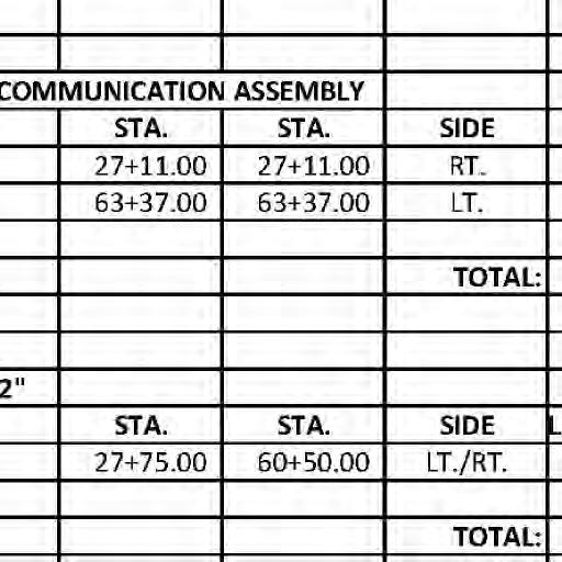
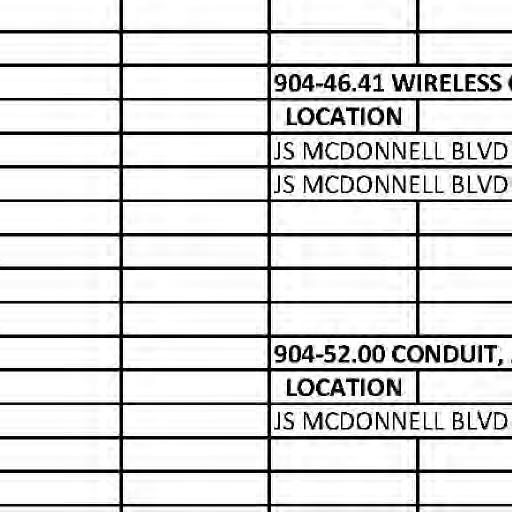
( P B IL C ) 42 RC P U POLE U POLE U POLE U POLE U POLE U POLE LIGHT ELEC.METER GUY GUY GUY GUY #B53W18SMONITOR WELL SIGNAL SIGNAL SIGNAL SCONTROL IGNAL PULL BOX CONC.WHEEL STOPS 18"VCP LOOP DETECTORS MSD BASE MAP HAZARDOUS STRUCTURE PER 10L3-016S INV (8" SE) 510.87 INV (8" NW) 510.85 TOP 522.79 SANITARY MH MSD BASE MAP HAZARDOUS STRUCTURE PER 10L3-023D INV (60" SE) 503.38 TOP 523.78 GRATE INLET 8(PUBLIC) "VCP 8 VCP (PUBLIC) 60 RCP (PUBLIC) 60 RCP (PUBLIC) M HAZARDOUS MH CONE/LID IS CONCENTRIC INV (12"E)502.94 INV (18"W)513.83 INV (42" S)501.07 INV (42" N)501.07TOP 520.83SANITARY MH (28+37) EX TELE HANDHOLE GAS VALVE WATER VALVE ASPHALT ASPHALT ASPHALT GRAVEL SIGN SIGN TELE.PEDISTAL TELE.PEDISTAL E (PUBLIC) 60" RCP (NOT SURVEYED) PULL BOX AD ELE C T R I C OVERHEAD ELECTRIC OVERHEAD ELECTRIC ASPHALT DRIVE CONC WALK ASPHALT PAVEMENT GUARD RAIL GUARD RAIL NO TAKINGS NO TAKINGS NO TAKINGS NO TAKINGS LOC.# 10L310031 BOOK 13504 PAGE 1599 142 JAMES S MCDONNELL BLVD GKN AEROSPACE NORTH AMERICA INC N/F LOC.# 10L340142 BOOK 12508 PAGE 2064 123 JAMES S MCDONNELL BLVD MIJON IV N/F 10 EASEMENT UNION ELECTRIC BOOK 15598 PAGE 796 LOC.# 10K130014 BOOK 2322 PAGE 531 111 JAMES S MCDONNELL BLVD CITY OF ST LOUIS N/F LOC.# 10L310031 BOOK 13504 PAGE 1599 142 JAMES S MCDONNELL BLVD GKN AEROSPACE NORTH AMERICA INC N/F CONSTRUCTED IMPROVEMENTS NOT ALIGN WITH THE THIS EASEMENT DOES BOOK 9593 PAGE 726 ST LOUIS COUNTY TRAFFIC SIGNAL EASEMENT 1 1 535 530 525 520 515 510 505 500 495 535 530 525 520 515 510 505 500 495 1"=20' 1"=5' 0 20 40 60 SCALE IN FEET SCALE: 1" = 20' N 27+00 28+00 29+00 30+00 27+00 28+00 29+00 30+00 M A T C H L I N E 30 + 00 M ENILHCTA +30 00 BOULEVARD
( S H EET 1 O F 3 ) P L AN AND P R O F I LE S H EET 7 CONSTRUCTION CL CURVE #1 X ST. LOUIS COUNTY FORCES. TO BE COMPLETED BY FINAL ROADWAY STRIPING 2. SHEET 3. LISTING TABLE ON REFER TO COORDINATE POINT 1. SE R T L D PT PC PI J.S. MCDONNELL BLVD. CURVE #1 6.0% 1000.00' 415.09' 786.90' 5°43' 46.5" 45°05' 10.0" (LT) 34+71.58 26+84.68 30+99.78 S52°57'50"E THERETO. EXISTENCE AND EXACT LOCATION AND TO AVOID CONTRACTOR'S RESPONSIBILITY TO DETERMINE THEIR PRESENTLY NOT KNOWN OR SHOWN. IT IS THE THERE MAY BE OTHERS, THE EXISTENCE OF WHICH IS CONSIDERED APPROXIMATE ONLY. IT IS POSSIBLE RECORDS: AND, THEREFORE THEIR LOCATIONS MUST BE HAVE BEEN PLOTTED FROM AVAILABLE SURVEYS AND UNDERGROUND FACILITIES, STRUCTURES AND UTILITIES EX R/W EX.R/W EX. R/W PC STA. 26+84.68 j j j j #123 CP #125 CP #124 CP #122 CP (U.I.P.) (T.B.R.B.O.) (AT.GB.O) (U.I.P.) ADD 1-F.O.C. (48 FIBERS) IN EX CONDUIT REMOVE EX F.O.C. (36 FIBERS) AND DIRECTED BY THE ENGINEER TERMINATE AND/OR FUSION SPLICE F.O.C. AS 1 STA. 28+43.57 BEGIN PROJECT (48 FIBERS) IN 2" CONDUIT 2-2c#18(S), 1-F.O.C. (T.B.R.B.O) (U.I.P.) BRIDGE CONSTRUCTION LIMITS IN EX CONDUIT (PHASE 3) AND ADD 1-F.O.C. (48 FIBERS) REMOVE EX F.O.C. (36 FIBERS) ONTO EXISTING MAST ARM (PHASE 1) FOR TEMPORARY SIGNAL INTERCONNECT INSTALL WIRELESS COMMUNICATION DEVICES (PHASE 3) PAVEMENT MATCH EXISTING (PHASE 2) EX 2" CONDUIT T.B.R.B.O. 27+00 28+00 29+00 30+00 ELE V 525 17 V P C 28 + 47 32 ( A C S NG ) ELE V 525 09 S T A 28 43 57 B E G I N N E W P AV E M E N T 480.00' V.C. K = 154 523 83 523 73 523 65 523 59 523 66 523 74 523 91 524 10 524 56 525 01 525 34 525 64 525 93 526 12 526 31 526 45 526 57 526 68 525 41 525 78 526 13 526 45 526 74 527 01 527 25 527 46 (PHASE 1) GRADE EXISTING PROFILE CONDUIT (UIP) FIBER OPTIC EXISTING 2" REPLACED BY OTHERS (PHASE 2) PAVEMENT TO BE REMOVED AND GRADE (PHASE 3) PROPOSED PROFILE (PHASE 3) PROFILE GRADE EXISTING S T A 27 83 FEDERAL PROJECT NO. AR-1518 SHEET SEQUENCE: COUNTY PROJECT NO. E-W GATEWAY TIP NO. R E V I S I ON S R E V DA TE B Y A PP D E S CR I P T I ON MSD BASE MAP: MSD: DRAWN: DATE: CHECKED:
J.S.MCDONNELL
i
i
j t d f
20MSD-00355

nd a u t ho r i ze d by m y s ea l a r e do c u m e n t s i n t e nd e d t o b e R E SP ON S I B I L I T Y S C A
h i h DESIGNED:

by BR I DG E NO 164 J S M C DONN ELL B L VD
ny li it d
by d i l i
ll t h h
i f i ti pon i b ility f
b E s ti m a t e s R e po r t s o r o t h e r D
i f t h t t h NO E2009027953 C E R T I F I C A TE O F AU T HO R I T Y S T L OU I S M O 63101 911 W A S H I NG T ON AV E S TE 620
I O P U B L I C W O R K S T R AN SP O R T A T I ON
i
nd d
i
S

f h l ting
j t d f
h STP-4900(640) 6905C-20 10K, 10L 06/14/2023 L I C E N S E NO 023795 P R O F E SS I ONA L E NG I N EE R M A RC W E S H EL M AN M.W.E. M.R.B. M.S.M. OF 63
i
ny p
(PUBLIC) 42 " RCP TELE MH ELEC PULL BOX & TELESIGN.MH (PUBLIC) VCP 8" PULL BOX PULL BOX PULL BOX GUARD RAIL MATURE TREES DENSE BRUSH & MATURE TREES DENSE BRUSH & MATURE TREES DENSE BRUSH & MATURE TREES DENSE BRUSH & A B OV E G R OUND ( U S R A ) 4 HD E ABOVE GROUND (FUSRAP) 4"HDPE LOOP DETECTORS 42 RCP (PUBLIC) 42 " RCP (PUBLIC) MSD BASE MAP HAZARDOUS STRUCTURE PER 10L3-066S INV (8" E) 503.33 DROP INV (8" W) 503.39 INV (8" W) 507.60 TOP 518.93 SANITARY MH BURIED SHEET PILE WALL (FUSRAP) HANDHO(30+90) LE EX TELEPHONE HANDHO(31+90) LE EX TELEPHONE GAS VALVE SLOPERPROTECTION IP RAP SLOPERPROTECTION IP RAP SLOPERPROTECTION IP RAP SIGN SIGN PROTECTION RSLOPE IP RAP 34" TREE 6 WIDE CONC ENCASEMENT EE (PUBLIC) 60" RCP T T GUARD RAIL ATTACHED TO BRIDGE 4 HDPE PRESSURE SEWER ASPHALT PAVEMENT CONCRETE BRIDGE DECK GUARD RAIL GUARD RAIL ATTACHED TO BRIDGE CONDUIT 2 STEEL TREE 8"x3" NO TAKINGS NO TAKINGS NO TAKINGS LOC.# 10K110021 BOOK 2322 PAGE 531 101 JAMES S MCDONNELL BLVD CITY OF ST LOUIS N/F LOC.# 10K130014 BOOK 2322 PAGE 531 111 JAMES S MCDONNELL BLVD CITY OF ST LOUIS N/F STATE OF MISSOURIBOOK 2853 PAGE 421 100 WIDE DRAINAGE EASEMENT COLD WATER CREEK DRAINAGE LOC.# 10K110030 BOOK 6666 PAGE 541 110 JAMES S MCDONNELL BLVD ST LOUIS AIRPORT AUTHORITY N/F 2 535 530 525 520 515 510 505 500 495 535 530 525 520 515 510 505 500 495 1"=20' 1"=5' 31+00 32+00 33+00 34+00 M A T C H L I N E 30 + 00 M A TC H LI N E 30 + 00
30+00 35+00 30+00 31+00 32+00 33+00 34+00 35+00 ( S H EET 2 O F 3 ) P L AN AND P R O F I LE S H EET L CONSTRUCTION C CURVE #1 0 20 40 60 SCALE IN FEET SCALE: 1" = 20' X ST. LOUIS COUNTY FORCES. TO BE COMPLETED BY FINAL ROADWAY STRIPING 2. SHEET 3. LISTING TABLE ON REFER TO COORDINATE POINT 1. SE R T L D PT PC PI J.S. MCDONNELL BLVD. CURVE #1 6.0% 1000.00' 415.09' 786.90' 5°43' 46.5" 45°05' 10.0" (LT) 34+71.58 26+84.68 30+99.78
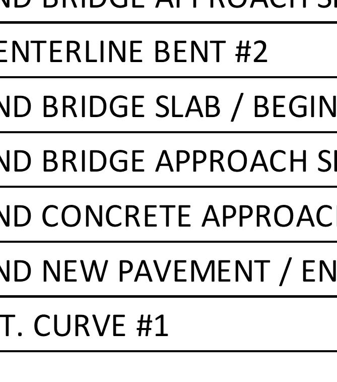
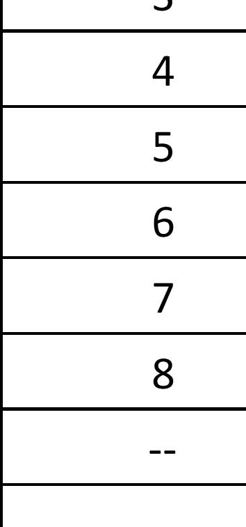
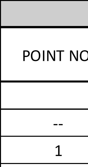
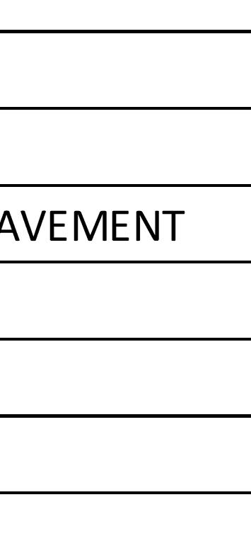
AND TO AVOID THERETO. EXISTENCE AND EXACT LOCATION RESPONSIBILITY TO DETERMINE THEIR KNOWN OR SHOWN. IT IS THE CONTRACTOR'S THE EXISTENCE OF WHICH IS PRESENTLY NOT ONLY. IT IS POSSIBLE THERE MAY BE OTHERS, LOCATIONS MUST BE CONSIDERED APPROXIMATE SURVEYS AND RECORDS: AND, THEREFORE THEIR UTILITIES HAVE BEEN PLOTTED FROM AVAILABLE UNDERGROUND FACILITIES, STRUCTURES AND EX R/W EX.R/W EX.R/W PT STA. 34+71.58 8 STA. 34+34.82 END PROJECT 2 3 5 6 4 CRE E K COLDW ATE R CR EE K COLDW ATE R j #130 CP (UI.P.) (U.I.P.) (U.IP.) (TBR) (T.B.R.&R.B.O) (U.I.P.) (A.T.G.B.O) (U.I.P.) (TBR&RBO) (UI.P.) (U.IP) (T.B.R.&R.B.O) (T.B.R.BO) (U.IP) (U.IP) (TBR&RBO) ( U I. P ) (UI.P.) (T.B.R.) (TBR) (TBR) ( U I P ) N (T.B.R.) STOP LINE 279'TO 21 20 30 31 EX 2" CONDUIT T.B.R. EX 2" CONDUIT T.B.R. IN 2" CONDUIT (48 FIBERS) 1-F.O.C. 2-2c#18(S), 1-F.O.C. (48 FIBERS) IN 2" CONDUIT PER C904.70 INSIDE OF EOP ONE FOOT CONDUIT BEGIN 1" IN SAWED SLOT, TUBE JACKET 2-1c#14 W/ INDUCTION LOOP DETECTOR SCHEDULE 20 21 NO. LOOP STANDARD (3-TURNS) IN RACK CARD POSITION USED CHANNEL 2 A B STANDARD (3-TURNS) 6' X 6' 2 PULL BOX SCHEDULE BOX NUMBER 31 30 BOX TYPE AND DIMENSIONS 17" W X 30" L X 26" MIN. H W/ CONC. APRON PLASTIC MORTAR REINFORCED 7 PER C904.70 ONE FOOT INSIDE OF EOP IN SAWED SLOT, BEGIN 1" CONDUIT 2-1c#14 W/ TUBE JACKET FOR CONDUIT IN BARRIER CURB SEE STRUCTURAL DETAIL 1-2" CONDUIT (EMPTY) 1-F.O.C. (48 FIBERS) IN 2" CONDUIT (TBRB.O) (T.B.R.) (A.T.G.BO) M ATCHLINE 35+ 00 8 BRIDGE CONSTRUCTION LIMITS PAVEMENT (PHASE 3) MATCH EXISTING 30 31 31+00 32+00 33+00 34+00 35+00 30+00 ELE V 529 97 V P I 30 87 32 ( M A T C H E X I S T I NG ) ELE V 526 08 S T A 34 34 82 E ND N E W P AV E M E N T +200% -112% ELE V 527 28 V P T 33 + 27 32 480.00' V.C. K = 154 526 68 526 76 526 93 527 03 526 95 526 98 527 01 527 00 527 00 526 98 526 96 526 93 526 85 526 83 526 82 526 79 526 74 526 69 526 62 526 53 526 39 526 20 526 02 525 80 525 59 527 46 527 65 527 81 527 95 528 06 528 15 528 20 528 24 528 24 528 23 528 18 528 11 528 01 527 89 527 74 527 57 527 36 PIPE BEDDING (U.I.P) ELEV. 501.01 APPROX. FL. 527 14 526 92 526 70 526 47 526 25 ELE V 513 73 S T A 31 + 85 24 R T D I T C H B E G I N P R O P O S E D ELE V 514 00 S T A 32 + 57 83 R T D I T C H E ND P R O P O S E D (PHASE 3) PROFILE GRADE EXISTING GRADE (PHASE 3) PROPOSED PROFILE GRADE (PHASE 1) EXISTING PROFILE REPLACED BY OTHERS (PHASE 2) PAVEMENT TO BE REMOVED AND S T A 34 + 56 S T A 31 37 C E N TE R L I N E B E N T #2 SEWER (U.I.P) SANITARY 42" RCP FEDERAL PROJECT NO. AR-1518 SHEET SEQUENCE: COUNTY PROJECT NO. E-W GATEWAY TIP NO. R E V I S I ON S R E V DA TE B Y A PP D E S CR I P T I ON MSD BASE MAP: MSD: DRAWN: DATE: CHECKED:
BOULEVARD J.S.MCDONNELL
N81°57'00"E
i
by R E SP ON S I B I L I T Y S C A
h i h
ny li it d
nd a u t ho r i ze d by m y s ea l a r e do c u m e n t s i n t e nd e d t o b e I h DESIGNED:

by d i l i
ll t h h
i f i ti pon i b ility f
i
20MSD-00355 M AT C H LI N E 35 + 00


i f t h t t h O P U B L I C W O R K S T R AN SP O R T A T I ON
BR I DG E NO 164 J S M C DONN ELL B L VD
S
b E s ti m a t e s R e po r t s o r o t h e r D
i
nd d
f h l ting
j t d f
i
i

ny p
NO E2009027953 C E R T I F I C A TE O F AU T HO R I T Y S T L OU I S M O 63101 911 W A S H I NG T ON AV E S TE 620


STP-4900(640) 6905C-20 10K, 10L 01/06/2023 L I C E N S E NO 023795 P R O F E SS I ONA L E NG I N EE R M A RC W E S H EL M AN M.W.E. M.R.B. M.S.M. OF 63


N BOULEVARD J.S.MCDONNELL
PULL BOX SCHEDULE BOX NUMBER 33 32 BOX TYPE AND DIMENSIONS 17" W X 30" L X 26" MIN. H W/ CONC. APRON PLASTIC MORTAR REINFORCED 35 34 37 36 33 35 34 36 0 150' 300' 450' SCALE IN FEET SCALE: 1" = 150' 32 ROADWAY CL 9 ( S H EET 3 O F 3 ) P L AN AND P R O F I LE S H EET 37 400' 400' 400' 400' 400' 1 - FIBEROPTIC CABLE (48 FIBERS) IN 2" CONDUIT (PHASE 3) EXISTING CONDUIT T.B.R.B.O. (PHASE 2) EXISTING MAST ARM (PHASE 1) INTERCONNECT ONTO TEMPORARY SIGNAL COMMUNICATION DEVICES FOR INSTALL WIRELESS E VA AV E NU E T.B.R.B.O. (PHASE 2) EXISTING PULL BOX T.B.R.B.O. (PHASE 2) EXISTING PULL BOX EXISTING PULL BOX T.B.R.B.O. (PHASE 2) EXISTING PULL BOX T.B.R.B.O. (PHASE 2) EXISTING PULL BOX T.B.R.B.O. (PHASE 2) T.B.R.B.O. (PHASE 2) EXISTING PULL BOX IN EX CONDUIT (PHASE 3) AND ADD 1-F.O.C. (48 FIBERS) REMOVE EX F.O.C. (36 FIBERS) EXISTING PULL BOX (UIP) EXISTING PULL BOX (UIP) 36 + 00 37 + 00 38 + 00 39 + 00 40 + 00 41 + 00 42 + 00 43 00 44 + 00 45+ 00 46+ 00 47+ 00 48+ 00 49+ 00 50+ 00 51+ 00 52+ 00 53+ 00 54+ 00 55+ 00 56+ 00 57+ 00 58+ 00 59+ 00 60+ 00 61+ 00 62+ 00 63+ 00 64+ 00 65+ 00 FEDERAL PROJECT NO. AR-1518 SHEET SEQUENCE: COUNTY PROJECT NO. E-W GATEWAY TIP NO. R E V I S I ON S R E V DA TE B Y A PP D E S CR I P T I ON MSD BASE MAP: MSD: DRAWN: DATE: CHECKED:
BANSHEE ROAD
205
519 5 06 50 7 5 0 8 5 0 9 5 10 5 11 5 12 5 13 5 14 5 15 5 16 5 17 5 18 519 52 0 52 1 52 2 52 3 52 4

035 505 507 508 509
5 0 6 5 0 7 508 50 9 510 511 5 21 5 31 5 14 5 51 516 751 851 5 19 5 2 0 52 1 5 22 523 52 4
510 511 512 513 514 519

i f t h t R E SP ON S I B I L I T Y S C A
20MSD-00355
nd a u t ho r i ze d by m y s ea l a r e do c u m e n t s i n t e nd e d t o b e I h
h i h
ny li it d
by DESIGNED:

by d i l i
ll t h h
i f i ti pon i b ility f
i
S
b E s ti m a t e s R e po r t s o r o t h e r D
t h O P U B L I C W O R K S T R AN SP O R T A T I ON
BR I DG E NO 164 J S M C DONN ELL B L VD
NO E2009027953 C E R T I F I C A TE O F AU T HO R I T Y S T L OU I S M O 63101 911 W A S H I NG T ON AV E S TE 620
nd d
i
f h l ting
j t d f
STP-4900(640) 6905C-20 10K, 10L 01/06/2023 L I C E N S E NO 023795 P R O F E SS I ONA L E NG I N EE R M A RC W E S H EL M AN M.W.E. M.R.B. M.S.M. OF 63
i
ny p
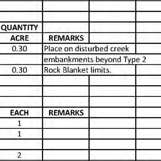
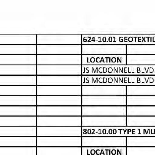
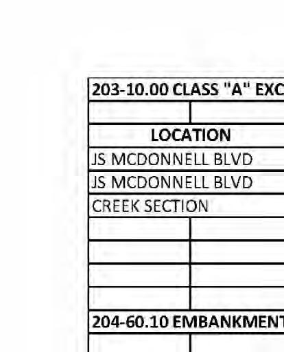
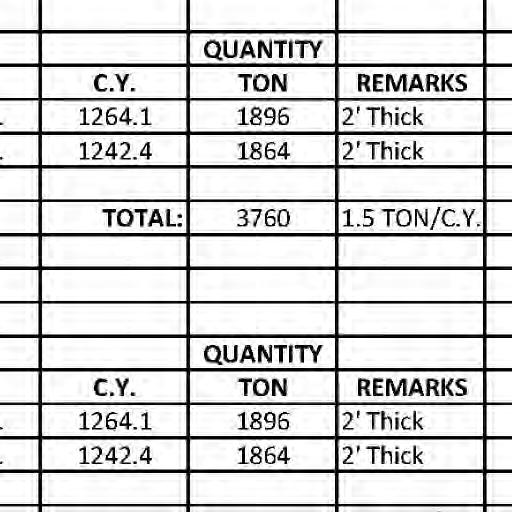
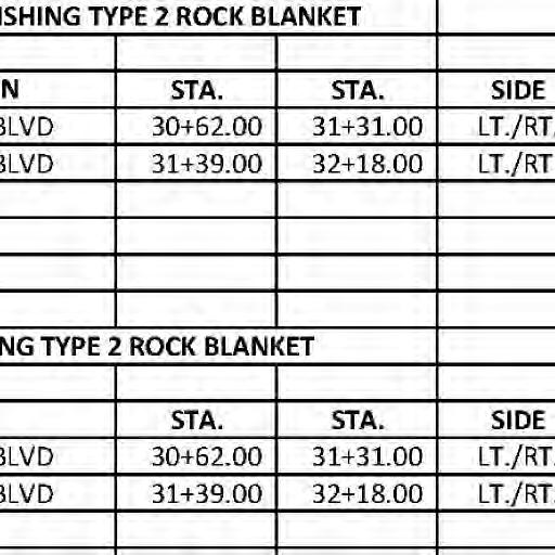
N 10 1. 2. 3. 4. EMBANKMENT PROTECTION NOTES COORPERATION WITH UTILITY COMPANIES. THE CONTRACTOR SHALL COORDINATE THEIR ACTIVITIES IN EXISTENCE AND EXACT LOCATION, AND TO AVOID THERETO. CONTRACTOR'S RESPONSIBILITY TO DETERMINE THEIR WHICH ARE NOT KNOWN OR SHOWN. IT IS THE APPROXIMATE. THERE MAY BE OTHER FACILITIES PRESENT RECORDS, AND THEIR LOCATIONS SHOULD BE CONSIDERED HAVE BEEN PLOTTED FROM AVAILABLE SURVEYS AND UNDERGROUND FACILITIES, STRUCTURES, AND UTILITIES SEE ROADWAY PLAN SHEET FOR UTILITY INFORMATION. DIRECTED BY THE ENGINEER. ADJUSTED IN THE FIELD TO SUIT GROUND CONDITIONS AS AND EXCAVATION. LAYOUT OF ROCK BLANKET MAY BE VERIFIED AND DETERMINED PRIOR TO MATERIAL PURCHASING ALL DIMENSIONS ARE APPROXIMATE AND SHALL BE FIELD THE BOTTOM OF ALL GIRDERS. MINIMUM OF ONE FOOT OF VERTICAL CLEARANCE FROM OF COVER OVER THE BOTTOM OF CONCRETE AND A AT EACH END BENT TO ENSURE A MINIMUM OF TWO FEET GRADING SHALL BE ADJUSTED IN THE FIELD AS NEEDED 0 10 20 30 SCALE IN FEET SCALE: 1" = 10' TYPE 2 ROCK BLANKET NEAR BRIDGE TYPE 2 ROCK BLANKET DETAIL OF ROCK BLANKET AFTER PLACEMENT STREAMBED MATERIAL FILL WITH NATURAL EXISTING CREEK FLOWLINE TOE WALL AROUND PERIMETER. TYP.) (INCLUDES A 2' X 2.5' DEEP WITH GEOTEXTILE FABRIC 2' THICK TYPE 2 ROCK BLANKET LEGEND SLOPE AT TOE OF EXACAVATION GEOTEXTILE EROSION CONTROL PERMANENT (N.T.S) TYPE 2 THIS SHEET) (SEE LEGEND ON ROCK BLANKET 1'-0" 4 ( M I N ) BURIED ROCK BLANKET CONSTRUCTION CL 28' LT +29 24' LT +24 32' LT +21 28' LT +16 52' LT +79 37' LT +64 26' LT +57 32' LT +52 36' LT +60 28' LT +65 46' LT +84 50' LT +18 42' RT +70 30' RT +56 27' RT +49 40' RT +48 40' RT +39 59' RT +31 58' RT +22 54' RT +98 45' RT +75 30' RT +10 29' RT +18 38' RT +62 81' RT +05 69' RT +84 END BENT 1 FILL FACE END BENT 3 FILL FACE 1'-0" T Y P E 2 R O C K B L ANK ET 31+00 32+00 FEDERAL PROJECT NO. AR-1518 SHEET SEQUENCE: COUNTY PROJECT NO. E-W GATEWAY TIP NO. R E V I S I ON S R E V DA TE B Y A PP D E S CR I P T I ON MSD BASE MAP: MSD: DRAWN: DATE: CHECKED:
i
M04-9P J S MCDONNELL BLVD MO4-9R
M04-9P J S MCDONNELL BLVD 0.5 MO4-9R MO4-9L

R11-3a
ROAD CLOSED TO R11-4
ENTRANCE TO GKN
THRU TRAFFIC R11-2
M04-9P J S MCDONNELL BLVD
MO4-9L
M04-9P J S MCDONNELL BLVD 0.1
CLOSED
M04-9P J S MCDONNELL BLVD
M04-9P J S MCDONNELL BLVD MO4-9L
ROAD MO4-9R
NEXT SHEET WORK AREA SEE SEE NOTE 10 ABOVE
i f t h t t h BR I DG E NO 164 J S M C DONN ELL B L VD
ny li it d DESIGNED:

h i h R E SP ON S I B I L I T Y S C A
by d i l i by
ll t h h
i f i ti pon i b ility f
i
S
nd a u t ho r i ze d by m y s ea l a r e do c u m e n t s i n t e nd e d t o b e O P U B L I C W O R K S T R AN SP O R T A T I ON
b E s ti m a t e s R e po r t s o r o t h e r D
20MSD-00355 R11-3a
i
nd d
f h l ting
ny p
NO E2009027953 C E R T I F I C A TE O F AU T HO R I T Y S T L OU I S M O 63101 911 W A S H I NG T ON AV E S TE 620
I h STP-4900(640) 6905C-20 10K, 10L 04/11/2023 L I C E N S E NO 023795 P R O F E SS I ONA L E NG I N EE R M A RC W E S H EL M AN M.W.E. M.R.B. M.S.M. OF 63
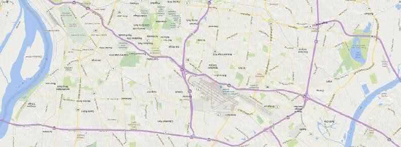
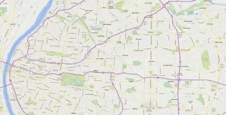
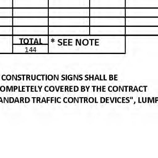
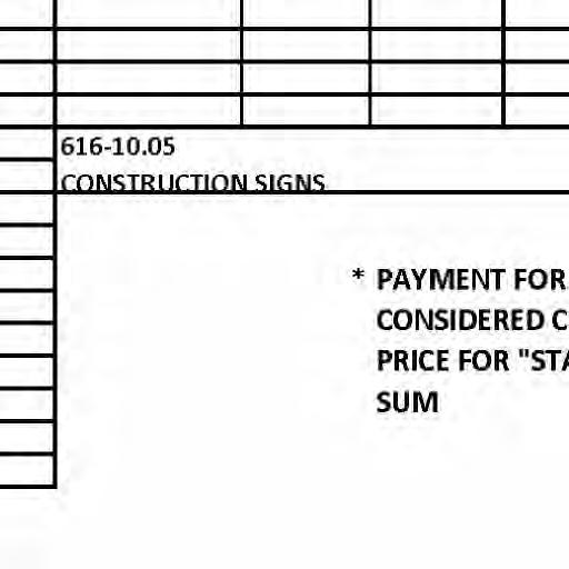
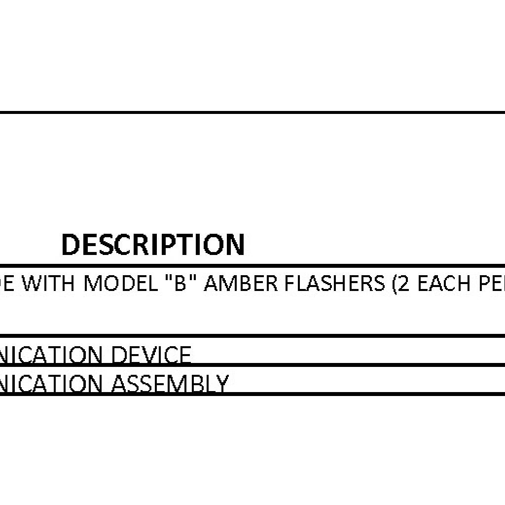
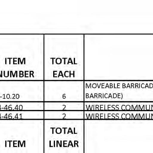
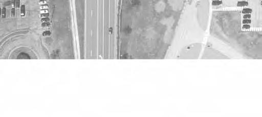
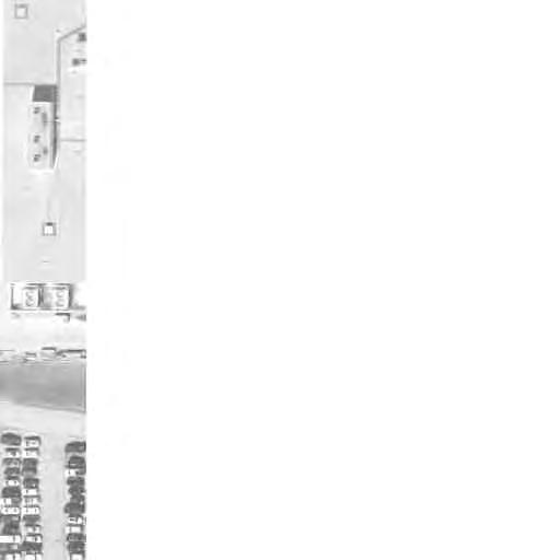
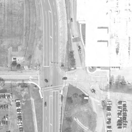
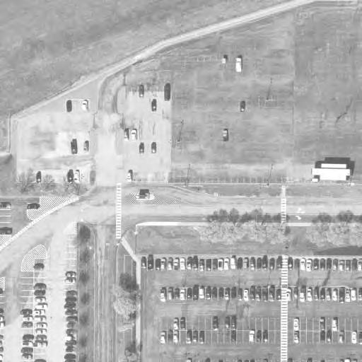
D ET OU R P L AN 11 N 0 SCALE IN FEET SCALE: 1" = 500' 500 1,000 1,500 CHANNELIZER CONE CHANGEABLE MESSAGE CONTRACTOR RETAINED SIGN, CONTRACTOR FURNISHED, TRAFFIC CONTROL LEGEND TRAFFIC CONTROL NOTES: SIGN (SINGLE SIDED) FLAGGER SIGN (DOUBLE SIDED) FLASHERS (2 EACH PER BARRICADE) MOVEABLE BARRICADE W/ MODEL "B" AMBER right of way. All traffic control devices and detour signage shall be placed outside railroad 10. price for "Standard Traffic Control Devices". item shall be considered completely covered by the Lump Sum contract unit Cost of all Traffic Control Devices not otherwise covered by a separate pay 9. one-half at a time to allow traffic access if necessary. in accordance with the Job Special Provisions. Driveways shall be constructed Contractor shall maintain access to private properties adjacent to work area 8. Lump Sum contract unit price for "Standard Traffic Control Devices". covered by a separate pay item shall be considered completely covered by the C612.10 "Traffic Control Devices." Cost of all Traffic Control Devices not otherwise duration of the project and shall be mounted as shown on the Standard Drawing Contractor furnished signs shall be maintained and kept clean for the 7. See Traffic control Plans for Construction Sign Schedule. 6. with Engineer. Contractor shall coordinate message displayed on Changeable Message Signs 5. shall cover all existing signs that conflict with the Detour/Traffic Control Plan. Install all traffic control devices and signs prior to closing road. Contractor 4. greater visibility. Sign placement may be modified in the field by the Engineer as needed for 3. Contractor shall contact Missouri One Call (Dig-Rite) prior to installing signs. Contractor is responsible for utitily locates prior to placing sign posts. 2. Traffic Control Devices 616.10 for Traffic Control Devices, and St Louis County Standard Plan C612.10 for the Manual on Uniform Traffic Control Devices (MUTCD), MoDOT Standard Plan Traffic Control shall be furnished, installed, and maintained in accordance with 1. BANSHEE RD JAMES S MCDONNELL BLVD BYASSE RD FROST AVE COLD WATER CREEK LINDBERGH BLVD E VA AVE BOTTOM RD MISSOURI CENTRAL MIDLAND RAILROAD TRACKS FEDERAL PROJECT NO. AR-1518 SHEET SEQUENCE: COUNTY PROJECT NO. E-W GATEWAY TIP NO. R E V I S I ON S R E V DA TE B Y A PP D E S CR I P T I ON MSD BASE MAP: MSD: DRAWN: DATE: CHECKED:
i
i
j t d f
TEMPORARY EROSION CONTROL LEGEND A C R S
R11-2
THE EXISTENCE AND APPROXIMATE LOCATION OF UTILITY FACILITIES KNOWN TO EXIST, 1.
AS SHOWN ON THE PLANS, ARE BASED ON THE BEST INFORMATION AVAILABLE TO THE
COUNTY AT THIS TIME. THIS INFORMATION IS PROVIDED BY THE COUNTY "AS-IS" AND
THE COUNTY EXPRESSLY DISCLAIMS ANY REPRESENTATION OR WARRANTY AS TO THE
COMPLETENESS, ACCURACY, OR SUITABILITY OF THE INFORMATION FOR ANY USE.
RELIANCE UPON THIS INFORMATION IS DONE AT THE RISK AND PERIL OF THE USER,
AND THE COUNTY SHALL NOT BE LIABLE FOR ANY DAMAGES THAT MAY ARISE FROM
ROCK DITCH CHECK
SEDIMENT TRAP
ENERGY DISSIPATOR
TEMPORARY BERM TYPE B
TEMPORARY BERM TYPE C
SILT FENCE
ALTERNATE DITCH CHECK PERMANENT SEDIMENT BASIN
TEMPORARY SEDIMENT BASIN
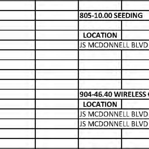
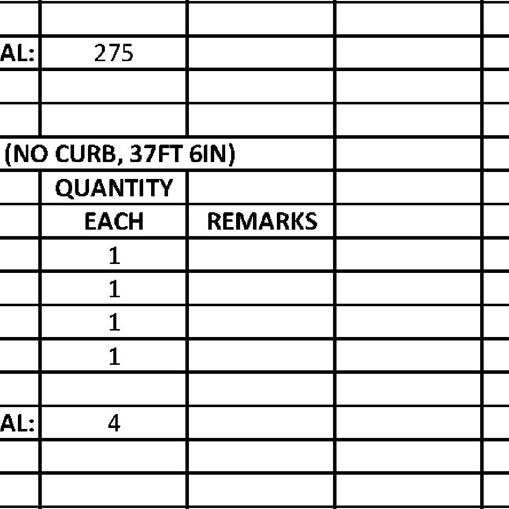
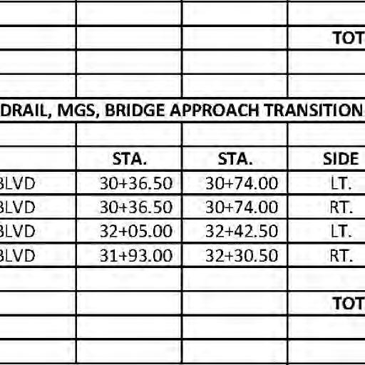
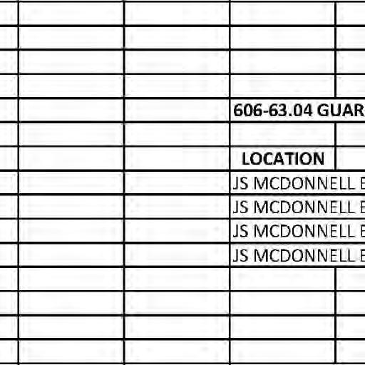
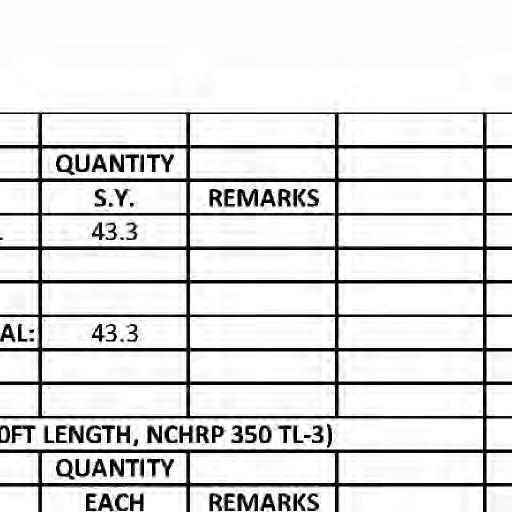
50' TYPE A CRASHWORTHY
GUARDRAIL TERMINAL
78' MGS GUARDRAIL
37.5' MGS BRIDGE TRANSITION SECTION
ANY ERROR IN THE INFORMATION.
CONTRACTOR SHALL COORDINATE THEIR ACTIVITIES IN COOPERATION WITH UTILITY COMPANIES. 2.
ALL DIMENSIONS ARE APPROXIMATE AND SHALL BE FIELD VERIFIED AND DETERMINED PRIOR TO 3.
MATERIAL PURCHASING.
ALL CONSTRUCTION AND MATERIALS SHALL BE IN ACCORDANCE WITH THE CURRENT ST. LOUIS 4.
COUNTY STANDARD SPECIFICATIONS FOR ROAD AND BRIDGE CONSTRUCTION, ST. LOUIS COUNTY
STANDARD DRAWINGS, AND MISSOURI STANDARD PLANS FOR HIGHWAY CONSTRUCTION WHEN
NOTES: AND NOTES.
NOT OTHERWISE COVERED.
EROSION CONTROL MEASURES.
DRIVEWAYS ADJUST LOCATION OF MOVEABLE BARRICADES AS NECESSARY TO MAINTAIN ACCESS TO 6.
7. AND AS DIRECTED BY THE ENGINEER.
THE COST OF ALL TEMPORARY EROSION CONTROL MESASURES SHALL BE CONSIDERED COMPLETELY
LESS THAN 1 ACRE)".
41' MGS GUARDRAIL
37.5' MGS BRIDGE TRANSITION SECTION
26 00 27 00 28 00 29 32
NOTE:
SEE DETOUR PLAN FOR ADDITIONAL
TRAFFIC CONTROL SIGNAGE, LEGEND,
BARRIER TYPE D ON BRIDGE (SEE BRIDGE PLANS)
37.5' MGS BRIDGE TRANSITION SECTION
128' MGS GUARDRAIL
50' TYPE A CRASHWORTHY GUARDRAIL TERMINAL
3
BOULEVARD R11-2
J S MCDONNELL
00
36 00
50' TYPE A CRASHWORTHY GUARDRAIL TERMINAL
28' MGS GUARDRAIL
37.5' MGS BRIDGE TRANSITION SECTION
BARRIER TYPE D ON BRIDGE (SEE BRIDGE PLANS)
CURB INLET CHECK SCALE: 1" = 50'
50 100 150
by R E SP ON S I B I L I T Y S C A
h i h
ny li it d
nd a u t ho r i ze d by m y s ea l a r e do c u m e n t s i n t e nd e d t o b e I h DESIGNED:
by d i l i
ll t h h
i f i ti pon i b ility f
i
b E s ti m a t e s R e po r t s o r o t h e r D
i f t h t t h O P U B L I C W O R K S T R AN SP O R T A T I ON
BR I DG E NO 164 J S M C DONN ELL B L VD
S
20MSD-00355 N 0 SCALE IN FEET
i
nd d
f h l ting
j t d f
i
ny p
NO E2009027953 C E R T I F I C A TE O F AU T HO R I T Y S T L OU I S M O 63101 911 W A S H I NG T ON AV E S TE 620
STP-4900(640) 6905C-20 10K, 10L 01/06/2023 L I C E N S E NO 023795 P R O F E SS I ONA L E NG I N EE R M A RC W E S H EL M AN M.W.E. M.R.B. M.S.M. OF 63
12
F E A T U R E S AND T R A FF I C S A F ET Y E R O S I ON C ON T R O L
FEDERAL PROJECT NO. AR-1518 SHEET SEQUENCE: COUNTY PROJECT NO. E-W GATEWAY TIP NO. R E V I S I ON S R E V DA TE B Y A PP D E S CR I P T I ON MSD BASE MAP: MSD: DRAWN: DATE: CHECKED: i
50' TYPE A CRASHWORTHY GUARDRAIL TERMINAL
COVERED BY THE LUMP SUM CONTRACT UNIT PRICE FOR "EROSION CONTROL MEASURES (SITES
REFER TO MODOT STANDARD PLAN 806.10J FOR DETAILS OF CONSTRUCTION OF TEMPORARY 5.
Notes:
All bents are parallel.

All dimensions are horizontal.
The locations of all subsurface borings for this structure are shown on
is given to the subsurface data available from the County or elsewhere. weight should be given to the boring data depicted on the plan sheets than the Project Contact upon written request. No greater significance or in the Electronic Bridge Deliverables. They will also be available from of the project, are shown on Bridge Sheets No. 40-43 and may be included subsurface data and investigations performed by the County for the design indicated, as well as any other boring logs or other factual records of the plan sheet for this structure. The boring data for all locations
The County does not represent or warrant that any such boring data
Notice and Disclaimer Regarding Boring Log Data expressly warranted, which the contractor may obtain from the County. or those available from the County, or on any other documentation not prices, time, or schedule of performance on the boring data depicted here project. A contractor assumes all risks it may encounter in basing its bid accurately dipicts the conditions to be encountered in constructing this
contract unit price for roadway excavation. fill will be considered completely covered by the shall be removed as shown. Removal of existing roadway Existing roadway fill under the ends of the bridge
falling within the embankment section. the end bents before any piles are driven for any bents for not less than 25 feet in back of the fill face of concrete beam within the limits of the structure and section and up to the elevation of the bottom of the Roadway fill shall be completed to the final roadway
For General Notes, Foundation Data Table, and Estimated
Quantities, see Bridge Sheet No. 2.
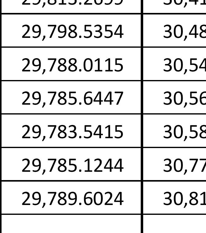
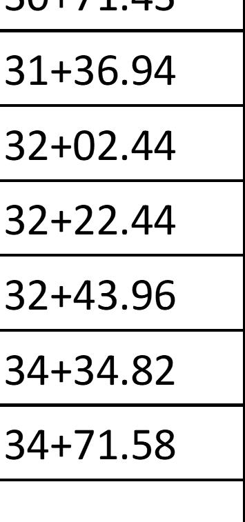
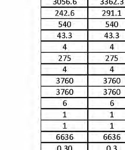
H-Piles Ë Steel H-Piles Ë Steel 2" STEEL CONDUIT ATTACHED TO BRIDGE PULL BOX PULL BOX 42 " RCP 4" HDPE PRESSURE SEWER ATTACHED TO BRIDGE (FUSRAP) THIS DRAWING IS NOT TO SCALE, FOLLOW DIMENSIONS ELEVATION PLAN & GENERAL FEDERAL PROJECT NO. SHEET SEQUENCE: COUNTY PROJECT NO. E-W GATEWAY TIP NO. REVISIONS REV. DATE BY APP. DESCRIPTION MSD BASE MAP: MSD: DRAWN: DATE: CHECKED: engineering project or survey used for any part of the relating to or intended to be documents or instruments Estimates, Reports or other Drawings, Specifications, responsibility for all other hereby disclaim any limited to this sheet, and I authorized by my seal are documents intended to be I hereby specify that the DESIGNED: RESPONSIBILITY ST. LOUIS COUNTY BRIDGE NO. MODOT BRIDGE NO. BRIDGE SHEET NO. PUBLIC WORKS TRANSPORTATION 096B164 164 J.J.G. R.S.N. J.J.G. 01/06/2023 MO PE NO. E-23263 PROFESSIONAL ENGINEER JOHN J. GRUENDLER NO. E-2006035000 CERTIFICATE OF AUTHORITY ST. LOUIS, MO 63126 11414 GRAVOIS RD, SUITE 201 20MSD-00355 13 OF 63 PLAN (64' - 64') PRESTRESSED CONCRETE NU-GIRDER SPANS " " Indicates location of borings. at End of Slab @ Ë Roadway Profile Grade Elev. 528.02 Sta. 30+71.43 at End of Slab @ Ë Roadway Profile Grade Elev. 528.17 Sta. 32+02.44 P.G. Elev. 528.02 Sta. 30+70.93 Fill Face End Bent No. 1 P.G. Elev. 528.17 Sta. 32+02.95 Fill Face End Bent No. 3 P.G. Elev. 528.24 Sta. 31+36.94 Flow Ë Rock Socket Shaft and Ë Drilled Ë Column, Ë Pile Ë Pile 3'-0" 21" 15" 15" 21" 3'-0" Bent No. 2 Ë Intermediate Special Provisions) Specifications and per Std. (To be removed Existing Bridge (Typ.) 2'-0" 2:1 (Normal) Fix. Fix. 2:1 (Normal) Wall Elev. 506.44 Bottom of Web Casing, and Shaft, Permanent Top of Drilled 2 12" (Typ.) (Roadway Item) Transition (Typ.) MGS Bridge Approach 1 3 Ë Structure S hou l d e 30 120 " 12 '0 120 12 '0 D i m e n s i n s R a d i a l H o r i z on t a l S hou l d e r S h a r e d U s e 50 588 " O u tt oou t AR-1518 6905C-20 STP-4900(640) L a n e L a e L a n e L a n Line Profile Grade Ë Roadway & ( T yp e D ) B a rr i e r 16 ( T yp e D ) B a rr i e 1 6 GENERAL ELEVATION (Survey Date 2019) Ground Line 64'-3„ 64'-2ƒ Span (1-2) Span (2-3) 1'-9 " 132'-0‚" Along Ë Roadway Arc Dimensions -1 12% +2 00% 480' V.C. 5°00'00" this line parallel to All bents are R a d i a l 10 End Bent No. 1 Fill Face Fill Face End Bent No. 3 1 OF 43 10K, 10L B-2 B-1 B-3 BRIDGE NO. 164 J.S. MCDONNELL BLVD. Item) (Typ.) wall) (Roadway perimeter toe 2'x2.5' deep Fabric (Includes Control Geotextile Permanent Erosion Blanket with 2'-0" Type 2 Rock 30+93.00 Sta. Line at Radial 9 Spa @ 62 " = 55 '6 " 9 Spa @ 6 '3 = 563 Exist. 42" RCP (Type D) Barrier 529.97 Elev. 30+87.32 VPI 1'-9 " 15 '1 15 '1 151 " 76½ 7 '6½ " Ë Bent 12 " (Min.) 4'-0" 32 " 3 '0 " 15 " Ë Bent 3 '1⅛ " 3 '0⅞ " Ë Bent 10¾
in Place) shoring (Use sheet pile Existing Elev. 523.97 Design Flood Elev. 443.40 Competent Rock Anticipated Top of Elev. 431.40 of Rock Socket Anticipated Bottom 1/3/2023 12:53:30 PM
Class B Concrete (Substructure)
Class B-2 Concrete (Superstructure on
Concrete "NU" Girder)
f'c = 3,000 psi
f'c = 4,000 psi
f'c = 4,000 psi
Reinforcing Steel (Grade 60) fy = 60,000 psi
For prestressed girder stresses, see Bridge Sheets No. 18 - 21.
Neoprene Pads:
Laminated Neoprene Bearing Pads shall be 60 durometer and shall be in accordance
with Sec 716.
Joint Filler:
All joint filler shall be in accordance with Sec 1057 for preformed sponge
rubber expansion and partition joint filler, except as noted.
Reinforcing Steel:
Minimum clearance to reinforcing steel shall be 1-1/2" unless otherwise noted.
mechanical bar splices and they will be considered completely covered by the in accordance with Sec 706 or 710 except that no measurement will be made for MBS refers to mechanical bar splices. Mechanical bar splices, if used, shall be
for other items.
contract unit price
Sets of bars shown on the plans shall be "equally spaced" unless specifically
noted otherwise.
Concrete:
All exposed edges of concrete shall have a 3/4" chamfer unless noted otherwise.
The special provision for Internally Cured Concrete (ICC) shall apply to the
bridge deck, concrete approach pavement, bridge approach slabs, and barrier
(See Special Provisions).
Miscellaneous:
High strength bolts, nuts, and washers will be sampled for quality assurance as
specified in Sec. 106.
"Sec" refers to the sections in the standard and supplemental specifications unless
specified otherwise.
Traffic Handling:
Structure to be closed during construction. Traffic to be maintained on other routes
during construction.
Roadway Striping:
Final striping to be completed by St. Louis County forces.
Bridge Location:
Township = 46N
Range = 6E
Section = 5
Bridge Number:
MoDOT Bridge No. 096B1641
Estimated Quantities for Class "B-2" Concrete
(Superstructure on Concrete "NU" Girder)
"B-2" Concrete
All piles shall be galvanized down to the minimum galvanized penetration (elevation).
Pile point reinforcement need not be galvanized. Shop drawings will not be required
for pile point reinforcement.
HP piles are anticipated to be driven to refusal on rock. Review all borings for depth
of rock and restrict driving as appropriate to comply with hard rock driving criteria
(See Special Provisions).
The table of Estimated Quantities for Class "B-2" Concrete (Superstructure on Concrete
contract unit price. in the estimated quantities but the variations cannot be used for an adjustment in the completely covered by the contract unit price for the slab. Variations may be encountered for conventional forms, all concrete and epoxy coated reinforcing steel will be considered of bridge slab (or with the horizontal dimensions as shown on the plan of slab). Payment square yard longitudinally from end of slab to end of slab and transversely from out to out estimate for concrete slabs. The area of the concrete slab will be measured to the nearest "NU" Girder) represents the quantities used by the Department in preparing the cost
Method of forming the slab shall be as shown on the plans and in accordance with Sec 703.
All hardware for forming the slab to be left in place as a permanent part of the structure
shall be coated in accordance with ASTM A123 or ASTM B633 with a thickness class SC 4 and a
finish type I, II or III.
Slab shall be cast-in-place with conventional forming. Precast
prestressed panels will not be permitted.
Class "B-2" Concrete (Superstructure on Concrete "NU" Girder)
Laminated Neoprene Bearing Pads (P/S Structures)
Prestressed Concrete Members, NU-Girders
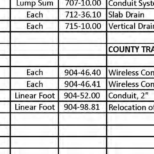
Drain
All concrete above the construction joint in the end bents is included in the Estimated
Quantities for Class "B-2" Concrete (Superstructure on Concrete "NU" Girder).
All reinforcement in the end bents is included in the Estimated Quantities for Class "B-2"

Concrete (Superstructure on Concrete "NU" Girder).
All reinforcement in the intermediate bent concrete diaphragms except reinforcement embedded
(Superstructure on Concrete "NU" Girder). in the beam cap is included in the Estimated Quantities for Class "B-2" Concrete
for
THIS DRAWING IS NOT TO SCALE, FOLLOW DIMENSIONS Design Unit Stresses: Standard Specifications: * Class 1 Excavation Superstr. Total Item Estimated Bridge Quantities ** Non-Federal
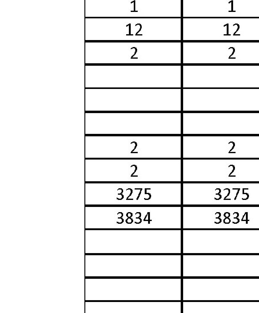
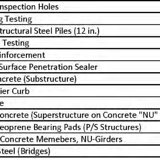
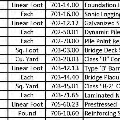
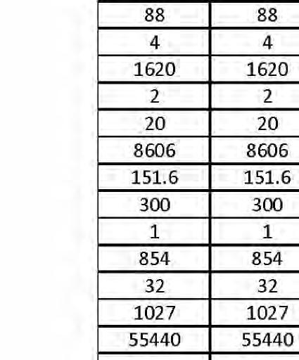
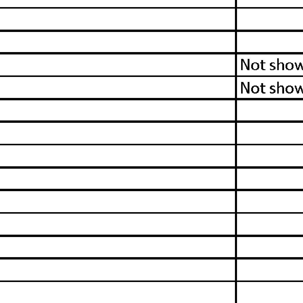
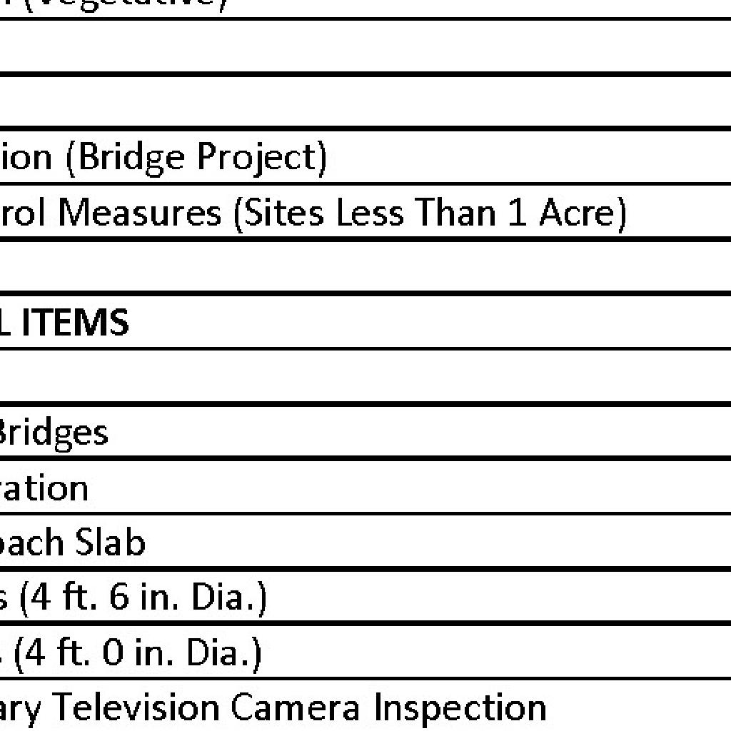
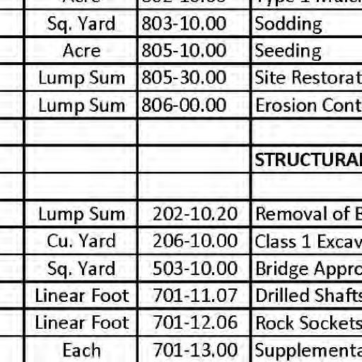
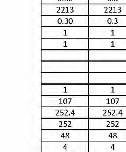
Item cu. yard Removal of Bridges Pile Point Reinforcment cu. yard cu. yard lump sum linear foot linear foot each sq. yard Bridge Approach Slab sq. yard Bridge Deck Surface Penetration Sealer Bridge Plaque each sq. ft. Class "B" Concrete (Substructure) Item No. 202-10.20 206-10.00 503-10.00 702-12.12 702-70.00 703-03.00 703-20.03 703-42.13 703-45.01 703-44.40 705-60.23 Total Class B-1 Concrete (Barrier) HYDROLOGIC DATA Estimated Backwater = 0.62 ft. Average Velocity thru Opening = 5.8 ft/s Overtopping Flood Elevation = 524.64 Edition, where specifically stated. Missouri Standard Specifications for Highway Construction, 2022 - Third Saint Louis County Standard Specifications for Road and Bridge Construction pound Reinforcing Steel (Epoxy Coated) Galvanized Structural Steel Piles (12 in.) linear foot Dynamic Pile Testing each 702-50.01 703-71.65 each each 712-36.10 each Vertical Drain at End Bents 715-10.00 Slab
participating item * Type D barrier shall be cast-in-place.
Substr.
QUANTITIES GENERAL NOTES &
Class
Structural Steel HP Pile (ASTM A709 Grade 50S) fy = 50,000 psi 297.8 81,300 Type 'D' Barrier Curb Drainage Area = 8.30 sq. miles Overtopping Flood Discharge = 13,110 cfs Roadway Overtopping - - 1 107.0 - 107.0 - 252.4 1620 - 1620 2 - 2 20 - 20 - 8606 151.6 - 151.6 - 300 300 - - 1 - 854 854 - 32 32 1027 1027 - 12 12 - - 2 FEDERAL PROJECT NO. SHEET SEQUENCE: COUNTY PROJECT NO. E-W GATEWAY TIP NO. REVISIONS REV. DATE BY APP. DESCRIPTION MSD BASE MAP: MSD: DRAWN: DATE: CHECKED: engineering project or survey used for any part of the relating to or intended to be documents or instruments Estimates, Reports or other Drawings, Specifications, responsibility for all other hereby disclaim any limited to this sheet, and I authorized by my seal are documents intended to be I hereby specify that the DESIGNED: RESPONSIBILITY ST. LOUIS COUNTY BRIDGE NO. MODOT BRIDGE NO. BRIDGE SHEET NO. PUBLIC WORKS TRANSPORTATION 096B164 164 J.J.G. R.S.N. J.J.G. 01/06/2023 AR-1518 6905C-20 MO PE NO. E-23263 PROFESSIONAL ENGINEER JOHN J. GRUENDLER NO. E-2006035000 CERTIFICATE OF AUTHORITY ST. LOUIS, MO 63126 11414 GRAVOIS RD, SUITE 201 20MSD-00355 14 OF 63 STP-4900(640) Pile Type and Size Number kip Foundation Data 1 2 Pile Driving Verification Method Type Bent No. Design Data ft. ea. ea. Pile Point Reinforcement ft. Approximate Length Per Each 3Foundation Material Number ft. Socket Rock Elevation Range ksf(Side Resistance) Compressive Resistance Minimum Nominal Axial Pile Bearing Load Min. Galvanized Penetration (Elev.) Compressive Resistance Minimum Nominal Axial Resistance Factor Continuous Composite for live load. Superstructure: Simply-Supported, Non-Composite for dead load. Earth = 120 lb/cf, Equivalent Fluid Pressure 45 lb/cf (Min.) Future Wearing Surface = 35 lb/sf Vehicular = HL-93 Design Loading: Seismic Design Category = B 2014 Interim Revisions (Seismic Details) 2011 AASHTO Guide Specifications for LRFD Seismic Bridge Design (2nd Ed.) and 2017 - AASHTO LRFD Bridge Design Specifications, 8th Edition Design Specifications: GENERAL NOTES: completely covered by the contract unit price for other items. The cost of any required excavation to the top of the drilled shafts will be considered price for Galvanized Structural Steel Piles (12 in.) Type 1 bolts, complete in place, will be considered completely covered by the contract unit Cost of L4x4 ASTM A709 Grade 36 HP pile anchors and 3/4-inch diameter ASTM F3125 Grade A325 Class "B-2" Concrete (Superstructure on Concrete "NU" Girder). All concrete above the intermediate beam cap is included in the Estimated Quantities
HP12x53 499 10 80 All 264-HP12x53 499 10 82 All 264----4 Rock 440-424 32 2 OF 43 10K, 10L
Min. Top of Deck Elev. = 526.34 Low Bottom of Girder Elev. = 522.59 50 Year Storm Elev. = 522.83 15 Year Storm Elev. = 520.41 Note: BRIDGE NO. 164 J.S. MCDONNELL BLVD. Overtopping Flood Frequency = 500 years DT DT 0.65 0.65 Design Flood Elevation = 523.97 Design Flood Discharge = 9,750 cfs Design Flood Frequency = 100 years Freeboard (50-year) Freeboard = 0 ft
Resistance Factor Maximum Factored Loads Minimum Nominal Axial Compressive Resistance = Loading Bearing Pile: Resistance Factors Maximum Factored Loads Minimum Nominal Axial Compressive Resistance (Side Resistance) = Rock Socket (Drilled Shafts): DT = Dynamic Testing ea. ** Drilled Shafts (4 ft, 6 in. Dia.) 701-11.07 252 - 252 linear foot Rock Sockets (4 ft. 0 in. Dia.) linear foot 48.0 - 48.0 701-12.06 Supplementary Television Camera Inspection each 4 - 4 701-13.00 Foundation Inspection Holes linear foot 88.0 - 88.0 701-14.00 Sonic Logging Testing each 4 - 4 701-16.00 Reinforcing Steel (Bridges) pound 55,440 - 55,440 706-10.60 Conduit System on Structure lump sum - - 1 707-10.00 252.4 86061/3/2023 12:54:35 PM

31 + 00 32 + 00 FEDERAL PROJECT NO. SHEET SEQUENCE: COUNTY PROJECT NO. E-W GATEWAY TIP NO. REVISIONS REV. DATE BY APP. DESCRIPTION MSD BASE MAP: MSD: DRAWN: DATE: CHECKED: engineering project or survey used for any part of the relating to or intended to be documents or instruments Estimates, Reports or other Drawings, Specifications, responsibility for all other hereby disclaim any limited to this sheet, and I authorized by my seal are documents intended to be I hereby specify that the DESIGNED: RESPONSIBILITY ST. LOUIS COUNTY BRIDGE NO. MODOT BRIDGE NO. BRIDGE SHEET NO. THIS DRAWING IS NOT TO SCALE, FOLLOW DIMENSIONS PUBLIC WORKS TRANSPORTATION 096B164 164 J.J.G. R.S.N. J.J.G. 01/06/2023 MO PE NO. E-23263 PROFESSIONAL ENGINEER JOHN J. GRUENDLER NO. E-2006035000 CERTIFICATE OF AUTHORITY ST. LOUIS, MO 63126 11414 GRAVOIS RD, SUITE 201 20MSD-00355 15 OF 63 AR-1518 6905C-20 STP-4900(640) PLAN SUBSTRUCTURE LAYOUT Span (2-3) 65'-3" Span (1-2) 65'-9‡" Sta. 30+70.93 Radial Line @ Sta. 31+36.94 Radial Line @ Sta. 32+02.95 Radial Line @ Sta. 30+93.00 Radial Line @ End Bent No. 1 Fill Face Bents @ Ë Roadway Line Parallel to 03°44'08" 05°00'00" 90°00'00"84°22'25" 95°37'35" 01 53 '28 " Chord A 2'-2⅛" 95°37'35" 80°35'29" 07°31'03" No. 2 Ë Int. Bent Chord B Extension Chord A 03° 46' 56" Bent No. 3 Fill Face End Ë Roadway 80°35'29" 99°24'31" 8'-8�" End Bent No. 1 at Fill Face of to Ë Roadway Line Tangent All dimensions are horizontal. All bents are parallel. General Notes: along Tangent Horizontal Dimensions along Ë Roadway Horizontal Arc Dimensions 66'-0„ 132'-0‚" 3 OF 43 10K, 10L Bent No. 1 Ë End Bent No. 2 Ë Int. No. 3 Ë End Bent 11°17'59" (Chord Length) 66'-0" (Chord Length) 66'-0" Detail A Detail B Detail C 1 0ƒ Ë Roadway Ë End Bent No. 1 No. 1 End Bent Fill Face DETAIL A Ë Roadway DETAIL B Bent No. 2 Ë Int. Ë Roadway No. 3 End Bent Fill Face DETAIL C Bent No. 3 Ë End 66'-0„" BRIDGE NO. 164 J.S. MCDONNELL BLVD. 90° 90° Center of Bent Geometric 1 2 " 90° 1 5 Œ Ë Structure R ad i a l 12 1/3/2023 12:58:01 PM
The U bars and pairs of V bars shall be placed
parallel to Ë of roadway.
Reinforcing steel shall be shifted to clear
piles. U-bars shall clear piles by at least 1½".
Reinforcement in wingwall plan of beam not shown
for clarity.
For details of End Bent No. 1 not shown, see
Bridge Sheets No. 5-7.
8 7 6 5 4 3 2 1 7'-6" 7'-6" 7'-6" 7'-6" 7'-6" 7'-6" 7'-6" Varies Varies End Bent No.1 Fill Face of 16" 16" 93°47'33" & Ë Key Ë Bent 18" 18" 3'-0" 3" 15" 21" 2-#6-H102 Bent No. 1 Fill Face of End PLAN OF BEAM SHOWING REINFORCEMENT PLAN OF BEAM Ë Girder Ë Girder Ë Girder Ë Girder 6'-2" ( T yp ) 1 " (Typ.) 3'-0⅞" (T yp ) 6 ( T y p ) 1 8 (Typ.) 18" 86°19'55" (Top & Bot.) (Typ.) Pile Anchor Ë Structure Radial 1'-0" Ë Structure Radial 1'-0" 6'-2" 6'-2" 6'-2" 6'-2" 6'-2" 6'-2" 6'-2" 19¾" Ë Pile Ë Pile Ë Pile Ë Pile Ë Pile 9" 5'-0" 2'-6½" 2'-6½" 5'-0" 19⅞" 3'-1⅛" 10" 4" 29'-4�" 29'-4�" 10ƒ" Ë Bent 5'-0" 12" 6'-0" 2'-0" 12" 5'-0" 5'-0" 5'-0" 12" 6'-0" 2'-0" 12" 5'-0" 5'-0" @ 12" 2 spa. @ 12" 3 spa. @ 12" 2 spa. 24-#5-U101 ( ) 52-#4-U102 ( ) 12-#4-U103 ( ) 4 Pr.-#5-V101 ( ) Ë Bent (Typ.) bearing pad thicker than the compressed is no filler that when minimum joint girder with 1½" Fill area under Sheet No. 5) detail Bridge Pad (Typ.) (See Neoprene Bearing Laminated 1¼" Thick & Ë Piles Ë Bearing 3⅞" Ë Piles (Measured along Ë Piles) Ë Girders (Measured along Ë Bearing) Measured along Ë Bent 4�" 6" Ë Bent 10¾" Note: Keys & Beam Steps not shown for clarity. See Bridge Sheet 5 for Reinforcement of Beam Steps. 6" 4�" 58'-9⅝" 2'-11¾" 7'-6�" 7'-6�" 7'-6�" 3'-10" 7'-6�" 7'-6�" 7'-6�" 3'-0�" 4'-4" 2'-6½" 2'-6½" 5'-0" 5'-0" 2'-6½" 2'-6½" 5'-0" 7'-10�" 6'-0" 31'-0" 6'-0" 7'-10�" 16�" 6" 18'-0" 6'-0" 2 Spa. @ 6" 5'-0" 2 Spa. @ 6" 6'-0" 18'-0" 6" 16�" 2'-4�" 5 Spa. @ 6" 4'-0" 7 Spa. @ 6" 4'-0" 6 Spa. @ 6" 4'-6" 3 Spa. @ 6" 2'-0" 4'-0" 2'-0" 3 Spa. @ 6" 4'-6" 6 Spa. @ 6" 4'-0" 7 Spa. @ 6" 4'-0" 5 Spa. @ 6" 2'-4�" 6"x3" (Typ.) Const. Jt. Key (Typ.) 4-#6-H101 18" 18" 3'-0" 27'-11⅝" 28'-2" 810 ⅞ " 91 Const. Joint Keys & Beam Steps (Measured along Ë Bent)
3'-0⅞" 3'-8�" 15�" 5'-0" 4'-5¼" 15�" Profile Grade Ë Roadway & Profile Grade Ë Roadway & THIS DRAWING IS NOT TO SCALE, FOLLOW DIMENSIONS Notes: PLANS END BENT 1 FEDERAL PROJECT NO. SHEET SEQUENCE: COUNTY PROJECT NO. E-W GATEWAY TIP NO. REVISIONS REV. DATE BY APP. DESCRIPTION MSD BASE MAP: MSD: DRAWN: DATE: CHECKED: engineering project or survey used for any part of the relating to or intended to be documents or instruments Estimates, Reports or other Drawings, Specifications, responsibility for all other hereby disclaim any limited to this sheet, and I authorized by my seal are documents intended to be hereby specify that the DESIGNED: RESPONSIBILITY DISCLAIMER OF PUBLIC WORKS TRANSPORTATION J.J.G. R.S.N. J.J.G. 01/06/2023 AR-1518 6905C-20 MO PE NO. E-23263 PROFESSIONAL ENGINEER JOHN J. GRUENDLER NO. E-2006035000 CERTIFICATE OF AUTHORITY ST. LOUIS, MO 63126 11414 GRAVOIS RD, SUITE 201 20MSD-00355 16 OF 63 STP-4900(640) 10K, 10L BRIDGE NO. 164 J.S. MCDONNELL BLVD. ST. LOUIS COUNTY BRIDGE NO. MODOT BRIDGE NO. BRIDGE SHEET NO. 096B164 164 4 OF 43
84°22'25"
1/3/2023 1:07:42 PM
STEPS
FRONT ELEVATION SIDE ELEVATION 4" Ë L4x4 Ë Pile and L4x4x⅜"x10" (Typ.) Detail A 2½" 1½" 4" 4" L4x4x⅜" ⅛" 45° DETAIL A DETAILS OF HP PILE ANCHORS STEEL PILE SPLICE nut each. two washers and one ¾"Ó H.S. bolts with Ë Two �"Ó Holes for (If required) * Galvanizing material shall be omitted or removed 1 inch clear of weld locations. See special provisions. to be cut square) of lower section Butt splice. (Top * End Bent No.1 Fill Face of & Ë Key Ë Bent 18" 18" 3'-0" Ë Structure Radial 1'-0" Ë Pile Ë Pile Ë Pile Ë Pile Ë Pile 5'-0" 5'-0" Ë Bent 5'-0" 5'-0" 5'-0" 6"x3" (Typ.) Const. Jt. Key 8 7 6 5 4 3 2 1 7'-6" 7'-6" 7'-6" 7'-6" 7'-6" 7'-6" 7'-6" Varies Varies Ë Girder Ë Girder Ë Girder Ë Girder 5'-6…" 5'-6"
OF BEAM SHOWING REINFORCEMENT IN
4-#6-H105 (Top) 6" 6" @ 6" cts. 10-#4-U104 ( ) 6" 6" U.N.O.) @ 6" cts. (Typ. 9-#4-U104 ( ) 4-#6-H108 (Top)(Typ. U.N.O.) 4-#6-H106 (Top) 6" 6…" 10-#4-U104 ( ) @ 6" cts. 5'-0" Profile Grade Ë Roadway & (Typ.) „" ‚" 6" ‚" 1¼" LAMINATED NEOPRENE BEARING PAD TYPICAL SECTION THRU 6"x3'-0⅞"x1¼" Steel Shim Plate 5¾"x3'-0⅝"x⅛" seat in accordance with Sec 716. shall be bonded to the bearing Bearing pads and joint filler integral unit. and molded together to form an placed between layers of elastomer Required shim plates shall be Notes: THIS DRAWING IS NOT TO SCALE, FOLLOW DIMENSIONS THRU KEY TYPICAL SECTION 6" 3" 3" 3" Ë Key & Ë Bent Notes: FEDERAL PROJECT NO. SHEET SEQUENCE: COUNTY PROJECT NO. E-W GATEWAY TIP NO. REVISIONS REV. DATE BY APP. DESCRIPTION MSD BASE MAP: MSD: DRAWN: DATE: CHECKED: engineering project or survey used for any part of the relating to or intended to be documents or instruments Estimates, Reports or other Drawings, Specifications, responsibility for all other hereby disclaim any limited to this sheet, and I authorized by my seal are documents intended to be hereby specify that the DESIGNED: RESPONSIBILITY DISCLAIMER OF PUBLIC WORKS TRANSPORTATION J.J.G. R.S.N. J.J.G. 01/06/2023 AR-1518 6905C-20 MO PE NO. E-23263 PROFESSIONAL ENGINEER JOHN J. GRUENDLER NO. E-2006035000 CERTIFICATE OF AUTHORITY ST. LOUIS, MO 63126 11414 GRAVOIS RD, SUITE 201 20MSD-00355 17 OF 63 STP-4900(640) 10K, 10L BRIDGE NO. 164 J.S. MCDONNELL BLVD. ST. LOUIS COUNTY BRIDGE NO. MODOT BRIDGE NO. BRIDGE SHEET NO. 096B164 164 5 OF 43 see Bridge Sheets No. 4, 6, & 7. For details of End Bent No. 1 not shown, shown for clarity. Reinforcement in wingwall plan of beam not parallel to Ë Roadway. All U-bars in the end bent beam shall be placed PLAN & DETAILS END BENT 1 Item Quantity Class 1 Excavation cu. yard Class B Concrete (Substructure) cu. yard linear foot Pile Point Reinforcement each Galvanized Structural Steel Piles (12in.) on Bridge Sheet No. 2. the Estimated Quantities Table These quantities are included in Note: Substructure Quantity Table for Bent No. 1 53.0 24.2 10 800 1 Dynamic Pile Testing each 1/3/2023 1:09:29 PM
PLAN
Notes:
The #6-F101 and #6-F103 bars shall be bent in the field to clear girders.
The U bars and pairs of V bars shall be placed parallel to Ë of roadway.
Class B-2. All concrete in the end bent above top of beam and below top of slab shall be
Strands at end of the girders shall be field bent or, if necessary, cut in field
to maintain 1 1/2-inch minimum clearance to fill face of end bent.
For location of coil tie rods, #6-H118 bars (Thru Girders) and #5-H119 (strand
tie bar), see Bridge Sheets No. 18 & 19.
For details of vertical drain at end bent, see Bridge Sheet No. 8.

For details of bridge approach slab, see Sheet No. 35.
For Sections A-A, B-B, C-C, & D-D, see Bridge Sheet No. 7.
8 7 6 5 4 3 2 1 7'-6" 7'-6" 7'-6" 7'-6" 7'-6" 7'-6" 7'-6" Varies Varies 16" 16" 18" 18" 3'-0" Ë Girder Ë Girder Ë Girder Ë Girder PART PLAN SECTION NEAR END BENT Top of Wingwall Elev. 529.78 H Bars #6 & #8 H Bars #6 & #8 Slab End of @ 9" cts. 5-#6-V102 (Typ.) 4" (Top) 4-#6-H104 4-#6-H110 Diaphragm Face of 3-#6-F102 3-#6-F104 9 " 2 " Top of Wingwall Elev. 526.28 74 ⅞ 4 '7 ⅛ c t s ( E a c h F a c e ) 9#6V 104 @ 12 9 2 77 " 45 bar 2-#6-V105 bars 2-#6-V103 9-#6-F103 9-#6-F101 Girder) (Typ.) #6-H118 (Thru tie bar) (Typ.) #5-H119 (Strand 6" of Wing Inside Face 6" 56-#5-U108 at 12" cts. (See Bridge Approach Slab Details) 6" 12"x14"x2" Const. Jt. Key End Bent No.1 Fill Face of of Wing Inside Face 75-#6-U107 @ 9" cts. 19⅞" 19⅞" (Top) 4-#6-H103 28-#5-U105 & 28-#6-U106 (Spaced with U101 & Prs. of V101) Ë Structure Radial 1'-0" (Fill Face) 4-#6-H109 4-#6-H104 Girder) (Typ.) #6-H118(Thru 4-#6-H103 Elev. 528.02 Top of slab @ End of slab Profile Grade Ë Roadway & 2-#6-H102 3'-0½" Elev. 525.61 4-#6-H101 3'-6½" Elev. 522.47 4-#6-H110 (Fill Face) 1 2 '0 4-#6-H109 (Typ.)* * 5-#6-V102 spaced @ 9" (Centered behind all girder webs) 12 '0 (Typ.) 18" Elev. 518.93 4½" 1" 4¾" 1¼" 4�" 1�" 5�" 1�" 5�" 1�" 5⅝" 2⅛" 5⅞" 2⅜" Elev. 525.16 Elev. 524.71 Elev. 524.26 Elev. 523.81 Elev. 523.36 Elev. 522.92 Rod (Typ.) ¾" Ó Coil Tie Ë Bent (Typ. Ea. End) #6-H113(Front Face) Elev. 522.57 (Looking back station) 4-#6-H106 (Typ. U.N.O.) 4-#6-H108 4-#6-H105 (Typ.) Tie Rods ¾"Ó Coil 1 2 c t s ( E a c h F a c e ) 9#6V 1 0 6 @ (Typ. Ea. End) 3-#6-H113 28'-0ƒ" 28'-0‡" 12" Girders) (Typ.) Face) (Between #6-H112 (Front Girders) (Typ.) Face) (Between #6-H111 (Front Girders)(Typ.) 1-#6-H112 (Between 3-#6-H111 & Profile Grade Ë Roadway & (Typ.) #4-U104 Construction Joint Longitudinal (Typ.) 3'-9" Min. Lap Elev. 523.97 Pile Cut-off Elev. 523.59 Pile Cut-off Elev. 523.20 Pile Cut-off Elev. 522.82 Pile Cut-off Elev. 522.44 Pile Cut-off Elev. 522.06 Pile Cut-off Elev. 521.68 Pile Cut-off Elev. 521.30 Pile Cut-off Elev. 520.91 Pile Cut-off Elev. 520.53 Pile Cut-off THIS DRAWING IS NOT TO SCALE, FOLLOW DIMENSIONS
SECTION & PLAN END BENT 1 FEDERAL PROJECT NO. SHEET SEQUENCE: COUNTY PROJECT NO. E-W GATEWAY TIP NO. REVISIONS REV. DATE BY APP. DESCRIPTION MSD BASE MAP: MSD: DRAWN: DATE: CHECKED: engineering project or survey used for any part of the relating to or intended to be documents or instruments Estimates, Reports or other Drawings, Specifications, responsibility for all other hereby disclaim any limited to this sheet, and I authorized by my seal are documents intended to be hereby specify that the DESIGNED: RESPONSIBILITY DISCLAIMER OF PUBLIC WORKS TRANSPORTATION J.J.G. R.S.N. J.J.G. 01/06/2023 AR-1518 6905C-20 MO PE NO. E-23263 PROFESSIONAL ENGINEER JOHN J. GRUENDLER NO. E-2006035000 CERTIFICATE OF AUTHORITY ST. LOUIS, MO 63126 11414 GRAVOIS RD, SUITE 201 20MSD-00355 18 OF 63 STP-4900(640) 10K, 10L BRIDGE NO. 164 J.S. MCDONNELL BLVD. ST. LOUIS COUNTY BRIDGE NO. MODOT BRIDGE NO. BRIDGE SHEET NO. 096B164 164 6 OF 43 B B E E F F A A C C D D For details of End Bent No. 1 not shown, see Bridge Sheets No. 4, 5, & 7. For Elevation E-E and F-F, see Bridge Sheet No. 7. 1/3/2023 1:10:46 PM

6" (Typ.) (Typ.) …" (Typ.) …" (Typ.) 6" (Typ.) (Min.) (Typ.) #6-U106 #5-U108 #5-U101 #5-U105 #6-U107 #5-U108 #6-U107 #6-V102 #4-U103 4-#6-H101 #5-U108 #6-U107 (Typ.) (Min.) 26" #6-V102 #4-U102 18" DETAIL A (Typ.) Detail A 3" cl. #6-U107) (Typ. for #4-U104 Bar (Typ.) Strand Tie #5-H119 15" 21" Ë Pile (Typ.) 3'-0" Bar (Typ.) Strand Tie #5-H119 4-#6-H101 4-#6-H101 (Typ.) Const Jt. 12" (Min.) 2½" (Typ.) (Typ.) End of Slab Reinforcement (Typ.) Transverse Slab 4-#6-H104 Ë Roadway Elev. 528.02 @ Top of Slab #5-V101 (Typ.) #6-U106 #5-U108 (Typ.) 6" #6-U107 #5-U105 #5-V101 Jt. Const. SECTION C-C SECTION B-B SECTION D-D SECTION A-A 4'-3‡" 3'-0ˆ" End Bent (Typ.) Fill Face of 4-#6-H101 (Top & Bottom) (Typ.) Reinforcement Slab Longitudinal End Bent (Typ.) Fill Face of (Top & Bottom) Reinforcement (Typ.) Transverse Slab (Typ.) Reinforcement Slab Longitudinal Dimensions @ Ë Roadway #6-H102 (Typ.*) bearing pad thicker than the when compressed is no with Joint Filler that Fill area under girder (Typ.) (Thru Girder) #6-H118 2½" cl. (Min.) 2'-5" (Between Girders) #6-H111 #6-H112 2'-5" 4-#6-H108 (Typ. U.N.O.) #4-U104 4-#6-H108 4-#6-H103 (Typ.) (Typ.) (Typ.) #6-H112 #6-H111 (Cont.)(Typ.) #6-H110 (Typ.) (Typ.) #6-H111 (Cont.)(Typ.) #6-H109 4-#6-H101 (Typ.) (Typ.) (Typ.) (Between Girders) #6-H112 (Typ.) Const. Jt. Const. Jt. #6-V bars of wing Inside face Const. Jt. (Typ.) 2" cl. 2" cl. 3" (Each Face) #8-H bars @ 3" cts. 2" 9" Elev. 522.57 3 spa. @ 3" 2" 2" 2" 3" (Min.) 2" 2" 2" 9" 2" @ 3" 3 spa. 3" cl. Elev. 518.93 16" 9-#6-F101 @ 8" cts. ( ) 12" cts. 3-#6-F102 @ 9-#6-F103 @ 8" cts. ( ) TYPICAL SECTION THRU WING 4'-5" 4'-7⅛" Detail A Detail A 2-#6-V105 ELEVATION F-F (Each Face) #6-H bars @ 8" cts. 2-#6-V103 ELEVATION E-E 12" cts. 3-#6-F104 @ (Adjust to clear Girder bottom flange) (Adjust to clear Girder bottom flange) 12'-0" 7'-7" #6-H120 (Each Face) 7'-2½" 4'-2" 9-#6-H120 @ 8" cts. (Each Face) 3" cl. Const. Jt. #5-K bar #6-H-bars 7'-4⅞" 12'-0" #6-H122 (Each Face) 3'-6½" 9-#6-H122 @ 8" cts. (Each Face) superelevation wing to match Slope top of @ Outside Face Elev. 529.78 @ Outside Face Elev. 526.28 9-#6-V104 @ 12" cts. (Each Face) 9-#6-V106 @ 12" cts. (Each Face) 3'-0½" 3'-9�" 5" 5" 5" 7'-4�" * Placed with grade 2-#8-H121 * 2-#8-H123 * Face Outside THIS DRAWING IS NOT TO SCALE, FOLLOW DIMENSIONS Notes: DETAILS END BENT 1 See Bridge Sheets No. 4-6 for additional notes. Sheets No. 32 & 33. For reinforcement of the barrier, see Bridge see Bridge Sheet No. 6. For locations of Sections A-A, B-B, C-C, & D-D, Bridge Sheets No. 4-6. For details of End Bent No. 1 not shown, see FEDERAL PROJECT NO. SHEET SEQUENCE: COUNTY PROJECT NO. E-W GATEWAY TIP NO. REVISIONS REV. DATE BY APP. DESCRIPTION MSD BASE MAP: MSD: DRAWN: DATE: CHECKED: engineering project or survey used for any part of the relating to or intended to be documents or instruments Estimates, Reports or other Drawings, Specifications, responsibility for all other hereby disclaim any limited to this sheet, and I authorized by my seal are documents intended to be hereby specify that the DESIGNED: RESPONSIBILITY DISCLAIMER OF PUBLIC WORKS TRANSPORTATION J.J.G. R.S.N. J.J.G. 01/06/2023 AR-1518 6905C-20 MO PE NO. E-23263 PROFESSIONAL ENGINEER JOHN J. GRUENDLER NO. E-2006035000 CERTIFICATE OF AUTHORITY ST. LOUIS, MO 63126 11414 GRAVOIS RD, SUITE 201 20MSD-00355 19 OF 63 STP-4900(640) 10K, 10L BRIDGE NO. 164 J.S. MCDONNELL BLVD. ST. LOUIS COUNTY BRIDGE NO. MODOT BRIDGE NO. BRIDGE SHEET NO. 096B164 164 7 OF 43 1/3/2023 1:11:54 PM
Note: Squared end bent shown. Skewed end bent similar.
General Notes:
All drain pipe shall be sloped 1 to 2 percent.
Drain pipe may be either 6-inch diameter corrugated metallic-coated steel pipe underdrain, 4-inch diameter corrugated polyvinyl chloride (PVC) drain pipe, or 4-inch diameter corrugated polyethylene (PE) drain pipe.
Drain pipe shall be placed at fill face of end bent and inside face of wings. The pipe shall slope to lowest grade of ground line, also missing the lower beam of end bent by a minimum of 1½ inches. Drain shall be installed to discharge downstream of new bridge whenever possible.
Perforated pipe shall be placed at fill face side and inside face of wings at the bottom of end bent and plain pipe shall be used where the vertical drain ends to the exit at ground line.
The cost for furnishing and installing the drain pipe extension including excavation, as necessary, shall be included in the contract unit price for Vertical Drain at End Bents.
Line Ground Cap with ground line Cut coupler flush Beam Lower ELEVATION OF WING PLAN OF END BENT DETAIL A PART SECTION A-A OPTIONAL TURNED DRAIN ELEVATION OF WING PART PLAN Detail A Unperforated Drain Pipe (Typ.) Coupler Drain Pipe Perforated Cap Fabric (Typ.) Geotextile Drain Pipe Perforated Cap Drain Pipe Unperforated Rodent Screen ground line to slope of Cut coupler (Min.) 6" (Min.) 6" Fabric Wrap Drain Core Vertical Fabric Wrap Fabric Geotextile Drain Pipe Perforated (Section thru wing similar)
Line Ground Elbow with ground line Cut coupler flush Drain Pipe Perforated Drain Pipe Unperforated Unperforated Drain Pipe Elbow 6(Min.) " 90° (Min.)
A A ELEVATION OF END BENT Ground Line Drain Pipe Unperforated Coupler Min. Vertical Drain Core Perforated Drain Pipe (Typ.) Core (Along wing) Vertical Drain
only when straight drain is not practical.) THIS DRAWING IS NOT TO SCALE, FOLLOW DIMENSIONS END BENTS VERTICAL DRAIN AT FEDERAL PROJECT NO. SHEET SEQUENCE: COUNTY PROJECT NO. E-W GATEWAY TIP NO. REVISIONS REV. DATE BY APP. DESCRIPTION MSD BASE MAP: MSD: DRAWN: DATE: CHECKED: engineering project or survey used for any part of the relating to or intended to be documents or instruments Estimates, Reports or other Drawings, Specifications, responsibility for all other hereby disclaim any limited to this sheet, and I authorized by my seal are documents intended to be I hereby specify that the DESIGNED: RESPONSIBILITY PUBLIC WORKS TRANSPORTATION J.J.G. R.S.N. J.J.G. 01/06/2023 MO PE NO. E-23263 PROFESSIONAL ENGINEER JOHN J. GRUENDLER NO. E-2006035000 CERTIFICATE OF AUTHORITY ST. LOUIS, MO 63126 11414 GRAVOIS RD, SUITE 201 20MSD-00355 20 OF 63 AR-1518 6905C-20 STP-4900(640) 10K, 10L BRIDGE NO. 164 J.S. MCDONNELL BLVD. ST. LOUIS COUNTY BRIDGE NO. MODOT BRIDGE NO. BRIDGE SHEET NO. 096B164 164 8 OF 43 1/3/2023 1:12:54 PM
(Use
Lapping of spiral reinforcement and splicing of *
permitted. longitudinal reinforcement in this region is not
Continue spiral bars to the bottom of **
the beam cap stirrup reinforcing bars.
Lap splices for column #10 V-bars will not be
price for "Reinforcing Steel (Bridges)." will be considered completely covered by the contract Mechanical Bar Splices, if used by the contractor, the column. The cost for furnishing and installing a minimum of 2'-0" measured along the vertical axis of adjacent #10 V-bars in the columns shall be staggered for payment. If used, Mechanical Bar Splices for of Sec 706, except that no measurement will be made use of Mechanical Bar Splices meeting the requirements contractor's option, will only be permitted with the permitted. Splicing of column #10 V-bars, at the
For Section A-A, see Bridge Sheet No. 10.
For Sections B-B thru E-E, see Bridge Sheet No. 11.
16"x2"x16" (Typ.) Const. Jt. Key 4'-6"Ó (O.D.) (Typ.) 4'-0"Ó (Typ.) Elev. 506.40 Bottom of Webwall Permanent Casing, & Shaft, Top of Top of Drilled ELEVATION (Looking Ahead Station) Beam keys and dowels not shown for clarity. 4'-11�" Elev. 525.81 4'-7�" 14'-4‡" 13'-6…" 12'-7ƒ" 11'-9„" Elev. 518.16 Elev. 519.05 Elev. 519.93 Elev. 520.81 Elev. 521.22 Elev. 517.75 (Typ.) & Ë Rock Socket Ë Drilled Shaft, Ë Column, (Typ.) Steel Casing Permanent (Typ.) Elev. 505.40 Ground Line Approximate as shown) Ë Bent (Except Symm. abt. 3-#8-H210 (Min.) 3'-10" @ 2'-0" cts (Center 5- 8"x12" Long x 2" Keys 15'-1" 7'-0" 7'-6½" #5-P201 spiral @ 3" Pitch #5-P200 spiral (Typ.) (See Drilled Shaft Details Sheet) (Typ.) 2'-0"* (Typ.) 4'-0"* (Typ.) 4'-0"* Elev. 522.67 (Typ.) 9-#10-V204 Alt. w/ 9-#10V205 (Lap #10-V204 w/ #10V202 & #10-V205 w/ #10V203) Alt. w/ 9-#10V207 (Lap #10-V206 w/ #10V202 & #10-V207 w/ #10V203) 9-#10-V206 Alt. w/ 9-#10V209 (Lap #10-V208 w/ #10V202 & #10-V209 w/ #10V203) 9-#10-V208 Alt. w/ 9-#10V211 (Lap #10-V210 w/ #10V202 & #10-V211 w/ #10V203) 9-#10-V210 16"x2"x16" (Typ.) Const. Jt. Key #5-P202 spiral @ 3" Pitch #5-P203 spiral @ 3" Pitch #5-P204 spiral @ 3" Pitch 74 Pr. - #5-U201 ( ) 36 Pr. - #5-U202 ( ) 6-#8-H200 8-#9-H201 8-#9-H201 (Typ.) 74 - #4-U203 ( ) 1½" 1⅜" 1⅜" 1�" 1¼" 1�" 1" 4⅞" 4�" 4¾" 4¾" 4¾" 4�" 4�" (Each Face) 6-#6-H202 (Typ.) @ 3" cts. 13-#5-P205 7-#6-H203 7-#6-H204 7-#6-H204 7-#6-H205 7-#6-H206 7-#6-H207 7-#6-H207 7-#6-H208 (Spa. w/ H200, H201 & H202) 8-#6-H209 (Spa. w/ H200, H201 & H202) 8-#6-H209 (Typ ) 12" Between Columns) (Typ.) (Typ.) 3'-0" (Min.) 21" (Typ.) (Typ.) 2'-4" 12" (Each Face) 21-#5-H211 @ 6" cts. 6" (Each Face) 4-#5-H212 @ 6" cts. (Each Face) 1-#5-H213 (Each Face) ( ) @ 12" cts. 11 Pr.-#5-U200 (Each Face) ( ) @ 12" cts. 11 Pr.-#5-U204 (Each Face) ( ) @ 12" cts. 11 Pr.-#5-U205 Min. Lap 5'-4" THIS DRAWING IS NOT TO SCALE, FOLLOW DIMENSIONS ELEVATION INTERMEDIATE BENT 2 A B A B D D E E C C FEDERAL PROJECT NO. SHEET SEQUENCE: COUNTY PROJECT NO. E-W GATEWAY TIP NO. REVISIONS REV. DATE BY APP. DESCRIPTION MSD BASE MAP: MSD: DRAWN: DATE: CHECKED: engineering project or survey used for any part of the relating to or intended to be documents or instruments Estimates, Reports or other Drawings, Specifications, responsibility for all other hereby disclaim any limited to this sheet, and I authorized by my seal are documents intended to be hereby specify that the DESIGNED: RESPONSIBILITY DISCLAIMER OF PUBLIC WORKS TRANSPORTATION J.J.G. R.S.N. J.J.G. 01/06/2023 MO PE NO. E-23263 PROFESSIONAL ENGINEER JOHN J. GRUENDLER NO. E-2006035000 CERTIFICATE OF AUTHORITY ST. LOUIS, MO 63126 11414 GRAVOIS RD, SUITE 201 20MSD-00355 21 OF 63 AR-1518 6905C-20 STP-4900(640) 10K, 10L BRIDGE NO. 164 J.S. MCDONNELL BLVD. ST. LOUIS COUNTY BRIDGE NO. MODOT BRIDGE NO. BRIDGE SHEET NO. 096B164 164 9 OF 43
STIRRUP BAR DETAIL OF SEISMIC reinforcing bar Vertical column Stagger adjacent bar hooks around one vertical bar) (must lap 135Ñ hooks #5-P205 1/3/2023 1:14:02 PM
2'-3" 2'-3" 4'-6" Socket Shaft, & Ë Rock Ë Key, Ë Drilled Ë Bent, Ë Column, Shaft, & Ë Rock Socket Ë Column, Ë Drilled Shaft, & Ë Rock Socket Ë Column, Ë Drilled 7'-0" 15'-1" 7'-6½" 7'-6½" 15'-1" 7'-0" 5'-6" 2'-10" 4'-8⅝" 2'-10" 4'-8⅞" 2'-10" 4'-9¼" 4 316 4 116 4'-10⅞" 2'-8" 4'-11⅜" 2'-7" 4'-11½" 2'-7" 5'-7½" 59'-3" Ë Bearing 8¼" 18¾" 2'-3" 4'-6" 2'-3" Ë Bent & Ë Key 8¼" 18¾" Ë Girder Ë Column Ë Column Ë Column Ë Column 15'-1" 15'-1" 7'-6½" 7'-6½" 12" 12" #5-P204 (Spiral) (Typ.) 3" Cl. (Typ.) 4'-0"Ó 11 Pr. - #5-U205 @ 12" cts. ( ) #5-H211 (Typ.) 2'-0" 3-#8-H210 (Bottom) & Ë Web Wall Ë Bent, Ë Column, SECTION A-A PLAN OF BEAM PLAN SHOWING REINFORCEMENT Ë Girder Ë Girder Ë Girder 7'-6" 7'-6" 7'-6" 7'-6" 7'-6" 7'-6" 7'-6" (T yp ) 6" (Typ.) 3'-0⅞" Sheet 11) detail Bridge Pad (Typ.) (See Neoprene Bearing 1¼" Thick Laminated (Typ.) joint filler girder with 1¼" Fill area under 22⅜" 4" (Typ.) Filler ½" Joint (Top of Beam) 8-#9-H201 (Bottom) 6-#8-H200 8-#6-H209 3" U-Bars (Spaced as shown in Elevation) 3" 8-#6-H209 7-#6-H203 7-#6-H205 6¾" (Typ.) 2¼" (Typ.) 1 8 7 6 5 4 3 2 1 4 3 2 5 6 7 8 3'-3�" 7'-6�" 7'-6�" 7'-6�" 7'-6�" 7'-6�" 7'-6�" 7'-6�" 3'-2⅛" 2'-11" 7'-7¼" 7'-7¼" 7'-7¼" 7'-7¼" 7'-7¼" 7'-7¼" 7'-7¼" 3'-1�" (Typ.) Key 6" x 3" (Except as shown) Ë Bent Symm. abt. 29'-7½" 29'-7½" 6-#6-H202 (Top of Step) 7-#6-H204 (Top of Step) 7-#6-H204 (Top of Step) 7-#6-H206 (Top of Step) 7-#6-H207 (Top of Step) 7-#6-H207 (Top of Step) (Top of Step) 7-#6-H208 12" Radial Profile Grade Ë Roadway & Ë Structure (Except as shown) Symm. about Ë Bent 12" (Top of Beam) 8-#9-H201 Profile Grade Ë Roadway & Ë Structure (Except as shown) Symm. about Ë Bent 12" (Typ. Span (2-3) 09°24'31" 1 Layer of 30-lb (Min.) Roofing Felt or Bituminous Pile Paint (Typ.) (Typ. Span (1-2) 05°37'35" 7'-6" 7'-6" 7'-6" 7'-6" 7'-6" 7'-6" #10-V208 (Alt. w/ #10-V209 bars) #10-V209 (Alt. w/ #10-V208 bars) #10-V207 bars) #10-V206 (Alt. w/ #10-V206 bars) #10-V207 (Alt. w/ #10-V204 (Alt. w/ #10-V205 bars) #10-V205 (Alt. w/ #10-V204 bars) #5-P203 (Spiral) #5-P202 (Spiral) #5-P201 (Spiral) 11 Pr. - #5-U204 @ 12" cts. ( ) 11 Pr. - #5-U200 @ 12" cts. ( ) 23 " 4" 7'-6" 5⅞" Ë Girder Ë Girder Ë Girder Ë Girder #10-V210 (Alt. w/ #10-V211 bars) #10-V211 (Alt. w/ #10-V210 bars) (Top of Step) " 4 37 (T yp ) 4 17 THIS DRAWING IS NOT TO SCALE, FOLLOW DIMENSIONS PLANS INTERMEDIATE BENT 2 Neoprene Bearing Pad details. Section A-A, Section Thru Key, and Laminated See Bridge Sheet No. 11 for Optional Part substitution. additional payment will be made for this column-web wall at Intermediate Bent No. 2. No in Optional Part Section A-A may be used for At the contractor's option, the details shown filler up vertical face. For steps 2" or more, use 2 1/4" X 1/2" joint Notes: FEDERAL PROJECT NO. SHEET SEQUENCE: COUNTY PROJECT NO. E-W GATEWAY TIP NO. REVISIONS REV. DATE BY APP. DESCRIPTION MSD BASE MAP: MSD: DRAWN: DATE: CHECKED: engineering project or survey used for any part of the relating to or intended to be documents or instruments Estimates, Reports or other Drawings, Specifications, responsibility for all other hereby disclaim any limited to this sheet, and I authorized by my seal are documents intended to be hereby specify that the DESIGNED: RESPONSIBILITY DISCLAIMER OF PUBLIC WORKS TRANSPORTATION J.J.G. R.S.N. J.J.G. 01/06/2023 MO PE NO. E-23263 PROFESSIONAL ENGINEER JOHN J. GRUENDLER NO. E-2006035000 CERTIFICATE OF AUTHORITY ST. LOUIS, MO 63126 11414 GRAVOIS RD, SUITE 201 20MSD-00355 22 OF 63 AR-1518 6905C-20 STP-4900(640) 10K, 10L BRIDGE NO. 164 J.S. MCDONNELL BLVD. ST. LOUIS COUNTY BRIDGE NO. MODOT BRIDGE NO. BRIDGE SHEET NO. 096B164 164 10 OF 43 1/3/2023 1:15:06 PM
4'-6" Varies (Each Face) 6-#6-H202 8-#9-H201 #5-U201 3-#8-H210 2'-0" (Each Face) 6-#6-H202 4'-6" 8" (Typ.) 3" (Each Face) 6-#6-H202 4'-0"Ó 4'-6" (O.D.) #5-U201 #5-U200 & Ë Web Wall Ë Key, Ë Bent, SECTION B-B #5-U202 & Ë Rock Socket Ë Drilled Shaft, Ë Column, Ë Key, Ë Bent, (Typ.) 15" (Typ.) @ 2'-0" cts. Key 8"x2"x12" Const. Jt. Varies #9-H201 #6-H204 4'-6" 2@7" 3 @ 6" 2@7" (Typ.) 6-#8-H200 Ë Bent 7 Eq. Spa. (Typ. Top of Beam) #4-U203 4'-6" #9-H201 (Each Face) 6-#6-H202 4'-6" #5-U201 4'-6" #9-H201 SECTION C-C SECTION D-D SECTION E-E 16"x2"x16" Const. Jt. Key #8-H210 w/ 9-#10-V207 9-#10-V206 Alt. #5-P202 spiral spaced @ 3" Pitch (Each Face) #5-H213 12" Cl. 3" 3-#8-H210 2'-0" 8" #5-U200 & Ë Web Wall Ë Key, Ë Bent, (Typ.) 15" (Typ.) @ 2'-0" cts. Key 8"x2"x12" Const. Jt. (Each Face) #5-H213 12" Cl. 3" #6-D200 2'-0" (Each Face) #5-H bars #6-D200 6" #5-H212 (Each Face) (H201 bars) 2 @ 7" (Typ. Bott.) 2 @ 7" (Typ. Bott.) (Typ.) „" ‚" 6" ‚" 1¼" LAMINATED NEOPRENE BEARING PAD TYPICAL SECTION THRU 6"x3'-0⅞"x1¼" Steel Shim Plate 5¾"x3'-0⅝"x⅛" together to form an integral unit. between layers of elastomer and molded Note: Required shim plates shall be placed 12" 10" 12" 2'-0" Ë Column & Ë Web Wall Ë Column, Ë Bent, OPTIONAL PART SECTION A-A THIS DRAWING IS NOT TO SCALE, FOLLOW DIMENSIONS Item Quantity 48.0 88.0 Substructure Quantity Table for Bent No. 2 4 4 252 SECTION THRU KEY 1" 1" 6" 15" 12" 3" #6-D200 Drilled Shafts (4 ft. 6 in. Dia.) Rock Sockets (4 ft. 0 in. Dia.) Supplementary Television Camera Inspection Foundation Inspection Holes Sonic Logging Testing Class B Concrete (Substructure) Reinforcing Steel (Bridges) linear foot linear foot each linear foot each cu. yard pound Quantities Table on Bridge Sheet No. 2. These quantities are included in the Estimated Note: 102.9 55,440 FEDERAL PROJECT NO. SHEET SEQUENCE: COUNTY PROJECT NO. E-W GATEWAY TIP NO. REVISIONS REV. DATE BY APP. DESCRIPTION MSD BASE MAP: MSD: DRAWN: DATE: CHECKED: engineering project or survey used for any part of the relating to or intended to be documents or instruments Estimates, Reports or other Drawings, Specifications, responsibility for all other hereby disclaim any limited to this sheet, and I authorized by my seal are documents intended to be hereby specify that the DESIGNED: RESPONSIBILITY DISCLAIMER OF PUBLIC WORKS TRANSPORTATION J.J.G. R.S.N. J.J.G. 01/06/2023 MO PE NO. E-23263 PROFESSIONAL ENGINEER JOHN J. GRUENDLER NO. E-2006035000 CERTIFICATE OF AUTHORITY ST. LOUIS, MO 63126 11414 GRAVOIS RD, SUITE 201 20MSD-00355 23 OF 63 AR-1518 6905C-20 STP-4900(640) 10K, 10L BRIDGE NO. 164 J.S. MCDONNELL BLVD. ST. LOUIS COUNTY BRIDGE NO. MODOT BRIDGE NO. BRIDGE SHEET NO. 096B164 164 11 OF 43 DETAILS INTERMEDIATE BENT 2 1/3/2023 1:16:20 PM
(Alt. w/ #10-V203 bars)
AR-1518 6905C-20
ANCHOR SPLICES IN SPIRAL
OUTSIDE ZONES MARKED(*))
price for "Reinforcing Steel (Bridges)." will be considered completely covered by the contract
The total bar lengths for #10 V-bars indicated in the
Mechanical Bar Splice system. be made for any adjusted bar lengths required for the minimum lap lengths shown. No additional payment will bill of reinforcing steel are determined based on the
An additional 4 feet has been added to #10-V200, #10-
cut shall be made at bottom of rock socket and 1 1/2 reinforcement lap if not required. If P200 bar is cut, bar length shall be cut off or included in the drilled shaft or rock socket depth. The additional VV201 and #5-P200 bar lengths for possible change in
turns for spiral anchorage shall be restored by field
bending.
Sonic logging testing shall be performed on all
drilled shafts and rock sockets.
Thickness of permanent casing shall be in accordance
with Sec 701.
All reinforcement in drilled shafts and rock sockets
is included in the Substructure Quantities.
The elevation of competent rock shown on the plans is
elevation shown. the competent rock elevation differs from the maintain the minimum required socket length in rock if bottom of rock socket elevation shall be adjusted to Professional Services, Ltd (September 2020). The based on the Geotechnical Report prepared by Millennia
The tip of casing shall not extend into the rock
socket elevation range reported in the Foundation Data
table without approval by the engineer.
No. 9-11. For details of Intermediate Bent 2, see Bridge sheets
164 12 OF 43 1/3/2023 1:18:27 PM
MSD BASE MAP:
DESCRIPTION
permitted. longitudinal reinforcement in this region is not Lapping of spiral reinforcement and splicing of * COUNTY PROJECT NO. E-W GATEWAY TIP NO. REVISIONS REV. DATE
BY
APP.
MSD: DRAWN:
DATE: CHECKED:
engineering project or survey used for any part of the relating to or intended to be documents or instruments Estimates, Reports or other Drawings, Specifications, responsibility for all other hereby disclaim any limited to this sheet, and I authorized by my seal are documents intended to be I hereby specify that the DESIGNED:
RESPONSIBILITY PUBLIC WORKS TRANSPORTATION J.J.G.
01/06/2023 MO PE NO. E-23263 PROFESSIONAL ENGINEER JOHN J. GRUENDLER NO. E-2006035000 CERTIFICATE OF AUTHORITY ST. LOUIS, MO 63126 11414 GRAVOIS RD, SUITE 201
J.J.G.
R.S.N.
20MSD-00355 24 OF 63
STP-4900(640) 10K, 10L BRIDGE NO. 164 J.S. MCDONNELL BLVD. ST. LOUIS COUNTY BRIDGE NO. MODOT BRIDGE NO. BRIDGE SHEET NO. 096B164
#5-P200 spiral @ 6" Pitch (Typ.) 3" 9-#10-V200 Alt. w/ 9-#10-V201 Set steel casing into sound rock in accordance with Sec 701 4'-0"* 2'-0"* Pay Limits of Rock Socket (4'-0" Diameter) 12'-0" 63'-0" Pay Limits of Drilled Shaft (4'-6" Diameter) 4'-0"Ó (Typ.) & Ë Rock Socket Ë Drilled Shaft, Ë Column, 4'-0"Ó (Typ.) Steel Casing Permanent (Typ.) Elev. 505.40 Ground Line Approximate Elev. 443.40 of Sound Rock Anticipated Top Elev. 442.40 Tip of Casing Anticipated (O.D.) 4'-6"Ó Elev. 431.40 of Rock Socket Anticipated Bottom ELEVATION OF DRILLED SHAFTS AND ROCK SOCKETS 16"x2"x16" Const. Jt. Key Elev. 506.40 Bottom of Webwall Permanent Casing, & Shaft, Top of Top of Drilled 2'-0"* #10-V-bars (See Int. Bent Sheets for Column Reinf.) 9-#10-V202 Alt. w/ 9-#10-V203 (Lap #10-V202 w/ #10-V200 & #10-V203 w/ #10-V201) ** Min. Lap 4'-1" ** Min. Lap 4'-1" ** Min. Lap 4'-1" Min. Lap 4'-1" ** 4' -0"Ó 3" Cl. Steel CasingPermanent 4'-6"Ó (O.D.) 6" Cl. of casing) (to outside (4 each shaft) logging testing for sonic 2"Ó Steel Pipe SECTION A-A SECTION B-B (Spiral) #5-P200 (Spiral) #5-P200 Top of Drilled Shaft) (Terminate Pipe at (4 each shaft) sonic logging testing 2"Ó Steel Pipe for #10-V201
#10-V200
bars) #10-V202
#10-V203
bars) THIS DRAWING IS NOT TO SCALE, FOLLOW DIMENSIONS DRILLED SHAFT DETAILS INTERMEDIATE BENT 2 A A B B TIE HOOK SEISMIC SPIRAL DETAILS OF 135Ñ
72
Lap
48
diameter
6
(Alt. w/ #10-V200 bars)
(Alt. w/ #10-V201
(Alt. w/ #10-V202
Socket V-Bars Shaft/Rock Column/Drilled Lap splice **** 48 wire diameter. or
coated bar diameter or
splice Ï
uncoated bar
****
bar diameter
SPLICES OF SPIRALS (USE FOR INTERMEDIATE AROUND VERTICAL BAR
Mechanical Bar Splices, if used by the contractor, shafts. The cost for furnishing and installing measured along the vertical axis of the drilled #10 V-bars shall be staggered a minimum of 2'-0" payment. If used, Mechanical Bar Splices for adjacent 706, except that no measurement will be made for Mechanical Bar Splices meeting the requirements of Sec contractor's option, may be done with the use of option. Alternatively, splicing of #10 V-bars, at the be ordered as full length bars, at the contractor's adjacent bars as shown. The #10-V-bar combinations may #10 V-bars lap splices shall be staggered between ** FEDERAL PROJECT NO. SHEET SEQUENCE:
PLAN OF BEAM SHOWING REINFORCEMENT PLAN OF BEAM 8 7 6 5 4 3 2 1 7'-6" 7'-6" 7'-6" 7'-6" 7'-6" 7'-6" 7'-6" Ë Girder Ë Girder Ë Girder Ë Girder 16" Varies (Typ.) 18" 79°12'25" (T yp ) 18" 3'-0" 3" 21" 15" Ë Pile Ë Pile Ë Pile Ë Pile Ë Pile 18" 18" & Ë Key Ë Bent (T yp ) 6 16" 101°48'26" Varies End Bent No.3 Fill Face of Radial 1'-0" Ë Structure Ë Structure Radial 1'-0" Ë Bent Ë Bent (Typ.) Pile Anchor Bent No. 3 Fill Face of End 4" 2'-7½" 5'-0" 12" 21⅛" 6'-3" 6'-3" 6'-3" 6'-3" 6'-3" 6'-3" 6'-3" 6'-3" 21⅝" 3'-0�" 29'-10⅞" 29'-10⅞" 24-#5-U301 ( ) 50-#4-U302 ( ) 16-#4-U303 ( ) 6 Pr.-#5-V301 ( ) 4'-6" 12" 7'-0" 2'-0" 12" 5'-0" 5'-0" 5'-0" 5'-0" 12" 2'-0" 7'-0" 12" 4'-6" 10" 5⅜" 7'-7¼" 7'-7¼" 7'-7¼" 3'-9�" 7'-7¼" 7'-7¼" 7'-7¼" Ë Bent Note: Keys and Beam Steps not shown for clarity. See Bridge Sheet 14 for Reinforcement of Beam Steps. 2'-7½" 4'-7" 5'-0" 2'-7½" 5'-0" 2'-7½" 16½" 5'-0" 5'-0" 2'-7½" 2'-7½" 4'-4½" 6" 4⅞" 6" 4⅞" @ 12" 2 Spa. @ 12" 3 Spa. @ 12" 2 Spa. 3'-3" 3'-4�" 15�" 59'-9¾" 15�" (T yp ) 1 bearing pad (Typ.) thicker than the compressed is no filler that when minimum joint girder with 1½" Fill area under Sheet No. 14) detail Bridge Pad (Typ.) (See Neoprene Bearing Laminated 1¼" Thick & Ë Piles Ë Bearing Ë Piles (Measured along Ë Piles) Ë Girders (Measured along Ë Bearing) Measured along Ë Bent 2'-10⅞" 4 Spa. @ 6" 4'-0" 8 Spa. @ 6" 4'-0" 5 Spa. @ 6" 5'-0" 3 Spa. @ 6" 2'-0" 4'-0" 2'-0" 3 Spa. @ 6" 5'-0" 5 Spa. @ 6" 4'-0" 8 Spa. @ 6" 4'-0" 4 Spa. @ 6" 2'-10⅞" 16⅞" 2 Spa. @ 6" 17'-6" 6" 6'-0" 2 Spa. @ 6" 5'-0" 2 Spa. @ 6" 6'-0" 6" 17'-6" 2 Spa. @ 6" 16⅞" 7'-4⅞" 12" 6'-0" 31'-0" 6'-0" 12" 7'-4⅞" 2-#6-H302 4-#6-H301 (Top & Bot.) 18" 18" 3'-0" 6"x3" (Typ.) Const. Jt. Key 28'-10�" 28'-3�" (Typ ) 3'-0⅞" (Typ.) Const. Joint Keys & Beam Steps (Measured along Ë Bent) 80°35'29" 8'8 9'2½" 5'-0" 13⅜" 3'-2�" 3'-9�" Profile Grade Ë Roadway & Profile Grade Ë Roadway & THIS DRAWING IS NOT TO SCALE, FOLLOW DIMENSIONS PLANS END BENT 3 FEDERAL PROJECT NO. SHEET SEQUENCE: COUNTY PROJECT NO. E-W GATEWAY TIP NO. REVISIONS REV. DATE BY APP. DESCRIPTION MSD BASE MAP: MSD: DRAWN: DATE: CHECKED: engineering project or survey used for any part of the relating to or intended to be documents or instruments Estimates, Reports or other Drawings, Specifications, responsibility for all other hereby disclaim any limited to this sheet, and I authorized by my seal are documents intended to be hereby specify that the DESIGNED: RESPONSIBILITY DISCLAIMER OF PUBLIC WORKS TRANSPORTATION J.J.G. R.S.N. J.J.G. 01/06/2023 AR-1518 6905C-20 MO PE NO. E-23263 PROFESSIONAL ENGINEER JOHN J. GRUENDLER NO. E-2006035000 CERTIFICATE OF AUTHORITY ST. LOUIS, MO 63126 11414 GRAVOIS RD, SUITE 201 20MSD-00355 25 OF 63 STP-4900(640) 10K, 10L BRIDGE NO. 164 J.S. MCDONNELL BLVD. ST. LOUIS COUNTY BRIDGE NO. MODOT BRIDGE NO. BRIDGE SHEET NO. 096B164 164 13 OF 43 Notes: Bridge Sheets No. 14-16. For details of End Bent No. 3 not shown, see for clarity. Reinforcement in wingwall plan of beam not shown ".2 1 U-bars shall clear piles by at least 1 Reinforcing steel shall be shifted to clear piles. parallel to Ë of roadway. The U bars and pairs of V bars shall be placed 1/3/2023 1:19:38 PM
PLAN OF BEAM SHOWING REINFORCEMENT IN STEPS
FRONT ELEVATION SIDE ELEVATION 4" Ë L4x4 Ë Pile and L4x4x⅜"x10" (Typ.) Detail A 2½" 1½" 4" 4" L4x4x⅜" ⅛" 45° DETAIL A DETAILS OF HP PILE ANCHORS STEEL PILE SPLICE nut each. two washers and one ¾"Ó H.S. bolts with Ë Two �"Ó Holes for (If required) * Galvanizing material shall be omitted or removed 1 inch clear of weld locations. See special provisions. to be cut square) of lower section Butt splice. (Top * 8 7 6 5 4 3 2 1 7'-6" 7'-6" 7'-6" 7'-6" 7'-6" 7'-6" 7'-6" Ë Girder Ë Girder Ë Girder Ë Girder Varies Varies Radial 1'-0" Ë Structure Ë Bent 18" 18" 3'-0" Ë Pile Ë Pile Ë Pile Ë Pile Ë Pile 5'-0" 5'-0" 5'-0" 5'-0" 5'-0" 5'-0" 5'-11" 5'-7⅞" End Bent No.3 Fill Face of 6"x3" (Typ.) Const. Jt. Key 4-#6-H305 (Top) 6" @ 6" cts. 10-#4-U304 ( ) & Ë Key Ë Bent 4-#6-H308 (Top)(Typ. U.N.O.) 6" 6" U.N.O.) @ 6" cts. (Typ. 9-#4-U304 ( ) 4-#6-H306 (Top) 6" 10-#4-U304 ( ) @ 6" cts. 5"
Profile Grade Ë Roadway & 7⅞" (Typ.) „" ‚" 6" ‚" 1¼" LAMINATED
TYPICAL SECTION
6"x3'-0⅞"x1¼" Steel Shim Plate 5¾"x3'-0⅝"x⅛"
shall
Bearing
integral unit. and
placed
Required shim plates shall be Notes: THIS DRAWING IS NOT TO SCALE, FOLLOW DIMENSIONS THRU KEY TYPICAL SECTION 6" 3" 3" 3" Ë Key & Ë Bent FEDERAL PROJECT NO. SHEET SEQUENCE: COUNTY PROJECT NO. E-W GATEWAY TIP NO. REVISIONS REV. DATE BY APP. DESCRIPTION MSD BASE MAP: MSD: DRAWN: DATE: CHECKED: engineering project or survey used for any part of the relating to or intended to be documents or instruments Estimates, Reports or other Drawings, Specifications, responsibility for all other hereby disclaim any limited to this sheet, and I authorized by my seal are documents intended to be hereby specify that the DESIGNED: RESPONSIBILITY DISCLAIMER OF PUBLIC WORKS TRANSPORTATION J.J.G. R.S.N. J.J.G. 01/06/2023 AR-1518 6905C-20 MO PE NO. E-23263 PROFESSIONAL ENGINEER JOHN J. GRUENDLER NO. E-2006035000 CERTIFICATE OF AUTHORITY ST. LOUIS, MO 63126 11414 GRAVOIS RD, SUITE 201 20MSD-00355 26 OF 63 STP-4900(640) 10K, 10L BRIDGE NO. 164 J.S. MCDONNELL BLVD. ST. LOUIS COUNTY BRIDGE NO. MODOT BRIDGE NO. BRIDGE SHEET NO. 096B164 164 14 OF 43 PLAN & DETAILS END BENT 3 Item Quantity Class 1 Excavation cu. yard Class B Concrete (Substructure) cu. yard linear foot Pile Point Reinforcement each Galvanized Structural Steel Piles (12in.) on Bridge Sheet No. 2. the Estimated Quantities Table These quantities are included in Note: Substructure Quantity Table for Bent No. 3 54.0 24.5 10 820 1 Dynamic Pile Testing each Notes: see Bridge Sheets No. 13, 15, & 16. For details of End Bent No. 3 not shown, shown for clarity. Reinforcement in wingwall plan of beam not parallel to Ë Roadway. All U-bars in the end bent beam shall be placed 1/3/2023 1:20:38 PM
NEOPRENE BEARING PAD
THRU
seat in accordance with Sec 716.
be bonded to the bearing
pads and joint filler
molded together to form an
between layers of elastomer
Notes:
The #6-F301 and #6-F303 bars shall be bent in the field to clear girders.
The U bars and pairs of V bars shall be placed parallel to Ë of roadway.
All concrete in the end bent above top of beam and below top of slab shall be
Class B-2.
Strands at end of the girders shall be field bent or, if necessary, cut in field
to maintain 1 1/2-inch minimum clearance to fill face of end bent.
For location of coil tie rods, #6-H318 bars (Thru Girders) and #5-H319 (strand
tie bar), see Bridge Sheets No. 20 & 21.
For details of vertical drain at end bent, see Bridge Sheet No. 8.
For details of bridge approach slab, see Sheet No. 35.
For Sections A-A, B-B, C-C, & D-D see Bridge Sheet No. 16.
see Bridge Sheet No. 16.
PART PLAN SECTION NEAR END BENT 3'-0" 18" 18" End Bent No.3 Fill Face of Radial 1'-0" Ë Structure 1 2 3 4 5 6 7 8 H Bars #6 & #8 9-#6-F301 2 9" 7'2 " 4'9 " bars 2-#6-V303 Top of Wingwall Elev. 529.99 @ 9" cts. 5-#6-V302 7'-6" 7'-6" 7'-6" 7'-6" 7'-6" 7'-6" 7'-6" Ë Girder Ë Girder Ë Girder Ë Girder 16" ct s (E ach Face) 9#6V306 @ 12" 78 " 43 " 9 2 16" bars 2-#6-V305 Top of Wingwall Elev. 526.42 Varies Varies 3-#6-F304 Slab End of Girder) (Typ.) #6-H318 (Thru 4-#6-H309 3-#6-F302 (Top) 4-#6-H303 Diaphragm Face of (Typ.) 4" (Typ.) Tie Rods ¾"Ó Coil (Top) 4-#6-H304 6" of Wing Inside Face 56-#5-U308 at 12" cts. (See Bridge Approach Slab Details) 6" of Wing Inside Face H Bars #6 & #8 30-#5-U305 & 30-#6-U306 (Spaced with U301 & Prs. of V301) 21½" 76-#6-U307 @ 9" cts. 21½" 6" Ë Bent tie bar) (Typ.) #5-H319 (Strand 120" 12'0 (Typ.)* 4-#6-H310 9-#6-F303 Face) (Fill 4-#6-H310 Elev. 522.61 (Typ. Ea. End) #6-H313 (Front Face) 4-#6-H303 Girder) (Typ.) #6-H318 (Thru Elev. 528.17 Top of slab @ End of slab Profile Grade Ë Roadway & 4-#6-H304 4-#6-H309 (Fill Face) 2-#6-H302 Rod (Typ.) ¾" Ó Coil Tie 4-#6-H301 18" (Typ.) 3'-6…" Elev. 522.61 Pile Cut-off Elev. 522.75 Elev. 525.77 3'-0‚" 2�" 5�" 1⅞" 5⅜" 1�" 5�" 1½" 5�" 1⅜" 4⅞" 1�" 4�" 1" 4½" Elev. 523.06 Elev. 523.51 Elev. 523.96 Elev. 524.41 Elev. 524.87 Elev. 525.32 Elev. 519.08 * 5-#6-V302 spaced @ 9" (Centered behind all girder webs) (Typ. Ea. End) 3-#6-H314 12 ct s (E ach Face) 8#6V304 @ (Looking ahead station) 4-#6-H305 4-#6-H306 (Typ. U.N.O.) 4-#6-H308 28'-6�" 28'-6�" 12¼" Girders)(Typ.) 1-#6-H312 (Between 3-#6-H311 & Girders) (Typ.) Face) (Between #6-H311 (Front Girders) (Typ.) Face) (Between #6-H312 (Front 12"x14"x2" Const. Jt. Key Profile Grade Ë Roadway & (Typ.) #4-U304 Construction Joint Longitudinal (Typ.) 3'-9" Min. Lap Elev. 520.69 Pile Cut-off Elev. 521.07 Pile Cut-off Elev. 521.46 Pile Cut-off Elev. 521.84 Pile Cut-off Elev. 522.22 Pile Cut-off Elev. 522.99 Pile Cut-off Elev. 523.38 Pile Cut-off Elev. 523.76 Pile Cut-off Elev. 524.14 Pile Cut-off THIS DRAWING IS NOT TO SCALE, FOLLOW DIMENSIONS SECTION & PLAN END BENT 3 FEDERAL PROJECT NO. SHEET SEQUENCE: COUNTY PROJECT NO. E-W GATEWAY TIP NO. REVISIONS REV. DATE BY APP. DESCRIPTION MSD BASE MAP: MSD: DRAWN: DATE: CHECKED: engineering project or survey used for any part of the relating to or intended to be documents or instruments Estimates, Reports or other Drawings, Specifications, responsibility for all other hereby disclaim any limited to this sheet, and I authorized by my seal are documents intended to be hereby specify that the DESIGNED: RESPONSIBILITY DISCLAIMER OF PUBLIC WORKS TRANSPORTATION J.J.G. R.S.N. J.J.G. 01/06/2023 AR-1518 6905C-20 MO PE NO. E-23263 PROFESSIONAL ENGINEER JOHN J. GRUENDLER NO. E-2006035000 CERTIFICATE OF AUTHORITY ST. LOUIS, MO 63126 11414 GRAVOIS RD, SUITE 201 20MSD-00355 27 OF 63 STP-4900(640) 10K, 10L BRIDGE NO. 164 J.S. MCDONNELL BLVD. ST. LOUIS COUNTY BRIDGE NO. MODOT BRIDGE NO. BRIDGE SHEET NO. 096B164 164 15 OF 43 B B E E F F C C A A D D For details of End Bent No. 3 not shown, see Bridge Sheets No. 13, 14, & 16. For Elevation E-E and F-F,
1/3/2023 1:21:49 PM
6" (Typ.) (Typ.) …" (Typ.) …" (Typ.) 6" (Typ.) (Min.) (Typ.) #6-U306 #5-U308 #5-U301 #5-U305 #6-U307 #5-U308 #6-U307 #6-V302 #4-U303 4-#6-H301 #5-U308 #6-U307 (Typ.) (Min.) 26" #6-V302 #4-U302 18" DETAIL A (Typ.) Detail A 3" cl. #6-U307) (Typ. for #4-U304 Bar (Typ.) Strand Tie #5-H319 15" 21" Ë Pile (Typ.) 3'-0" Bar (Typ.) Strand Tie #5-H319 4-#6-H301 4-#6-H301 (Typ.) Const Jt. 12" (Min.) 2½" (Typ.) (Typ.) End of Slab Reinforcement (Typ.) Transverse Slab 4-#6-H304 Ë Roadway Elev. 528.17 @ Top of Slab #5-V301 (Typ.) #6-U306 #5-U308 (Typ.) 6" #6-U307 #5-U305 #5-V301 Jt. Const. SECTION C-C SECTION B-B SECTION D-D SECTION A-A 4'-3‡" 3'-0ˆ" End Bent (Typ.) Fill Face of 4-#6-H301 (Top & Bottom) (Typ.) Reinforcement Slab Longitudinal End Bent (Typ.) Fill Face of (Top & Bottom) Reinforcement (Typ.) Transverse Slab (Typ.) Reinforcement Slab Longitudinal Dimensions @ Ë Roadway #6-H302 (Typ.*) bearing pad thicker than the when compressed is no with Joint Filler that Fill area under girder (Typ.) (Thru Girder) #6-H318 2½" cl. (Min.) 2'-5" (Between Girders) #6-H311 #6-H312 2'-5" 4-#6-H308 (Typ. U.N.O.) #4-U304 4-#6-H308 #6-H311 4-#6-H303 (Typ.) (Typ.) (Typ.) (Cont.)(Typ.) #6-H310 #6-H312 (Typ.) (Cont.)(Typ.) #6-H309 (Typ.) #6-H311 4-#6-H301 (Typ.) (Typ.) (Typ.) (Between Girders) #6-H312 (Typ.) Const. Jt. Const. Jt. #6-V bars of wing Inside face Const. Jt. (Typ.) 2" cl. 2" cl. 3" (Each Face) #8-H bars @ 3" cts. 2" 9" Elev. 519.08 3 spa. @ 3" 2" 2" 2" 3" (Min.) 2" 2" 2" 9" 2" @ 3" 3 spa. 3" cl. Elev. 522.75 16" 9-#6-F303 @ 8" cts. ( ) 12" cts. 3-#6-F304 @ 9-#6-F301 @ 8" cts. ( ) TYPICAL SECTION THRU WING 4'-3�" 4'-9�" Detail A Detail A 2-#6-V303 ELEVATION F-F (Each Face) #6-H bars @ 8" cts. 2-#6-V305 ELEVATION E-E 12" cts. 3-#6-F302 @ (Adjust to clear Girder bottom flange) (Adjust to clear Girder bottom flange) 12'-0" 7'-8�" #6-H322 (Each Face) 7'-4�" 3'-9�" 9-#6-H322 @ 8" cts. (Each Face) 3" cl. Const. Jt. #5-K bar #6-H-bars 7'-2�" 12'-0" #6-H320 (Each Face) 9-#6-H320 @ 8" cts. (Each Face) superelevation wing to match Slope top of @ Outside Face Elev. 526.42 @ Outside Face Elev. 529.99 9-#6-V306 @ 12" cts. (Each Face) 8-#6-V304 @ 12" cts. (Each Face) 3'-6⅜" 4'-2⅝" 5" 5" 5" 7'-2⅞" 3'-0¼" * Placed with grade 2-#8-H323 * 2-#8-H321 * Face Outside THIS DRAWING IS NOT TO SCALE, FOLLOW DIMENSIONS DETAILS END BENT 3 FEDERAL PROJECT NO. SHEET SEQUENCE: COUNTY PROJECT NO. E-W GATEWAY TIP NO. REVISIONS REV. DATE BY APP. DESCRIPTION MSD BASE MAP: MSD: DRAWN: DATE: CHECKED: engineering project or survey used for any part of the relating to or intended to be documents or instruments Estimates, Reports or other Drawings, Specifications, responsibility for all other hereby disclaim any limited to this sheet, and I authorized by my seal are documents intended to be hereby specify that the DESIGNED: RESPONSIBILITY DISCLAIMER OF PUBLIC WORKS TRANSPORTATION J.J.G. R.S.N. J.J.G. 01/06/2023 AR-1518 6905C-20 MO PE NO. E-23263 PROFESSIONAL ENGINEER JOHN J. GRUENDLER NO. E-2006035000 CERTIFICATE OF AUTHORITY ST. LOUIS, MO 63126 11414 GRAVOIS RD, SUITE 201 20MSD-00355 28 OF 63 STP-4900(640) 10K, 10L BRIDGE NO. 164 J.S. MCDONNELL BLVD. ST. LOUIS COUNTY BRIDGE NO. MODOT BRIDGE NO. BRIDGE SHEET NO. 096B164 164 16 OF 43 Notes: notes. See Bridge Sheets No. 13-15 for additional Sheets No. 32 & 33. For reinforcement of the barrier, see Bridge see Bridge Sheet No. 15. For locations of Sections A-A, B-B, C-C, & D-D, Bridge Sheets No. 13-15. For details of End Bent No. 3 not shown, see 1/3/2023 1:23:00 PM
21" Ë Bearing End Bent No. 1 Fill Face of 7 '6 " 7 '6 " 7 '6 " 7 '-6 " 7 '6 " 7 '6� " 7 '6� " Ë Bearing 8¼" 8¼" 7 '7¼ " 7 '-7¼ " 7 '7¼ " 7 '-7¼ " 7 '7¼ " 7 '7¼ " 7 '7¼ " End Bent No. 3 Fill Face of 7 '7¼ " 7 '7¼ " 7 '7¼ " 7 '7¼ " 7 '7¼ " 7 '7¼ " 7 '7¼ " No. 2 Ë Int. Bent Ë Bearing 21" 1 2 3 4 5 6 7 8 Ë Girder 1 2 3 4 5 6 7 8 Ë Girder 7 '6‹ " 7 '6‹ " 7 '6‹ " 7 '6‹ " 7 '-6‹ " 7 '6‹ " 7 '-6‹ " Ë Roadway Ë Structure 84°22'25" (Typ.) 80°35'29" (Typ.) 95°37'35" (Typ.) 99°24'31" (Typ.) Chord B Chord A 7 '6 7 '6 " 7 '6 " 7 '6 " 7 '6 " 7 '6 " 7 '6 " 90° 00' 00" (Typ.) Radial12 " 7 '6 " 90° 00' 00" (Typ.) 76 7 '6 " 76 7 '6 " 7 '6 7 '6 " 49 * 2 '9 " 12 "* 4 '-9¾ "* 12⅜ "* 12⅜ "* 4 '-9¾ "* 4 '-9¼ "* 2 '9 "* 2 '9 * 49 " * 12 "* 2 '-9� "* 4 '9¼ "* 2 '-9½ "* 2 '9½ "* THIS DRAWING IS NOT TO SCALE, FOLLOW DIMENSIONS FEDERAL PROJECT NO. SHEET SEQUENCE: COUNTY PROJECT NO. E-W GATEWAY TIP NO. REVISIONS REV. DATE BY APP. DESCRIPTION MSD BASE MAP: MSD: DRAWN: DATE: CHECKED: engineering project or survey used for any part of the relating to or intended to be documents or instruments Estimates, Reports or other Drawings, Specifications, responsibility for all other hereby disclaim any limited to this sheet, and I authorized by my seal are documents intended to be hereby specify that the DESIGNED: RESPONSIBILITY DISCLAIMER OF PUBLIC WORKS TRANSPORTATION J.J.G. R.S.N. J.J.G. 01/06/2023 MO PE NO. E-23263 PROFESSIONAL ENGINEER JOHN J. GRUENDLER NO. E-2006035000 CERTIFICATE OF AUTHORITY ST. LOUIS, MO 63126 11414 GRAVOIS RD, SUITE 201 20MSD-00355 29 OF 63 AR-1518 6905C-20 STP-4900(640) ST. LOUIS COUNTY BRIDGE NO. MODOT BRIDGE NO. BRIDGE SHEET NO. 096B164 164 10K, 10L BRIDGE NO. 164 J.S. MCDONNELL BLVD. LAYOUT PRESTRESSED GIRDER SPAN (1-2) PLAN * Dimension are to Chords A & B. to chords. Girders within a span are parallel All bents are parallel. All dimension are horizontal. Notes: SPAN (2-3) 17 OF 43 1/3/2023 1:25:09 PM
inner
9" strands by 1 1/2" minimum. of girders and clear reinforcing steel or 1/3 point Place vent holes at or near upgrade THIS DRAWING IS NOT TO SCALE, FOLLOW DIMENSIONS
required for ext. girders of end spans. girders. Half no. of G3, G4, and G5 not G4 and G5 not required for interior 9" (1)
steel or strands by 1 1/2" minimum. #6 bar 5~6" long and clear reinforcing Cast 1"Ó hole horizontally in girder for
(2) 1'-4" at exterior face of exterior
Detailing Reinforced Concrete Structures, the CRSI Manual of Standard Practice for Hooks and bends shall be in accordance with
Stirrup and Tie Dimensions.
Actual bar lengths are measured along
centerline of bar to the nearest inch.
Minimum clearance to reinforcing shall be 1".
All bar reinforcement shall be Grade 60.
The two D1 bars may be furnished as one bar at
the fabricator's option.
All B1 bars shall be epoxy coated.
Use 28 0.6"Ó Grade 270 strands with an initial
prestress force of 1,230 kips.
Sec 1029. Pretensioned members shall be in accordance with
Fabricator shall be responsible for location and
design of lifting devices.
coil inserts for slab drains. except for coil ties, top flange blockout and Exterior and interior girders are the same,
not drill holes in the girders. attained 75% design strength. Contractor shall and remove the bracing after the slab has girders during construction of the concrete slab for lateral and torsional stability of the The contractor shall provide bracing necessary
For Girder Camber Diagram, see Bridge Sheet
No. 25.
For location of coil inserts at slab drains, see
Bridge Sheet No. 24.
For location of coil ties and #6 bars at
concrete bent diaphragms, see Bridge Sheets
No. 6 & 22.
All dimensions are out to out. in all spans. reinforcing steel shall be used for all girders provided and may be used. The same type of
Alternate bar reinforcing steel details are
164 19 OF 43
COUNTY PROJECT NO. E-W GATEWAY TIP NO. REVISIONS REV. DATE
MSD BASE MAP:
DESCRIPTION
AR-1518 6905C-20 MO PE NO. E-23263 PROFESSIONAL ENGINEER JOHN J. GRUENDLER NO. E-2006035000 CERTIFICATE OF AUTHORITY ST. LOUIS, MO 63126 11414 GRAVOIS RD, SUITE 201
BY
APP.
MSD: DRAWN:
DATE: CHECKED:
engineering project or survey used for any part of the relating to or intended to be documents or instruments Estimates, Reports or other Drawings, Specifications, responsibility for all other hereby disclaim any limited to this sheet, and I authorized by my seal are documents intended to be hereby specify that the DESIGNED:
01/06/2023
FEDERAL PROJECT NO. SHEET SEQUENCE:
RESPONSIBILITY DISCLAIMER OF PUBLIC WORKS TRANSPORTATION J.J.G.
20MSD-00355 31 OF 63
J.J.G.
STP-4900(640) 10K, 10L BRIDGE NO. 164 J.S. MCDONNELL BLVD. ST. LOUIS COUNTY BRIDGE NO. MODOT BRIDGE NO. BRIDGE SHEET NO. 096B164
REINFORCEMENT) (ALTERNATE NU GIRDERSSPAN (1-2) 1/3/2023 1:27:27 PM
R.S.N.

A B B A WWR6 WWR5 EACH GIRDER REINFORCEMENT WELDED WIRE SHAPE 9 SHAPE 11 SHAPE 20 2 4 G5 2'-8" 20 20 2'-3" 4 G4 2 2 4 G3 3'-10" 20 9 4'-0" 4 D1 184 164 4 B1 4'-5" 11 Strands (Required) (Typ.) (2) 3/8"Ó Reinforcement Support with 3'-0" projection. Indicates cut & shop bend END VIEW SIDE VIEW PART SECTION PART ELEVATION INTERMEDIATE BENTS EXTERIOR GIRDER AT AT ALL BENTS INTERIOR GIRDER AT END BENTS EXTERIOR GIRDER TOP FLANGE BLOCKOUT & EXTERIOR GIRDER AT END BENT INTERIOR GIRDER AT ALL BENTS (Int. Bent) (End Bent) AT INTERMEDIATE BENT LEFT EXTERIOR GIRDER Rotate 180° for right ext. Reinforcement
END BENT INTERMEDIATE BENT STRANDS AT GIRDER ENDS BEARING PLATE SECTION A-A HALF ELEVATION SECTION B-B SHAPE ALTERNATE PERMISSIBLE B1 BAR COIL TIES General Notes: DIMENSIONS STRAND ARRANGEMENT VENT HOLE NO. MARK SIZE & LENGTH ACTUAL SHAPE BILL OF REINFORCING STEEL - EACH GIRDER BENDING DIAGRAMS 4'-0¼" 3'-2⅜" (Typ.) 3'-0" 3'-0‡" 8" 8" 8" 8" 18" 3" (Typ.) 12" 13" 5" 5" 4" 3" (Min.) 6" (Typ.) 6" 4" 6" (+‚",-„") 2�" 1⅜" 5½" 5�" 5⅞" Finished Smooth (Typ.) R=2" R=7⅞" (Typ.) R=7⅞" (Typ.) (Typ.) R=2" (Typ.) ¾" Chamfer 4" 2" 3 Spa. @ 2" within 1" of end of girder) (Typ.) (Cut any remaining top strands 12" projection and bend in shop Cut top 2 rows of strands with a girder end) (Typ.) strands within 1" of any remaining bottom 3'-0" projection (Cut Cut & shop bend with (Typ.) to girders) Bar (Normal #5 Strand Tie #4-D1 #4-D1 for clarity. Strands not shown Ë Bearing 4" WWR5 except as shown Symm. abt. Ë girder WWR6 #4-D1 #4-D1 WWR5 #4-B1 for clarity. Strands not shown 1¾" 16" 6" 6" 4" @ 4" cts. 5 Pr.-#4-D1 2-WWR6 and ¾" x ¾" x 18" Chamfer Blockout (Typ.) Ë Girder (½" x 5") Studs Welded Ë Two A709, Grade 36) Plate (ASTM 1/2" Bearing End of Girder (½" x 5") Studs Welded Ë Four Girder Top of Ë 3"Ó Vent Hole long (2) Tie Rods 2'-6" (Min.) Coil Ë 3/4"Ó Hole Ë 1"Ó #4-B1
(2) 2'-2" 5" 16‚" 4" 3‚" WWR5 (8" max.) 1 Spa. #4-G3 10" 1'-3Š" 1'-5Œ" #4-G4 10" #4-G5 WWR5 Face Ext. 1'-3Š" WWR5 #4-G5 Face Ext. #4-G4 10" 1'-3Š" Ë GIRDER END OF GIRDER 3'-10¼" 6" 6" 20" 6" 6" 8⅜" ƒ" 5⅛" 2" 5" W12 @ 2" D31 9 W12 (Typ.) W8 @ 6" D20 (+‚",-„") 4" (Shown looking ahead station.) 2'-11‹" 3% (Typ.) 1¾" + prestressing strand. Indicates 4ƒ" 63'-6⅝" Ë - Ë Bearing 13 Spa. @ 6" 41 Pr.-#4-B1 and 41 Pr.-#4-D1 (Spaced as shown) 11 Spa. @ 9" 14 Spa. @ 12" 6Œ" (Skew Angle) 5°37'35" Angle) (Skew 5°37'35" 23†" 3'-4†" (Skew Angle) 5°37'35" 2" 2" 2�" 2�" @ 2" 2 Spa. 4" 6" 4" @ 2" 2 Spa. @ 2" 3 Spa. @ 2" 3 Spa. 2" 2" 2�" 2�" 4" 6" 4" @ 2" 2 Spa. @ 2" 3 Spa. @ 2" 3 Spa. 2" Ë Girder Ë Girder girders at end bents.
support strands not shown for clarity. Ë Girder
about
Ë Girder. May be moved laterally in pairs.
strands to 8 kips/strand. Placed symmetrical Outer strands tensioned to 2.02 kips/strand and
A-1 with f'c = 8000 psi and f'ci = 6500 psi. Concrete for prestressed girders shall be Class breaker to this region. Fabricator shall apply a bond (1) (1)
breaker to this region. Fabricator shall apply a bond (1) (1)
about Ë Girder. May be moved laterally in pairs. inner strands to 8 kips/strand. Placed symmetrical (2) Outer strands tensioned to 2.02 kips/strand and
Strands (Required) (Typ.) (2)
2 rows of strands with a
and bend
9" (1)
9" THIS DRAWING IS NOT TO SCALE, FOLLOW DIMENSIONS
not shown 10" 10"
with 3'-0" projection. Indicates cut & shop bend prestressing strand.
Ë Girder End of Girder
Bearing
1"Ó hole horizontally in girder for #4-G4
1'-3…" (Skew Angle) 9°24'31"
#4-G5
WWR5
1'-3…"
Face Ext. spans. not required for ext. girders of end girders. Half no. of G3, G4, G5 and G6 G4 and G5 not required for interior
2 3'-10" (Skew Angle) 9°24'31"
(Skew Angle) 9°24'31"
for clarity. AT INTERMEDIATE BENT LEFT EXTERIOR GIRDER
Strands (End Bent)
not shown Rotate 180° for right ext. TOP FLANGE BLOCKOUT & EXTERIOR GIRDER AT END BENT INTERIOR GIRDER AT ALL BENTS
1'-3…"
84 D20 D20 D20 4" 8" 12" W8 W8 W8 6'-8" 8'-0" 29'-0" 6" 7" 4�" 2'-0…" Only) (WWR6 23⅝" 16¾"
Minimum clearance to reinforcing shall be 1", unless otherwise shown.
All bar reinforcement shall be Grade 60.
WWR shall not be epoxy coated.
psi and f'ci = 6500 psi.
Use 28 0.6"Ó Grade 270 strands with an initial prestress force of
1,230 kips.
long and clear reinforcing Face Ext. WWR5 #4-G5 #4-G4
or 10" WWR5
by #4-G6 #4-G3
Pretensioned members shall be in accordance with Sec 1029.
Fabricator shall be responsible for location and design of lifting
devices.
Exterior and interior girders are the same, except for coil ties,
top flange blockout and coil inserts for slab drains.
75% design strength. Contractor shall not drill holes in the concrete slab and remove the bracing after the slab has attained torsional stability of the girders during construction of the The contractor shall provide bracing necessary for lateral and
girders.
For Girder Camber Diagram, see Bridge Sheet No. 25.
No. 24. For location of coil inserts at slab drains, see Bridge Sheet
For location of coil ties and #6 bars at concrete bent diaphragms,
see Bridge Sheets No. 15 and 22.
Alternate bar reinforcing steel details are provided
164 20 OF 43
COUNTY PROJECT NO. E-W GATEWAY TIP NO. REVISIONS REV. DATE
MSD BASE MAP:
DESCRIPTION
AR-1518 6905C-20 MO PE NO. E-23263 PROFESSIONAL ENGINEER JOHN J. GRUENDLER NO. E-2006035000 CERTIFICATE OF AUTHORITY ST. LOUIS, MO 63126 11414 GRAVOIS RD, SUITE 201
BY
APP.
MSD: DRAWN:
DATE: CHECKED:
engineering project or survey used for any part of the relating to or intended to be documents or instruments Estimates, Reports or other Drawings, Specifications, responsibility for all other hereby disclaim any limited to this sheet, and I authorized by my seal are documents intended to be hereby specify that the DESIGNED:
FEDERAL PROJECT NO. SHEET SEQUENCE:
01/06/2023
RESPONSIBILITY DISCLAIMER OF PUBLIC WORKS TRANSPORTATION J.J.G.
20MSD-00355 32 OF 63
J.J.G.
STP-4900(640) 10K, 10L BRIDGE NO. 164 J.S. MCDONNELL BLVD. ST. LOUIS COUNTY BRIDGE NO. MODOT BRIDGE NO. BRIDGE SHEET NO. 096B164
NU GIRDERSSPAN (2-3) 1/3/2023 1:30:07 PM
R.S.N.
B A B A L "W"
Standard
Hooks
¾" x ¾" x 18" Chamfer Blockout (Typ.) WWR3 & WWR6 WWR1, WWR2, WWR5 WWR4 MARK SIZE WIRE S W L J 2 2 2 3 G1 4 G3 4 G4 4 G5 2'-8" 2'-3" 3'-10" 2'-10" 8 20 20 20 NO. SIZE & LENGTH ACTUAL SHAPE BILL OF REINFORCING STEEL - EACH GIRDER BENDING DIAGRAMS SHAPE 8 SHAPE 20
nearest inch. Actual bar lengths are measured along centerline of bar to the Stirrup and Tie Dimensions.
Practice for Detailing Reinforced Concrete Structures,
and bends shall be in accordance with the CRSI Manual of All dimensions are out to out.
Indicates
INTERMEDIATE BENTS EXTERIOR GIRDER AT AT ALL BENTS INTERIOR GIRDER AT END BENTS EXTERIOR GIRDER COIL TIES VENT HOLE BEARING PLATE SIDE VIEW END VIEW General Notes: WELDED WIRE PLACEMENT SECTION B-B HALF ELEVATION SECTION A-A DIMENSIONS Ë GIRDER STRAND ARRANGEMENT END OF GIRDER END BENT STRANDS AT GIRDER ENDS INTERMEDIATE BENT PART ELEVATION PART SECTION (Typ.) 12" 3" 13" 8" 18" 5" 5" 4" 3'-0‡" 8" 8" 8" long (2) Tie Rods 2'-6" (Min.) Coil Ë 3/4"Ó Hole Ë 1"Ó Ë 3"Ó Vent Hole Girder Top of (½"x5") Studs Welded Ë Four WWR6 G1 WWR4 WWR4 Cl ƒ" 5�" 5½" 1⅜" (+‚",-„") 2�" 5⅞" 2" 4" 4" 3 Spa. @ 2" 6" 3" (Min.) 6" (Typ.) ƒ" 5⅛" 5" 2" 2" d=2½" 6" 2‚" Cl ƒ" WWR J S S 2 8…" 6" 6" 20" 6" 6" 3'-10¼" 3'-3⅜" 6¾" 14„" 6⅞" 16" 16" (Typ.) 3'-0" 6" 2-WWR1 2-WWR2 2-WWR6 3'-2⅜" 4'-0¼" 1ƒ" J6 J1 J2 2-WWR3 except as shown Symm. abt. Ë Girder WWR5 Ë Bearing WWR4 WWR4 G1 WWR3 WWR5 Longitudinal Wire Wire (Typ.) Vertical @ 6" D20 (Typ.) W8 Spa. @ "S" Size Wire "W" d=2½" D11 @ 6" (Typ.) W2 girder end) (Typ.) strands within 1" of any remaining bottom 3'-0" projection (Cut Cut & shop bend with within 1" of end of girder) (Typ.) (Cut any remaining top strands 12" projection
3/8"Ó Reinforcement Support in
shop
top
Finished Smooth (Typ.) R=2" R=7⅞" (Typ.) R=7⅞" (Typ.) (Typ.) R=2" (Typ.) ¾" Chamfer (+‚",-„") 4" (Shown looking ahead station.) 2'-11‹" 3% + (Typ.) 1¾" 4ƒ" 4" for first 10 ft, then @ 12" cts.)
and 42-#3-G1 (G1 spa.
Cut
2-WWR4
with WWR4 @ 6" cts. 63'-6⅜" Ë - Ë Bearing strands by 1 1/2" minimum. of girders and clear reinforcing steel or Place vent holes at or near upgrade 1/3 point shall be used for all girders in all spans. and may be used. The same type of reinforcing steel
Plate (ASTM 1/2"
A709, Grade 36) (½"x5") Studs Welded Ë
Concrete for prestressed beams shall be Class A-1 with f'c = 8000
Two
(Typ.) to girders) Bar (Normal #5 Strand Tie
Strands
2" 2�" 2�" 2" @ 2" 2 Spa. 4" 6" 4" @ 2" 2 Spa. @ 2" 3 Spa. @ 2" 3 Spa. 2" 2" 2�" 2�" 4" 6" 4" @ 2" 2 Spa. @ 2" 3 Spa. @ 2" 3 Spa. 2" Ë Girder Ë Girder 16" W12 2" D31 WWR1 WWR2 WWR3 WWR6 DIAGRAMS BENDING WELDED WIRE REINFORCEMENT - EACH GIRDER WWR mats between J = Distance WWR mats L = Length of spacing wire S = Vertical girders at end bents. (2) 1'-7" at exterior face of exterior steel
strands
1 1/2" minimum. #6 bar 5~6"
Cast
Reinforcement support strands not shown for clarity. 4 G6 20 (8" max.) 2 Eq. Spa.
for clarity. (Int. Bent)
breaker to this region. Fabricator shall apply a bond (1) (1)
strands tensioned to 2.02 kips/strand and
strands to 8 kips/strand. Placed symmetrical
about Ë Girder. May be moved laterally in pairs.
9" strands by 1 1/2" minimum. of girders and clear reinforcing steel or Place vent holes at or near upgrade 1/3 point THIS DRAWING IS NOT TO SCALE, FOLLOW DIMENSIONS
9" (1)
Face Ext.
10" #4-G5 WWR5
#4-G4
1'-3…" (Skew Angle) 9°24'31"
(Skew Angle) 9°24'31"
(Skew Angle) 9°24'31"
Face Ext. WWR5 #4-G5
1'-3…" 10"
#4-G4
2 spans. not required for ext. girders of end girders. Half no. of G3, G4, G5 and G6 G4 and G5 not required for interior
Bent) WWR5
4 G6 20 3'-10" AT INTERMEDIATE BENT LEFT EXTERIOR GIRDER Rotate 180° for right ext. (8" max.) 2 Eq. Spa.
AT END BENT 1'-3…" 10"
Bent) #4-G6 #4-G3
Detailing Reinforced Concrete Structures, the CRSI Manual of Standard Practice for Hooks and bends shall be in accordance with
Stirrup and Tie Dimensions.
centerline of bar to the nearest inch. Actual bar lengths are measured along
Minimum clearance to reinforcing shall be 1".
All bar reinforcement shall be Grade 60.
The two D1 bars may be furnished as one bar at
the fabricator's option.
All B1 bars shall be epoxy coated.
prestress force of 1,230 kips.
Sec 1029. Pretensioned members shall be in accordance with
design of lifting devices. Fabricator shall be responsible for location and
coil inserts for slab drains. except for coil ties, top flange blockout and Exterior and interior girders are the same,
not drill holes in the girders. attained 75% design strength. Contractor shall and remove the bracing after the slab has girders during construction of the concrete slab for lateral and torsional stability of the The contractor shall provide bracing necessary
For Girder Camber Diagram, see Bridge Sheet
No. 25.
For location of coil inserts at slab drains, see
Bridge Sheet No. 24.
For location of coil ties and #6 bars at
concrete bent diaphragms, see Bridge Sheets
No. 15 & 22.
All dimensions are out to out. in all spans.
reinforcing steel shall be used for all girders provided and may be used. The same type of Alternate bar reinforcing steel details are
164 21 OF 43
COUNTY PROJECT NO. E-W GATEWAY TIP NO. REVISIONS REV. DATE
MSD BASE MAP:
DESCRIPTION
AR-1518 6905C-20 MO PE NO. E-23263 PROFESSIONAL ENGINEER JOHN J. GRUENDLER NO. E-2006035000 CERTIFICATE OF AUTHORITY ST. LOUIS, MO 63126 11414 GRAVOIS RD, SUITE 201
BY
APP.
MSD: DRAWN:
DATE: CHECKED:
engineering project or survey used for any part of the relating to or intended to be documents or instruments Estimates, Reports or other Drawings, Specifications, responsibility for all other hereby disclaim any limited to this sheet, and I authorized by my seal are documents intended to be hereby specify that the DESIGNED:
FEDERAL PROJECT NO. SHEET SEQUENCE:
01/06/2023
RESPONSIBILITY DISCLAIMER OF PUBLIC WORKS TRANSPORTATION J.J.G.
20MSD-00355 33 OF 63
J.J.G.
STP-4900(640) 10K, 10L BRIDGE NO. 164 J.S. MCDONNELL BLVD. ST. LOUIS COUNTY BRIDGE NO. MODOT BRIDGE NO. BRIDGE SHEET NO. 096B164
REINFORCEMENT) (ALTERNATE NU GIRDERSSPAN (2-3) 1/3/2023 1:29:25 PM
R.S.N.
A B B A WWR6 WWR5 EACH GIRDER REINFORCEMENT WELDED WIRE SHAPE 9 SHAPE 11 SHAPE 20 2 4 G5 2'-8" 20 20 2'-3" 4 G4 2 2 4 G3 3'-10" 20 9 4'-0" 4 D1 184 164 4 B1 4'-5" 11 Strands (Required) (Typ.) (2) 3/8"Ó Reinforcement Support with 3'-0" projection. Indicates cut & shop bend END VIEW SIDE VIEW PART SECTION PART ELEVATION INTERMEDIATE BENTS EXTERIOR GIRDER AT AT ALL BENTS INTERIOR GIRDER AT END BENTS EXTERIOR GIRDER Reinforcement support strands not shown for clarity. END BENT INTERMEDIATE BENT STRANDS AT GIRDER ENDS BEARING PLATE SECTION A-A HALF ELEVATION SECTION B-B SHAPE ALTERNATE PERMISSIBLE B1 BAR COIL TIES General Notes: DIMENSIONS STRAND ARRANGEMENT VENT HOLE NO. MARK SIZE & LENGTH ACTUAL SHAPE BILL OF REINFORCING STEEL - EACH GIRDER BENDING DIAGRAMS 4'-0¼" 3'-2⅜" (Typ.) 3'-0" 3'-0‡" 8" 8" 8" 8" 18" 3" (Typ.) 12" 13" 5" 5" 4" 3" (Min.) 6" (Typ.) 6" 4" 6" (+‚",-„") 2�" 1⅜" 5½" 5�" 5⅞" Finished Smooth (Typ.) R=2" R=7⅞" (Typ.) R=7⅞" (Typ.) (Typ.) R=2" (Typ.) ¾" Chamfer 4" 2" 3 Spa. @ 2" within 1" of end of girder) (Typ.) (Cut any remaining top strands 12" projection and bend in shop Cut top 2 rows of
with
girder end) (Typ.) strands within 1" of any remaining bottom 3'-0" projection (Cut Cut & shop bend with (Typ.) to girders) Bar (Normal #5 Strand Tie #4-D1 #4-D1 for clarity. Strands not shown Ë Bearing 4" WWR5 except as shown Symm. abt. Ë girder WWR6 #4-D1 #4-D1 WWR5 #4-B1 for clarity. Strands not shown 1¾" 16" 6" 6" 4" @ 4" cts. 5 Pr.-#4-D1 2-WWR6 and ¾" x ¾" x 18" Chamfer Blockout (Typ.) Ë Girder (½" x 5") Studs Welded Ë Two A709, Grade 36) Plate (ASTM 1/2" Bearing End of Girder (½" x 5") Studs Welded Ë Four Girder Top of Ë 3"Ó Vent Hole long (2) Tie Rods 2'-6" (Min.) Coil Ë 3/4"Ó Hole Ë 1"Ó #4-B1
(2) 2'-2" 5" 16‚" 4" 3‚" Ë GIRDER END OF GIRDER 3'-10¼" 6" 6" 20" 6" 6" 8⅜" ƒ" 5⅛" 2" 5" W12 @ 2" D31 9 W12 (Typ.) W8 @ 6" D20 (+‚",-„") 4" (Shown looking ahead station.) 2'-11‹" 3% (Typ.) 1¾" + prestressing strand. Indicates 4ƒ" 63'-6⅜" Ë - Ë Bearing 13 Spa. @ 6" 41 Pr.-#4-B1 and 41 Pr.-#4-D1 (Spaced as
11 Spa. @ 9" 14 Spa. @ 12" 6‹" 23†" 3'-4†" 2" 2" 2�" 2�" @ 2" 2 Spa. 4" 6" 4" @ 2" 2 Spa. @ 2" 3 Spa. @ 2" 3 Spa. 2" 2" 2�" 2�" 4" 6" 4" @ 2" 2 Spa. @ 2" 3 Spa. @ 2" 3 Spa. 2" Ë Girder Ë Girder girders at end bents. (2) 1'-7" at exterior face of exterior steel or strands by 1 1/2" minimum. #6 bar 5~6" long
reinforcing Cast 1"Ó hole
in girder for Ë Girder
strands
a
inner
Outer
shown)
and clear
horizontally
(End
(Int.
Use 28 0.6"Ó Grade 270 strands with an initial & EXTERIOR GIRDER
A-1 with f'c = 8000 psi and f'ci = 6500 psi. Concrete for prestressed girders shall be Class INTERIOR GIRDER AT ALL BENTS TOP FLANGE BLOCKOUT
Ë Girder Ë Girder Ë Girder Ë Girder 7'-6" 1 8 7 6 5 4 3 2 1 4 3 2 5 6 7 8 SECTION A-A 5 6 7 8 4 3 2 1 Normal to Ë Girders Span (2-3) - Looking Ahead Station SECTION NEAR INTERMEDIATE BENT Grade Line & Profile Ë Roadway Ë Girder Ë Girder Ë Girder Ë Girder Varies Varies Joint Construction Longitudinal (Typ.) (Radial) 12" 14"x2"x12" Const. Jt. Key (Except as shown) Ë Structure Symm. abt. (Typ.) #6-U402 Pair (Typ.) #6-U401 Pair (Typ.) Pr. #6-U403 (Typ.) 4-#5-V400 (Typ.) Pr. #5-U404 9" 8" (Typ.) 2-#6-H400 (Typ.) 2-#6-H401 Girders 2 - 7) web) (Typ. (Thru girder 2-#6-H403 (Ea. Face) 2-#4-H402 (Typ.) Spaced Equally Rods (Typ.) "Ó Coil Tie 4 32(Typ.) (Typ.) (4" Min.) Varies (Typ.) 5" Sheet No. 16. (Typ.) See End Detail, Bridge 9" 12" 6" 9" 12" 6" Spaced Equally #5-U405 3 Pr. @ 11" cts. (Typ. Ea. End) Ë Girder 7'-6" (Typ.) Ë Girder Ë Girder Ë Girder 12"x2"x14" Jt. Key Const. Joint Construction Longitudinal 12" Grade Line & Profile Ë Roadway (Except as shown) Ë Structure Symm. abt. Ë Bent 12" Radial 3'-6" 21" 21" 21 " 9" @ Top 10 " 19 " @ Top 9" 19 " 2'4¼" 9 4" @ Top 9" 4" Ë Diaphragm Ë Bent & Span (2-3) Span (1-2) 12" 9" 6" 12" 9" 6" 4 Pr. #4-U400 @ 12" cts. (Typ. Between Girders) (Typ.) 4" Rod (Typ.) "Ó Coil Tie 4 3 Girders 2 - 7) bar) (Typ. (Strand tie 1-#5-H405 (T yp ) 4#5V400 (Typ.) 3-#5-U405 #5-U404 & (Typ.) 3-#5-U405 #5-U404 & (Typ.) 2-#4-H402 #6-H401, & #6-H400, 2 - 7) (Typ. Girders girder web) #6-H403 (Thru (Typ.) Pr. #6-U403 Girder 1 & 8) bar)(Typ. (Strand tie 1-#5-H404 (Typ.) #6-U402 Pair (Typ.) #6-U401 Pair 4 Pr. #4-U400 @ 12" cts. (Typ. Between Girders) (Typ.) Rods Coil Tie "Ó4 32(Typ.) Tie Rods "Ó Coil 4 3 @ Top 12 " 9" 8" THIS DRAWING IS NOT TO SCALE, FOLLOW DIMENSIONS FEDERAL PROJECT NO. SHEET SEQUENCE: COUNTY PROJECT NO. E-W GATEWAY TIP NO. REVISIONS REV. DATE BY APP. DESCRIPTION MSD BASE MAP: MSD: DRAWN: DATE: CHECKED: engineering project or survey used for any part of the relating to or intended to be documents or instruments Estimates, Reports or other Drawings, Specifications, responsibility for all other hereby disclaim any limited to this sheet, and I authorized by my seal are documents intended to be hereby specify that the DESIGNED: RESPONSIBILITY DISCLAIMER OF PUBLIC WORKS TRANSPORTATION J.J.G. R.S.N. J.J.G. 01/06/2023 MO PE NO. E-23263 PROFESSIONAL ENGINEER JOHN J. GRUENDLER NO. E-2006035000 CERTIFICATE OF AUTHORITY ST. LOUIS, MO 63126 11414 GRAVOIS RD, SUITE 201 20MSD-00355 34 OF 63 AR-1518 6905C-20 STP-4900(640) ST. LOUIS COUNTY BRIDGE NO. MODOT BRIDGE NO. BRIDGE SHEET NO. 096B164 164 22 OF 43 10K, 10L BRIDGE NO. 164 J.S. MCDONNELL BLVD. INTERMEDIATE BENT 2 DIAPHRAGM AT additional details. See Bridge Sheet No. 23 for Section B-B, Elevation C-C, and Span (2-3). All U-bars in diaphragms are to be placed parallel to Ë Girders girder web) and Coil Tie Rods, see Bridge Sheets No. 18-21. For location of #5-H404 & #5-H405 (Strand Tie Bars), #6-H403 (thru Diaphragms at Intermediate Bents shall be built vertical. Notes: B B C C A A Invalid expression
(Normal) 3'-6" 26" for #6 bar * Filler ½" Joint SECTION B-B Equally Spaced * 3" cl. for #6 bar 3¼" cl. for #4 bar #6-H400 See Edge Detail (Typ.) #6-H401 or #4-U400 #6-U401, #6-U402, (Typ.) 18" for #4 bar (Ea. face) 2-#4-H402 3" Equally Spaced @ 11" cts. 3 Pr. #5-U405 4-#5-V400 (Typ.) 26" #6-U403 2 Pr. #5-U404 Pair ELEVATION C-C THIS DRAWING IS NOT TO SCALE, FOLLOW DIMENSIONS FEDERAL PROJECT NO. SHEET SEQUENCE: COUNTY PROJECT NO. E-W GATEWAY TIP NO. REVISIONS REV. DATE BY APP. DESCRIPTION MSD BASE MAP: MSD: DRAWN: DATE: CHECKED: engineering project or survey used for any part of the relating to or intended to be documents or instruments Estimates, Reports or other Drawings, Specifications, responsibility for all other hereby disclaim any limited to this sheet, and I authorized by my seal are documents intended to be I hereby specify that the DESIGNED: RESPONSIBILITY PUBLIC WORKS TRANSPORTATION J.J.G. R.S.N. J.J.G. 01/06/2023 MO PE NO. E-23263 PROFESSIONAL ENGINEER JOHN J. GRUENDLER NO. E-2006035000 CERTIFICATE OF AUTHORITY ST. LOUIS, MO 63126 11414 GRAVOIS RD, SUITE 201 20MSD-00355 35 OF 63 AR-1518 6905C-20 STP-4900(640) ST. LOUIS COUNTY BRIDGE NO. MODOT BRIDGE NO. BRIDGE SHEET NO. 096B164 164 23 OF 43 10K, 10L BRIDGE NO. 164 J.S. MCDONNELL BLVD. BENTDETAILS INTERMEDIATE DIAPHRAGM AT 1/2" Jt. Filler under girder Jt. Filler Girder ƒ" Bevel ƒ" Bevel Diaphragm End of END DETAIL Bridge Sheet No. 22. For other intermediate bent diaphragm notes, see see Bridge Sheet No. 22. For locations of Section B-B and Elevation C-C, Note: ƒ" Bevel 3" EDGE DETAIL ½" Joint Filler Diaphragm Face of ƒ" Bevel Varies " Min.) 4 3(4 Invalid expression
General Notes:
All drains shall be steel.
Slab drain bracket assembly shall be ASTM A709 Grade 36 steel.
Locate drains along slab by dimensions shown in Plan of Slab Showing Slab Drain Locations.
Reinforcing steel shall be shifted to clear drains.
The coil inserts and bracket assembly shall be galvanized in accordance with ASTM A123. All bolts, hardened washers, lock washers and nuts shall be galvanized in accordance with AASHTO M 232 (ASTM A153), Class C.
All 1 2"Ó bolts shall be ASTM A307.
Shop drawings will not be required for the slab drains and the bracket assembly.
The coil insert required for the bracket assembly attachment shall be located on the prestressed girder shop drawings.
Coil inserts shall have a concrete pull-out strength (ultimate load) of at least 2,500 pounds in 5,000 psi concrete.
The bolt required to attach the slab drain bracket assembly to the prestressed girder web shall be supplied by the prestressed girder fabricator.
Slab drains may be fabricated of either 1/4" welded sheets of ASTM A709 Grade 36 steel or from 1/4" structural steel tubing ASTM A500 or A501.
Outside dimensions of drains are 8" x 4".
The drains shall be galvanized in accordance with ASTM A123.
Roadway Traffic ‚" Curb Face of Inside washers, lock washer, and nut 1/2"Ó bolt with 2 hardened Ë 9/16"Ó Hole in angle for Girder Web Prestressed lock washer 1/2"Ó bolt with 9/16"Ó Hole for Ë Coil Insert & (Length Varies) L2x2x¼ �" Slot in L2x2x¼ (3" min. legs) x 2" long 1/2" max. thickness) Angle (1/4" min.washer and nut (Typ.) 1/2"Ó bolt with lock Ë 9/16"Ó Holes for Drain (Min.) x 2" 10 Gage Bent Strip PART SECTION SHOWING BRACKET ASSEMBLY PART PLAN OF SLAB AT DRAIN PLAN OF SLAB SHOWING SLAB DRAIN LOCATIONS 18" 4" (Min.) 9" Top of Roadway Slab Insert and Coil Washer, Bolt, Lock 1/2"Ó Hole, Ë 9/16"Ó ‚" PART SECTION NEAR DRAIN Drain 4"x8" 4 Ë Intermediate Bent No. 2 Barrier Inside face of FRONT ELEVATION OF DRAIN 2" 2" 4" 4" (ASTM A36) 1/4"x1" Bar Connector (Typ.) 3"± Shear 36) or 1/2"Ó x (ASTM A709 Grade 1/2"Ó x 3" Rod Typ. Typ. 5'-0" 4" 4" 4 3 5" " 2 11'-8 60° PLAN OF DRAIN 10'-0" 10'-0 10'-0" 10'-0" 10 -0" 10'-0" 10'-0" 10'-0" 10'-0" 10'-0" 8'-0 7'-4 Slab (Typ.) @ Top of Ë Slab Drain @ End Bent No. 3 End of slab @ End Bent No. 1 End of slab Ë Structure Profile Grade Ë Roadway & R ad i a l 1 '0 Girder Ë Exterior Girder Ë Exterior 1" Gap "È2 1 Varies Ë Girder Ë Drain 8 7 3'-0 6% Slope 7" 1"
} Edge of slab Measured along Edge of slab Drain V a r i e s 4 3 Ë Drain Ë Drain V a r i e s THIS DRAWING IS NOT TO SCALE, FOLLOW DIMENSIONS SLAB DRAIN DETAILS FEDERAL PROJECT NO. SHEET SEQUENCE: COUNTY PROJECT NO. E-W GATEWAY TIP NO. REVISIONS REV. DATE BY APP. DESCRIPTION MSD BASE MAP: MSD: DRAWN: DATE: CHECKED: engineering project or survey used for any part of the relating to or intended to be documents or instruments Estimates, Reports or other Drawings, Specifications, responsibility for all other hereby disclaim any limited to this sheet, and I authorized by my seal are documents intended to be hereby specify that the DESIGNED: RESPONSIBILITY DISCLAIMER OF PUBLIC WORKS TRANSPORTATION J.J.G. R.S.N. J.J.G. 01/06/2023 MO PE NO. E-23263 PROFESSIONAL ENGINEER JOHN J. GRUENDLER NO. E-2006035000 CERTIFICATE OF AUTHORITY ST. LOUIS, MO 63126 11414 GRAVOIS RD, SUITE 201 20MSD-00355 36 OF 63 AR-1518 6905C-20 STP-4900(640) ST. LOUIS COUNTY BRIDGE NO. MODOT BRIDGE NO. BRIDGE SHEET NO. 096B164 164 10K, 10L BRIDGE NO. 164 J.S. MCDONNELL BLVD. 24 OF 43 1/3/2023 1:33:32 PM
Theoretical
(Prior to forming for slab) (Estimated at 90 days) *
and barrier weight of slab Deflections due to
FEDERAL PROJECT NO. SHEET SEQUENCE: COUNTY PROJECT NO. E-W GATEWAY TIP NO. REVISIONS REV. DATE BY APP. DESCRIPTION MSD BASE MAP: MSD: DRAWN: DATE: CHECKED: engineering project or survey used for any part of the relating to or intended to be documents or instruments Estimates, Reports or other Drawings, Specifications, responsibility for all other hereby disclaim any limited to this sheet, and I authorized by my seal are documents intended to be I hereby specify that the DESIGNED: RESPONSIBILITY ST. LOUIS COUNTY BRIDGE NO. MODOT BRIDGE NO. BRIDGE SHEET NO. THIS DRAWING IS NOT TO SCALE, FOLLOW DIMENSIONS PUBLIC WORKS TRANSPORTATION 096B164 164 J.J.G. R.S.N. J.J.G. 01/06/2023 MO PE NO. E-23263 PROFESSIONAL ENGINEER JOHN J. GRUENDLER NO. E-2006035000 CERTIFICATE OF AUTHORITY ST. LOUIS, MO 63126 11414 GRAVOIS RD, SUITE 201 20MSD-00355 37 OF 63 AR-1518 6905C-20 STP-4900(640) 25 OF 43 10K, 10L BRIDGE NO. 164 J.S. MCDONNELL BLVD. "A" "B" "C" 1¾" Span (1-2) Ë Bearing "C" "A" "B" Exterior Interior (Estimated at 90 days) after slab is poured Theoretical final camber Span (2-3) "A" "B" "C" 1¼" 1⅛" 1¾" 1¼" 1⅛" Ë Bearing 4 equal spaces 63'-6†" Bottom of Slab SPAN (1-2) THEORETICAL SLAB HAUNCHING DIAGRAM Ë brg. Ë brg. .25 .50 .75 1 2 3 4 8 Number Girder Ë brg. Ë brg. .25 .50 .75 Ë Bearing slab elevations Finished bottom of TYPICAL SLAB ELEVATIONS DIAGRAM Ë Bearing 4 equal spaces 63'-6…" SPAN (2-3) 5 6 7 SLAB ELEVATIONS CAMBER, HAUNCHING & deflections due to weight of slab and barrier. * Elevations are based on a constant slab thickness of 8 1/2" and include allowance for theoretical dead load
Bottom
Slab
at Ë of Girder Girder GIRDER CAMBER DIAGRAM 0.25 pt. = 0.7125 x 0.5 pt. camber (Estimated at 90 days): Conversion factors for girder 1" 1" Ë Girder (Estimated at 90 days) girder after erection Theoretical camber of 7 days) release (Estimated at girder after strand Theoretical camber of (Prior to Forming for Slab) Elevation at Ë of Girder Theoretical Bottom of Slab
Span (1-2)
63'-6⅝" Ë
Ë brg.) Span (2-3) ( 63'-6⅜" Ë brg - Ë brg.) 525.81 526.25 526.70 527.15 527.60 528.05 528.50 528.95 525.89 526.34 526.79 527.24 527.68 528.13 528.58 529.03 525.96 526.41 526.86 527.30 527.75 528.20 528.65 529.09 526.00 526.45 526.90 527.34 527.79 528.24 528.69 529.13 526.02 526.47 526.92 527.36 527.81 528.26 528.70 529.15 526.01 526.46 526.91 527.36 527.81 528.26 528.71 529.17 526.02 526.48 526.93 527.38 527.83 528.28 528.73 529.18 526.02 526.48 526.93 527.38 527.83 528.28 528.73 529.18 525.99 526.45 526.90 527.35 527.80 528.25 528.70 529.16 525.94 526.40 526.85 527.30 527.75 528.20 528.66 529.11 Girder No. 1 Girder No. 2 Girder No. 3 Girder No. 4 Girder No. 5 Girder No. 6 Girder No. 7 Girder No. 8 Top of Girder 2⅝" 2⅝" 2⅝" 2⅝" 2⅝" 2⅝" 2⅝" 2⅝" 1¾" 1�" 1¾" 1¾" 1�" 1¾" 1¾" 1¾" 1½" 1½" 1�" 1½" 1½" 1½" 1�" 1�" 1�" 1�" 1¾" 1�" 1�" 1¾" 1¾" 1¾" 2¾" 2¾" 2⅝" 2⅝" 2⅝" 2⅝" 2⅝" 2⅝" 2⅝" 2⅝" 2⅝" 2⅝" 2⅝" 2¾" 2¾" 2¾" 1�" 1�" 1�" 1�" 1�" 1�" 1¾" 1¾" 1�" 1�" 1�" 1½" 1½" 1�" 1�" 1�" 1�" 1�" 1�" 1¾" 1¾" 1¾" 1¾" 1¾" 2⅝" 2⅝" 2⅝" 2⅝" 2⅝" 2⅝" 2⅝" 2⅝" Haunching values estimated at 90 days are shown. for Class "B-2" Concrete (Superstructure on Concrete "NU" Girder). Concrete in the slab haunches is included in the Estimated Quantities slab thickness or grade adjustment. for additional labor or materials required for variation in haunching, throughout the structure shall be necessary. No payment will be made haunches, an increase in slab thickness or a raise in grade uniformly order to maintain minimum slab thickness, an adjustment of the slab If girder camber is different from that shown in the camber diagram, in 1/3/2023 1:34:26 PM
of
Elevations
(
brg -
Notes:
Longitudinal dimensions shown are horizontal arc
dimensions.
Transverse reinforcement to be placed radially
shown. and spaced along right edge of slab except as
Longitudinal reinforcement to be placed parallel
to Ë Roadway and spaced radially.
For Section Thru Slab and Slab Pouring Sequence,
see Bridge Sheet No. 28.
For Details and Reinforcement of Barrier not
shown, see Bridge Sheets No. 30 thru 33.
See End Bent Details for additional reinforcing

For Theoretical Slab Haunching Diagram, see Bridge Sheet No. 25.
For Theoretical Bottom of Slab Elevations, see Bridge Sheet No. 25.
For details and locations of Slab Drains, see Bridge Sheet No. 24.
HDPE FUSRAP discharge pipe. See Bridge Sheet No. 25 for locations of Pipe Hanger Inserts for 4"Ó
End Bent No. 1 End of slab @ @ End Bent No. 3 End of slab Ë Structure Profile Grade Ë Roadway & R a d i a l 1 '0 " Ë Intermediate Bent No. 2 PLAN OF SLAB SHOWING TOP REINFORCEMENT Span (1-2) Span (2-3) 318-#6-S102 (Lap w/ #6-S101 & #6-S103) 20'-0 10'-0" " 2 16 1 2 " 17" 4 6 s p a @ 15 " c t s 4 4 49#5S 107 3 3 12" 17 " ( S p a a s s ho w n ) ( 3 un it @ 459 ) ( M i n L a p 30 " ) " 8 54 309-#6-S101 @ 5" cts. " 8 1131'-0 Construction Joint Longitudinal (Min. Lap 3'-7") 1-#6-S102 13-#6-S104 @ abt. 5" cts. 2 spa. @ abt. 5" cts. 45 8 " 3-#6-S106 @ abt. 5" cts. 5" 5-#6-S105 @ 5" cts. 13-#6-S103 @ 5" cts. 5" 111 4 " 81 8 " S t a g e 1 S l a b C o n s t r u c ti on 30 '4 588 S t a g e 2 S l a b C o n s t r u c ti o n 2 84 } H o r i z o n t a l R a d i a l D i m e n s i o n s 65'-6" 65'-61 8 " 46#6S 108 @ 15 t 46#6S 108 @ 1 5 t s 10'-0" 20'-0" (Lap w/ #6-S101) THIS DRAWING IS NOT TO SCALE, FOLLOW DIMENSIONS TOP REINFORCEMENT SLAB PLANsteel in slab at
End Bents.
FEDERAL PROJECT NO. SHEET SEQUENCE: COUNTY PROJECT NO. E-W GATEWAY TIP NO. REVISIONS REV. DATE BY APP. DESCRIPTION MSD BASE MAP: MSD: DRAWN: DATE: CHECKED: engineering project or survey used for any part of the relating to or intended to be documents or instruments Estimates, Reports or other Drawings, Specifications, responsibility for all other hereby disclaim any limited to this sheet, and I authorized by my seal are documents intended to be I hereby specify that the DESIGNED: RESPONSIBILITY PUBLIC WORKS TRANSPORTATION J.J.G. R.S.N. J.J.G. 01/06/2023 MO PE NO. E-23263 PROFESSIONAL ENGINEER JOHN J. GRUENDLER NO. E-2006035000 CERTIFICATE OF AUTHORITY ST. LOUIS, MO 63126 11414 GRAVOIS RD, SUITE 201 20MSD-00355 38 OF 63 AR-1518 6905C-20 STP-4900(640) 10K, 10L BRIDGE NO. 164 J.S. MCDONNELL BLVD. ST. LOUIS COUNTY BRIDGE NO. MODOT BRIDGE NO. BRIDGE SHEET NO. 096B164 164 26 OF 43 1/3/2023 1:35:25 PM
End Bent No. 1 End of slab @ @ End Bent No. 3 End of slab Ë Structure Profile Grade Ë Roadway & R a d i a l 10 " Ë Intermediate Bent No. 2 PLAN OF SLAB SHOWING BOTTOM REINFORCEMENT @ 6 2 s p a 35 @ 7 7 s p 35 " @ 7 7 s p a 35 @ 7 7 s p a 3 '5 @ 7 7 s p a 35 @ 7 " 7 s p a 35 @ 7 7 s p a 35 " @ 7 7 s p a 35 @ 5 " 2 s p a 3 " ( S p a s s ho w n ) ( 3 un it s @ 459 ) ( M i n L a p 30 " ) 63#5S 107 3 193-#5-S109 @ 8" cts. " 8 165'-6 65 -6" Span (1-2) Span (2-3) " 8 1131'-0 3-#5-S113 @ 8" cts. 8" " 16 19 8-#5-S111 @ 8" cts. 8" 199-#5-S110 (Lap w/ #5-S109
#5-S111) (Min. Lap 3'-0") " 2 15 9-#5-S112 @ abt. 8" cts. 7 9 16 " 4 110 2-#5-S114 @ abt. 8" cts. 7 9 16 " S t a g e 1 S l a b C on s t r u c t i on 30 '4 S t a g e 2 S l a b C on s t r u c ti on 2 84 588 } H o r i z on t a l R a d i a l D i m e n s i o n s (See Bridge Sheet No. 26 for Slab Notes.) 5 Construction Joint Longitudinal 7 8 6 5 4 3 2 1 1 2 3 4 5 6 7 8 Ë Girder Ë Girder 9 " (Lap w/ #5-S109) THIS DRAWING IS NOT TO SCALE, FOLLOW DIMENSIONS BOTTOM REINFORCEMENT SLAB PLANFEDERAL PROJECT NO. SHEET SEQUENCE: COUNTY PROJECT NO. E-W GATEWAY TIP NO. REVISIONS REV. DATE BY APP. DESCRIPTION MSD BASE MAP: MSD: DRAWN: DATE: CHECKED: engineering project or survey used for any part of the relating to or intended to be documents or instruments Estimates, Reports or other Drawings, Specifications, responsibility for all other hereby disclaim any limited to this sheet, and I authorized by my seal are documents intended to be hereby specify that the DESIGNED: RESPONSIBILITY DISCLAIMER OF PUBLIC WORKS TRANSPORTATION J.J.G. R.S.N. J.J.G. 01/06/2023 MO PE NO. E-23263 PROFESSIONAL ENGINEER JOHN J. GRUENDLER NO. E-2006035000 CERTIFICATE OF AUTHORITY ST. LOUIS, MO 63126 11414 GRAVOIS RD, SUITE 201 20MSD-00355 39 OF 63 AR-1518 6905C-20 STP-4900(640) 10K, 10L BRIDGE NO. 164 J.S. MCDONNELL BLVD. ST. LOUIS COUNTY BRIDGE NO. MODOT BRIDGE NO. BRIDGE SHEET NO. 096B164 164 27 OF 43 1/3/2023 1:36:23 PM
&
Alternate pours to the basic sequence are subject to the approval of the engineer
in accordance with Sec 703.
The Contractor shall furnish an approved retarder to retard the set of the concrete to
2.5 hours and shall pour and satisfactorily finish the slab pours at the rate given.
The concrete diaphragm at the intermediate bent and integral end bents shall be poured
a minimum of 30 minutes and a maximum of 2 hours before the slab is poured.
The longitudinal construction joint may be omitted with the approval of the engineer.
When the longitudinal construction joint is omitted, the minimum rate of pour for
alternate pouring sequences shall be increased by a facor of 1.9.
SLAB POURING SEQUENCE
Longitudinal dimensions are horizontal.
For Plan of Slab showing reinforcement see Bridge Sheets No. 26 & 27.
For details and reinforcement of Type D Barrier, see Bridge Sheets No. 30 thru 33.
5 6 7 8 4 3 2 1 (Looking Ahead Station) Lane Lane 12'-0" 12'-0" 16" 5'-0" Lane Lane 12'-0" 12'-0" 3'-0" 16" Shldr. 29'-4" 29'-4" 58'-8" shown) (Except as Ë Structure Symm. about SECTION THRU SLAB Construction Joint Longitudinal Grade Line, & Ë Roadway, Profile 8½" C.I.P Slab Ë Girder Ë Girder Ë Girder Ë Girder Detail B Barrier (Typ.) Type D Detail A Varies 7 Spa. @ 7'-6" = 52'-6" Varies 6 0% Slope 6 0% Slope Varies Varies Shoulder Shared Use Drain 4"x 8" 5 3'-4 (Typ.) 3'-6" HALF SECTION NEAR Ë SPAN HALF SECTION NEAR INTERMEDIATE BENT 12" (Radial) Stage 1 Slab Construction 30'-4" Stage 2 Slab Construction 28'-4" #5-S109 #6-S101 #6-S102 #5-S110 @ 5" 2 spa. 3" 3" 5" @ 6" 2 spa. (Typ.) Varies (Typ.) Varies (Typ.) 3'-5" (Typ.) Varies (Typ.) Varies (Typ.) 3'-5" (Typ. between 7 spa. @ 7" Girders) #5-S107 between #6-S108 #5-S107 #5-S107 31 8 " C l 1 ½ C l 3" 2" 8½" Drip Groove Ë ¾" DETAIL A …" …" Const. Jt. 3" 8½" …" …" Groove (Typ.) Ë 3/4" Drip Const. Jt. DETAIL B FEDERAL PROJECT NO. SHEET SEQUENCE: COUNTY PROJECT NO. E-W GATEWAY TIP NO. REVISIONS REV. DATE BY APP. DESCRIPTION MSD BASE MAP: MSD: DRAWN: DATE: CHECKED: engineering project or survey used for any part of the relating to or intended to be documents or instruments Estimates, Reports or other Drawings, Specifications, responsibility for all other hereby disclaim any limited to this sheet, and I authorized by my seal are documents intended to be hereby specify that the DESIGNED: RESPONSIBILITY DISCLAIMER OF ST. LOUIS COUNTY BRIDGE NO. MODOT BRIDGE NO. BRIDGE SHEET NO. THIS DRAWING IS NOT TO SCALE, FOLLOW DIMENSIONS PUBLIC WORKS TRANSPORTATION 096B164 164 J.J.G. R.S.N. J.J.G. 01/06/2023 MO PE NO. E-23263 PROFESSIONAL ENGINEER JOHN J. GRUENDLER NO. E-2006035000 CERTIFICATE OF AUTHORITY ST. LOUIS, MO 63126 11414 GRAVOIS RD, SUITE 201 20MSD-00355 40 OF 63 & MISC. DETAILS SLAB CROSS SECTION AR-1518 6905C-20 STP-4900(640) 28 OF 43 10K, 10L BRIDGE NO. 164 J.S. MCDONNELL BLVD. Sequence Basic End to 2 Sequence of Pours Direction retarder With cu. yds./hr. Min. rate of pour 25 1 2 1 to End
1 + 2 End to End Pours Alternate
32
"A"
Notes: 2ƒ" 2‚" 1" ‚" ‚" SLAB CONSTRUCTION JOINT DETAILS of full depth slab width and length Key to extend full Const. Jt. radius edging tool of joint with 1/4" Finish each side TOP BARS AT BARRIER OPTIONAL SHIFTING in barrier tie R2 bar needed to bar as may shift Contractor bar spacing) barrier (4" min. to tie R3 bar in bars as needed shift or swap Contractor may Ë Int. Bent 2 End Bent 3 End of Slab at at End Bent 1 End of Slab Profile Grade Ë Roadway & 26 -0 8 165'-6 " 8 1131'-0 58 '8 Span (1-2) Span (2-3) } Ë Roadway Measured Along Dimensions Horizontal Radial (Typ.) Const. Joint to Ë Girders Measured Normal 39'-6" Ë Structure 1 1 2 2 Const. Joint \ oriented parallel to Bents Const. Joint shall be \ St age 1 30 '4 St age 2 28 '4 Con s t. Con s t. } Dim en s ion s Radia l Ho r iz on ta l 1/3/2023 1:37:25 PM
Profile Grade Ë Roadway & Ë Intermediate Bent No. 2 PLAN All dimensions are horizontal. All bents are parallel. face of slab Outside Chord (Typ.) 65'-5¾" 12 Spaces @ 5'-0" 12 Spaces @ 5 -0" 65 -5¼" 12 Spaces @ 5'-0" 12 Spaces @ 5'-0" 6 ¼ (Chord Length) (Chord Length) End Bent No. 1 End of Slab at of slab Outside face 29 '6 " 297⅛ End Bent No. 3 End of Slab at 5 ⅝ 4 ⅞ 3 ⅞ 5 ⅝ 3 ⅞ 1 2 -8⅝" 2'-8⅝ 5 ⅝ " 2 ⅝ 1 5 ⅝ 3 ⅞ 2'-8⅞ 2'-8⅞" 5 ¼ 6 ⅛ 4 ¼ 2 ⅞ 2 -9⅛" 2'-9⅛ 6 ⅛ 5 ⅜ 2 ⅞ 2'-9¼" 2'-9¼" 6 ¼ 4 6 ¼ 4 6 ¼ 4 " 1 6 ¼ 4 " 1 12 Spaces @ 5'-0" (Chord Length) (Chord Length) SPAN (1-2) SPAN (2-3) Ë Structure 2 † 5 5 ƒ 6 5 ƒ 5 2 † 12¼ 1 6 6 " 6 4‡ 3‡ 4‡ 6 6 4‡ 2† 1 " 2† " 5 1 1 2† 5 " 5ƒ 6 12 Spaces @ 5 -0" 65'-6" 2'-9" 2'-9" 65'-5‡" 1 4 " 6† " 6ƒ 6† 6 5 4 " 2‡ 1 65'-6‚ 1 2‡ 4 6 6† " 6ƒ 6† 5 1 12 H o r i z on t a l R ad i a l D i m en s i on s 12⅛ 12 " 5ƒ Construction Joint Longitudinal Slab 284 304 " 294¾ 294 29 '11¼ 2910¾ " THIS DRAWING IS NOT TO SCALE, FOLLOW DIMENSIONS FEDERAL PROJECT NO. SHEET SEQUENCE: COUNTY PROJECT NO. E-W GATEWAY TIP NO. REVISIONS REV. DATE BY APP. DESCRIPTION MSD BASE MAP: MSD: DRAWN: DATE: CHECKED: engineering project or survey used for any part of the relating to or intended to be documents or instruments Estimates, Reports or other Drawings, Specifications, responsibility for all other hereby disclaim any limited to this sheet, and I authorized by my seal are documents intended to be hereby specify that the DESIGNED: RESPONSIBILITY DISCLAIMER OF PUBLIC WORKS TRANSPORTATION J.J.G. R.S.N. J.J.G. 01/06/2023 MO PE NO. E-23263 PROFESSIONAL ENGINEER JOHN J. GRUENDLER NO. E-2006035000 CERTIFICATE OF AUTHORITY ST. LOUIS, MO 63126 11414 GRAVOIS RD, SUITE 201 20MSD-00355 41 OF 63 AR-1518 6905C-20 STP-4900(640) 10K, 10L BRIDGE NO. 164 J.S. MCDONNELL BLVD. ST. LOUIS COUNTY BRIDGE NO. MODOT BRIDGE NO. BRIDGE SHEET NO. 096B164 164 SLAB CURVE ORDINATES 29 OF 43 1/3/2023 1:38:22 PM
General Notes:
Top of barrier shall be built parallel to
bents) normal to grade. grade and barrier joints (except at end
All exposed edges of barrier shall have
bevel, unless otherwise noted. either a 1/2-inch radius or a 3/8-inch
linear foot. contract unit price for Type D Barrier per considered completely covered by the reinforcement, complete in place, will be Payment for all concrete and
Concrete in barrier shall be Class B-1.
wing to end of wing. along the outside top of slab from end of linear foot for each structure, measured Measurement of barrier is to the nearest
Concrete traffic barrier delineators shall
Type D Barrier. covered by the contract unit price for delineators will be considered completely both sides. Concrete traffic barrier shall have retroreflective sheeting on bridges with two-lane, two-way traffic accordance with Sec 617. Delineators on on Missouri Standard Plan 617.10 and in be placed on top of the barrier as shown
Joint sealant and backer rods shall be in
accordance with Sec 717 for silicone joint
sealant for saw cut and formed joints.
R-BAR PERMISSIBLE ALTERNATE SHAPE
(1) The R1 bar may be separated into two bars as shown,

#5 horizontal barrier bars. Use a minimum lap of 3'-1" for not used. (All dimensions are out to out.) at the contractor's option, only when slip forming is
The cross-sectional area above
the slab is 3.55 square feet.
(2) To top of bar
Span (1-2) Span (2-3) A A 12'-0" 12'-0" #5-R2 (Typ.) (Barrier only) Ë 1/4" Joint
PART ELEVATION OF BARRIER AT FORMED JOINT PART ELEVATION JOINT LOCATIONS PART PLAN SHOWING @ abt. 12" cts. #5-R1, R2 and R3 @ abt. 12" cts. #5-R1, R2 and R3 5-#5-R Bars 5-#5-R Bars "(2) 8 5 15 3'-7" 8" 8" 16" 5-#5-R Bars 3'-6" 7…" 3'-3" 3'-3" Cl. 4ƒ" 4ƒ" Cl. …" …" 5" 3" 3" 5" 5" 3" (Each face) (Each face) (Formed) Ë 1/4" Joint (Sec 1057) Filler 1/4" Joint #5-R1 #5-R2 (Each face) (1) Bar #5-R #5-R3 Const. Joint Joint Const. (1) Bar #5-R #5-R3 ELEVATION OF LEFT BARRIER Longitudinal dimensions are horizontal. (Facing Roadway Face) Face End Bent 3 Ë Int. Bent or Front Barrier Face of Roadway (Typ.) (Barrier only) Ë 1/4" Jt. " 4 112'-3 62'-11" " 8 162'-10 12'-0" (Each face) 5-#5-R5 2 sets of (Each face) 5-#5-R4 (Each face) 5-#5-R4 130-#5-R1, #5-R2, & #5-R3 (Spa. as shown in Part Elevation of Barrier) outside top of slab Dimension along 8 11 End Bent 1 Front Face Barrier Face of Roadway (Typ.) (Barrier only) Ë 1/4" Jt. " End Bent 3 4 13 " Int. Bent 2 8 12 End Bent 1 Front Face End Bent 3 Front Face (Each face) 5-#5-R5 2 sets of 2"Ó Conduit 2"Ó Conduit THIS DRAWING IS NOT TO SCALE, FOLLOW DIMENSIONS LEFT BARRIERTYPE D FEDERAL PROJECT NO. SHEET SEQUENCE: COUNTY PROJECT NO. E-W GATEWAY TIP NO. REVISIONS REV. DATE BY APP. DESCRIPTION MSD BASE MAP: MSD: DRAWN: DATE: CHECKED: engineering project or survey used for any part of the relating to or intended to be documents or instruments Estimates, Reports or other Drawings, Specifications, responsibility for all other hereby disclaim any limited to this sheet, and I authorized by my seal are documents intended to be hereby specify that the DESIGNED: RESPONSIBILITY DISCLAIMER OF PUBLIC WORKS TRANSPORTATION J.J.G. R.S.N. J.J.G. 01/06/2023 MO PE NO. E-23263 PROFESSIONAL ENGINEER JOHN J. GRUENDLER NO. E-2006035000 CERTIFICATE OF AUTHORITY ST. LOUIS, MO 63126 11414 GRAVOIS RD, SUITE 201 20MSD-00355 42 OF 63 AR-1518 6905C-20 STP-4900(640) 10K, 10L BRIDGE NO. 164 J.S. MCDONNELL BLVD. ST. LOUIS COUNTY BRIDGE NO. MODOT BRIDGE NO. BRIDGE SHEET NO. 096B164 164 30 OF 43 1/3/2023 1:39:27 PM
SECTION A-A
General Notes:
bents) normal to grade. Top of barrier shall be built parallel to grade and barrier joints (except at end
All exposed edges of barrier shall have either a 1/2-inch radius or a 3/8-inch
bevel, unless otherwise noted.
Payment for all concrete and reinforcement, complete in place, will be considered
completely covered by the contract unit price for Type D Barrier per linear foot.
Concrete in barrier shall be Class B-1.
Measurement of barrier is to the nearest linear foot for each structure, measured
along the outside top of slab from end of wing to end of wing.
by the contract unit price for Type D Barrier. sides. Concrete traffic barrier delineators will be considered completely covered bridges with two-lane, two-way traffic shall have retroreflective sheeting on both on Missouri Standard Plan 617.10 and in accordance with Sec 617. Delineators on Concrete traffic barrier delineators shall be placed on top of the barrier as shown
Joint sealant and backer rods shall be in accordance with Sec 717 for silicone
joint sealant for saw cut and formed joints.
JAMES S. MCDONNELL BOULEVARD
OVER COLDWATER CREEK
The cross-sectional area above
the slab is 3.45 square feet.
(2) To top of bar
#5 horizontal barrier bars. Use a minimum lap of 3'-1" for used. (All dimensions are out to out.) option, only when slip forming is not two bars as shown, at the contractor's (1) The R1 bar may be separated into
CONSTRUCTED 2023
The plaque shall be solid cast bronze.
The border shall be square cut for flush mounting, ½" thick, with double frame width of ¼" outside and �" inside.
Background shall be oxidized to a dark brown statuary finish. Letters to be satin polished. Entire tablet to be
sprayed with two (2) coats of clear metal lacquer.
Background shall have a leatherette textured finish.
Letters, numerals and border to be raised ⅛", square cut and not tapered. Top surface to be polished. Classic
style letters and numerals shall be ½" high with the exception of the letters for ST. LOUIS COUNTY and
BRIDGE NO. 164 which are to be ¾" high.
The plaque shall face traffic, centered, flush mounted and cast into the first end wall right of roadway
and threaded into ⅜" holes tapped into the back face of the plaque for a permanent concealed mounting. centerline proceeding up-station. The four (4) galvanized or stainless steel anchor bolts are to be ⅜" x 4",
forms are removed. The plaque face must have a protective covering during the concrete pour, which can be removed after the concrete
Transportation before manufacturing. prior to the pouring of the barrier. The shop drawings must be approved by the Department of Contractor shall furnish, at no extra cost, shop drawings of the proposed plaque approximately thirty (30) days
the replacement, completed installation and acceptance of the bridge plaque. for rejection and replacement at the Contractor's cost. No additional time or compensation will be granted for Any imperfections, incorrect terminology, or the plaque not meeting the above stated requirements will be grounds
Total cost of the plaque mounted in place shall be included in the contract unit
price for "Bridge Plaque", per each.
The cost of furnishing, fabricating, and installing the plaque,
BRIDGE PLAQUE NOTES: which will be a non-federal participating item. complete-in-place, shall be included in the pay item "Bridge Plaque"
Span (2-3) Span (1-2) A A 12'-0" 12'-0" #5-R2 (Typ.) (Barrier only) Ë 1/4" Joint
ALTERNATE SHAPE R-BAR PERMISSIBLE
A-A PART ELEVATION OF BARRIER AT FORMED JOINT PART ELEVATION JOINT LOCATIONS PART PLAN SHOWING @ abt. 12" cts. #5-R1, R2 and R3 @ abt. 12" cts. #5-R1, R2 and R3 5-#5-R Bars 5-#5-R Bars 3'-5" 8" 8" 16" 5-#5-R Bars 3'-6" 7…" 3'-3" 3'-3" Cl. 4ƒ" 4ƒ" Cl. …" …" 5" 3" 3" 5" 5" 3" (Each face) (Each face) (Formed) Ë 1/4" Joint (Sec 1057) Filler 1/4" Joint #5-R1 #5-R2 (Each face) (1) Bar #5-R #5-R3 Const. Joint Joint Const. (1) Bar #5-R #5-R3
SECTION
Longitudinal dimensions are horizontal. (Facing Roadway Face) (Each face) 5-#5-R5 2 sets of (Each face) 5-#5-R4 (Each face) 5-#5-R4 130-#5-R1, #5-R2, & #5-R3 (Spa. as shown in Part Elevation of Barrier) outside top of slab Dimension along End Bent 3 Front Face Barrier Face of Roadway End Bent 3 Front Face End Bent 1 Front Face (Each face) 5-#5-R5 2 sets of Notes, this Sheet) (See Details and Bridge Plaque 12'-1" 4 363'-0 8 762'-8 12'-0" only) (Typ.) (Barrier Ë 1/4" Jt. Barrier Face of Roadway End Bent 1 or Front Face Ë Int. Bent (Typ.) (Barrier only) Ë 1/4" Jt. 1" End Bent 1 2" Int. Bent 2 3" 13 3 4 "(2) THIS DRAWING IS NOT TO SCALE, FOLLOW DIMENSIONS RIGHT BARRIERTYPE D FEDERAL PROJECT NO. SHEET SEQUENCE: COUNTY PROJECT NO. E-W GATEWAY TIP NO. REVISIONS REV. DATE BY APP. DESCRIPTION MSD BASE MAP: MSD: DRAWN: DATE: CHECKED: engineering project or survey used for any part of the relating to or intended to be documents or instruments Estimates, Reports or other Drawings, Specifications, responsibility for all other hereby disclaim any limited to this sheet, and I authorized by my seal are documents intended to be hereby specify that the DESIGNED: RESPONSIBILITY DISCLAIMER OF PUBLIC WORKS TRANSPORTATION J.J.G. R.S.N. J.J.G. 01/06/2023 MO PE NO. E-23263 PROFESSIONAL ENGINEER JOHN J. GRUENDLER NO. E-2006035000 CERTIFICATE OF AUTHORITY ST. LOUIS, MO 63126 11414 GRAVOIS RD, SUITE 201 20MSD-00355 43 OF 63 AR-1518 6905C-20 STP-4900(640) 10K, 10L BRIDGE NO. 164 J.S. MCDONNELL BLVD. ST. LOUIS COUNTY BRIDGE NO. MODOT BRIDGE NO. BRIDGE SHEET NO. 096B164 164 31 OF 43 BRIDGE PLAQUE DETAILS 20" 10" ‚" ‚" ‰" 4" BRIDGE NO. 164 DEPARTMENT OF TRANSPORTATION SAINT LOUIS COUNTY (4 Bolts Total) (Concealed Mount) Plaque 3/8" Deep Bolts Threaded into or Stainless Steel 3/8" x 4" Galvanized
ELEVATION OF RIGHT BARRIER
1/3/2023 1:40:25 PM

G G A B C D E F A B C F E D I H I H
ALTERNATE SHAPE K10-K11 BAR PERMISSIBLE
PART PLAN PART ELEVATION SECTION B-B SECTION C-C DETAILS OF GUARD RAIL ATTACHMENT See Bridge Sheet No. 34 for Conduit System on Bridge. will be considered completely covered by the contract unit price for Type D Barrier. two-way traffic shall have retroreflective sheeting on both sides. Concrete traffic barrier delineators Missouri Standard Plan 617.10 and in accordance with Sec 617. Delineators on bridges with two-lane, Concrete traffic barrier delineators shall be placed on top of the barrier as shown on Minimum clearance to reinforcing steel shall be 1 1/2" except as shown for bars embedded into end bent. (8) To top of bar (7) Spaced as shown, each face " 16 13 (6) 3 spaces @ 3 " cts., each face 2 1 (5) 3-#5-K13 or K15 @ 4 (4) 3-#5-K6 & K7 (3) 5-#5-K4 & K5 (2) 2 spaces @ 4" (1) 5-#5-K1 @ 4" cts. out ot out. All dimensions are the contractor's option. furnished as one bar as shown, at The K10-K11 bar combination may be (Other K bars not shown for clarity) lines to match. Type A curb for gutter Transition to zero at * SECTION A-A PLAN ELEVATION ELEVATION G-G GENERAL NOTES: REINFORCING STEEL: 8" 13…" 8" 20" 7⅝" 7⅝" 13⅜" 21" 22" 11" 20" 7⅝" 11" 8" 7'-4" 8" 8" 22" 8" 20" 2'-7⅜" 3'-6" 11" 2'-7" 3'-6" 16" 13⅞" (Each face) K Bars (8) 17" (8) 17" (8) 17" 6-#5-K12 (7) (6) 8" 6-#5-K12 (7) (6) 8" (5) 6-#5-K12 (7) (6) 8" (5) (6) 8" (6) 8" (7) 6-#5-K14 (7) 6-#5-K14 (6) 8" (7) 6-#5-K14 3'-3" 4 1 3'-2 (8) 17" (8) 17" (8) 17" 12" 12" 12'-0" 4'-8" 7'-4" " 4 14'-11 7'-4" 4 112'-3 12" 12" 12'-0" 4'-8" 7'-4" 4 112'-3 " 4 14'-11 7'-4" 12" 12" abt. 11" 3 Spa. @ abt. 12" 3 Spa. @ 12" 12" abt. 11" 3 Spa. @ abt. 12" 3 Spa. @ 16-#5-K2 (Spa. as shown) 16-#5-K2 (Spa. as shown) 16-#5-K2 (Spa. as shown) 16-#5-K2 (Spa. as shown) (1) (1) (2) (4) (3) (1) (3) (2) (4) (2) (3) (4) (1) (2) (4) (3) 6" (5) 6-#5-K12 (7) (5) (7) 6-#5-K14 6-#5-K12 (7) 12" 9 Spa. @ 6" 12" 9 Spa. @ 6" (5) 8" (6) 9-#5-K8 & K9 9-#5-K8 & K9 5-#5-K10 & K11 5-#5-K10 & K11 (5) 8" (6) (7) 6-#5-K14 5-#5-K10 & K11 5-#5-K10 & K11 12" 9 Spa. @ 6" 9-#5-K8 & K9 9-#5-K8 & K9 9 Spa. @ 6" Spaced with K1, K2 & K3 Spaced with K1, K2 & K3 Spaced with K1, K2 & K3 Spaced with K1, K2 & K3 #5-K3 #5-K3 Joint Ë 1/4" (Rdwy. face) 3-#5-K15 (Rdwy. face) 3-#5-K13 2⅝" 2" 4" 4" 4" 2⅝" 4" 2" 6" 1" 6�" 1" 1" 2⅛" Cl. 1½" 2" Cl. 4¼" 3�" 2½" 4¼" 2" Cl. 2" Cl. 2" Cl. Cl. 1½" 3�" Var. 2" Cl. Cl. 1½" Var. 4¼" 2½" 3Ž" 4¼" 4" 6" 4" 2" 6" 2" 2⅝" 4" 4" 2⅝" 4¼" 3�" 2½" Cl. 1½" Var. 4¼" 2" Cl. Cl. 1½" Var. 3�" 4¼" 2" Cl. 2" Cl. Cl. 1½" 2½" 3�" 4¼" 2" Cl. 2" Cl. Const. Joint Chamfer * 1" Roadway Face of Barrier Ë 1"Ó Holes Const. Jt. …" …" 3 13/16" cts. 5-1"Ó Holes @ #5-K2 Joint Const. #5-K11 #5-K10 Joint Const. Joint Const. #5-K2 #5-K1 #5-K4 #5-K5 #5-K6 #5-K13 #5-K7 (Rdwy. 6-#5-K12 face) (Rdwy. 6-#5-K14 face) 6-#5-K14 3-#5-K13 6-#5-K12 Joint Const. #5-K2 Joint Const. Joint Const. #5-K2 #5-K1 #5-K5 #5-K4 #5-K7 #5-K6 #5-K15 #5-K10 #5-K11 Joint Const. Joint Const. #5-K3 Joint Ë 1/4" 2" Cl. 3�" 2½" Cl. 1½" #5-K10 #5-K11 #5-K3 Const. Joint Const. Joint 2" Cl. 3�" Cl. 1½" 2½" #5-K3 #5-K10 #5-K11 SECTION I-I SECTION H-H #5-K Bar C-C and F-F in Sections to those shown position close be kept with bars shall The top two Ë 1"Ó Holes 3-#5-K15 10" 10" 12" "R432 (8) 8 5 17 4¼" 8" (6) (8) 8 17 4¼" 8" (6) 2"Ó Conduit 2"Ó Conduit THIS DRAWING IS NOT TO SCALE, FOLLOW DIMENSIONS LEFT ENDS TYPE D BARRIERFEDERAL PROJECT NO. SHEET SEQUENCE: COUNTY PROJECT NO. E-W GATEWAY TIP NO. REVISIONS REV. DATE BY APP. DESCRIPTION MSD BASE MAP: MSD: DRAWN: DATE: CHECKED: engineering project or survey used for any part of the relating to or intended to be documents or instruments Estimates, Reports or other Drawings, Specifications, responsibility for all other hereby disclaim any limited to this sheet, and I authorized by my seal are documents intended to be hereby specify that the DESIGNED: RESPONSIBILITY DISCLAIMER OF PUBLIC WORKS TRANSPORTATION J.J.G. R.S.N. J.J.G. 01/06/2023 MO PE NO. E-23263 PROFESSIONAL ENGINEER JOHN J. GRUENDLER NO. E-2006035000 CERTIFICATE OF AUTHORITY ST. LOUIS, MO 63126 11414 GRAVOIS RD, SUITE 201 20MSD-00355 44 OF 63 AR-1518 6905C-20 STP-4900(640) 10K, 10L BRIDGE NO. 164 J.S. MCDONNELL BLVD. ST. LOUIS COUNTY BRIDGE NO. MODOT BRIDGE NO. BRIDGE SHEET NO. 096B164 164 32 OF 43 1/3/2023 1:41:31 PM
SECTION F-F
SECTION E-E SECTION D-D
will be considered completely covered by the contract unit price for Type D Barrier. two-way traffic shall have retroreflective sheeting on both sides. Concrete traffic barrier delineators
Minimum clearance to reinforcing steel shall be 1 1/2" except as shown for bars embedded into end bent.
DETAILS
RAIL
ALTERNATE SHAPE K10-K11 BAR PERMISSIBLE
G G A B C D E F A B C F E D I H I H
SECTION F-F
SECTION E-E
PART PLAN PART ELEVATION
B-B SECTION C-C
Missouri
SECTION D-D
SECTION
OF GUARD
ATTACHMENT
Standard Plan 617.10 and in accordance with Sec 617. Delineators on bridges with two-lane, Concrete traffic barrier delineators shall be placed on top of the barrier as shown on
(8) To top of bar (7) Spaced as shown, each face " 16 13 (6) 3 spaces @ 3 " cts., each face 2 1 (5) 3-#5-K13 or K17 @ 4 (4) 3-#5-K6 & K7 (3) 5-#5-K4 & K5 (2) 2 spaces @ 4" (1) 5-#5-K1 @ 4" cts. out ot out. All dimensions are the contractor's option. furnished as one bar as shown, at The K10-K11 bar combination may be (Other K bars not shown for clarity) lines to match. Type A curb for gutter Transition to zero at * SECTION A-A PLAN ELEVATION ELEVATION G-G GENERAL NOTES: REINFORCING STEEL: 8" 13…" 8" 20" 7⅝" 7⅝" 13⅜" 21" 22" 11" 20" 7⅝" 11" 8" 7'-4" 8" 8" 22" 8" 20" 2'-7" 3'-6" 11" 2'-7" 3'-6" 16" 13⅞" (Each face) K Bars (8) 17" (8) 17" (8) 17" 6-#5-K12 (7) (6) 8" 6-#5-K12 (7) (6) 8" (5) 6-#5-K12 (7) (6) 8" (5) (6) 8" (6) 8" (7) 6-#5-K16 (7) 6-#5-K16 (6) 8" (7) 6-#5-K16 3'-3" 4 1 3'-2 (8) 17" (8) 17" (8) 17" 12" 12" 12'-0" 4'-8" 7'-4" 12" 12" 12'-0" 4'-8" 7'-4" 12" 12" abt. 11" 3 Spa. @ abt. 11" 3 Spa. @ 12" 12" abt. 11" 3 Spa. @ abt. 11" 3 Spa. @ 16-#5-K2 (Spa. as shown) 16-#5-K2 (Spa. as shown) 16-#5-K2 (Spa. as shown) 16-#5-K2 (Spa. as shown) (1) (1) (2) (4) (3) (1) (3) (2) (4) (2) (3) (4) (1) (2) (4) (3) 6" (5) 6-#5-K12 (7) (5) (7) 6-#5-K16 6-#5-K12 (7) 12" 9 Spa. @ 6" 12" 9 Spa. @ 6" (5) 8" (6) 9-#5-K8 & K9 9-#5-K8 & K9 5-#5-K10 & K11 5-#5-K10 & K11 (5) 8" (6) (7) 6-#5-K16 5-#5-K10 & K11 5-#5-K10 & K11 12" 9 Spa. @ 6" 9-#5-K8 & K9 9-#5-K8 & K9 9 Spa. @ 6" Spaced with K1, K2 & K3 Spaced with K1, K2 & K3 Spaced with K1, K2 & K3 Spaced with K1, K2 & K3 #5-K3 #5-K3 Joint Ë 1/4" (Rdwy. face) 3-#5-K15 (Rdwy. face) 3-#5-K13 2⅝" 2" 4" 4" 4" 2⅝" 4" 2" 6" 1" 6�" 1" 1" 2⅛" Cl. 1½" 2" Cl. 4¼" 3�" 2½" 4¼" 2" Cl. 2" Cl. 2" Cl. Cl. 1½" 3�" Var. 2" Cl. Cl. 1½" Var. 4¼" 2½" 3Ž" 4¼" 4" 6" 4" 2" 6" 2" 2⅝" 4" 4" 2⅝" 4¼" 3�" 2½" Cl. 1½" Var. 4¼" 2" Cl. Cl. 1½" Var. 3�" 4¼" 2" Cl. 2" Cl. Cl. 1½" 2½" 3�" 4¼" 2" Cl. 2" Cl. Const. Joint Chamfer * 1" Roadway Face of Barrier Ë 1"Ó Holes Const. Jt. …" …" 3 13/16" cts. 5-1"Ó Holes @ #5-K2 Joint Const. #5-K11 #5-K10 Joint Const. Joint Const. #5-K2 #5-K1 #5-K4 #5-K5 #5-K6 #5-K13 #5-K7 (Rdwy. 6-#5-K12 face) (Rdwy. 6-#5-K14 face) 6-#5-K16 3-#5-K13 6-#5-K12 Joint Const. #5-K2 Joint Const. Joint Const. #5-K2 #5-K1 #5-K5 #5-K4 #5-K7 #5-K6 #5-K15 #5-K10 #5-K11 Joint Const. Joint Const. #5-K3 Joint Ë 1/4" 2" Cl. 3�" 2½" Cl. 1½" #5-K10 #5-K11 #5-K3 Const. Joint Const. Joint 2" Cl. 3�" Cl. 1½" 2½" #5-K3 #5-K10 #5-K11 SECTION I-I SECTION H-H #5-K Bar C-C and F-F in Sections to those shown position close be kept with bars shall The top two Ë 1"Ó Holes 3-#5-K17 10" 10" 12" "R432 (8) 4 3 15 4¼" 8" (6) (8) 4 15 4¼" 8" (6) 7'-4" 4'-9" 12'-1" 12'-1" 7'-4" 4'-9" THIS DRAWING IS NOT TO SCALE, FOLLOW DIMENSIONS RIGHT ENDS TYPE D BARRIERFEDERAL PROJECT NO. SHEET SEQUENCE: COUNTY PROJECT NO. E-W GATEWAY TIP NO. REVISIONS REV. DATE BY APP. DESCRIPTION MSD BASE MAP: MSD: DRAWN: DATE: CHECKED: engineering project or survey used for any part of the relating to or intended to be documents or instruments Estimates, Reports or other Drawings, Specifications, responsibility for all other hereby disclaim any limited to this sheet, and I authorized by my seal are documents intended to be hereby specify that the DESIGNED: RESPONSIBILITY DISCLAIMER OF PUBLIC WORKS TRANSPORTATION J.J.G. R.S.N. J.J.G. 01/06/2023 MO PE NO. E-23263 PROFESSIONAL ENGINEER JOHN J. GRUENDLER NO. E-2006035000 CERTIFICATE OF AUTHORITY ST. LOUIS, MO 63126 11414 GRAVOIS RD, SUITE 201 20MSD-00355 45 OF 63 AR-1518 6905C-20 STP-4900(640) 10K, 10L BRIDGE NO. 164 J.S. MCDONNELL BLVD. ST. LOUIS COUNTY BRIDGE NO. MODOT BRIDGE NO. BRIDGE SHEET NO. 096B164 164 33 OF 43 1/3/2023 1:42:29 PM
Notes:
Conduit System shall be installed on left (North) side of
bridge only.
All conduits shall be rigid nonmetallic schedule 40 heavy
concrete. Each section of conduit shall bear the wall polyvinyl chloride (PVC) with 3" minimum cover in
Underwriters Laboratories (UL) label.
All conduit clamps shall be commercially-available,
nonmetallic conduit clamps and approved by the engineer.
Shift reinforcing steel in field where necessary to clear
conduit and junction boxes.
Expansion fittings shall be placed as shown and set in
joints using a maximum temperature range of 120°F and a estimated total expansion movement of 1 inch at filled on the air temperature at the time of setting given an accordance with the manufacturer's requirements and based
maximum temperature of 110°F.
Minimum clearance preferred between conduits placed in
barrier shall be 1".
All end bent junction boxes shall be PVC molded in
The conduit terminations shall be permanent or separable. accordance with Sec 1062 and designed for flush mounting.
The terminations and covers shall be of watertight
construction and shall meet requirements for NEMA 4
enclosure.
Drainage shall be provided at low points or other critical
accordance with Sec 707. All conduits shall be sloped to location of all conduits and all junction boxes in
drain where possible.
Junction box size shown on plan may require special order.
No other size may be substituted.
County Construction Personnel: Indicate in field and on
conduit at ends of bridge that are capped and not bridge plans for future work the exact location of buried
immediately used.
Payment for furnishing and installing Conduit System,
in place, will be considered completely covered by
Conduit 2" Dia. SECTION B-B 1" Min. (Min.) 3" Cl. SECTION A-A 8" 10" 3" Min. coupling Deflection (10"x8"x12") Junction box joint Construction Cap Min. 6" Detail A Wings Barrier and of Left (North) Roadway face wing (Typ.) Junction box in 2-2" Dia. Conduits Outside face Detail A Detail A (Typ.) 12" (Typ.) 8" (Typ. all Joints) Expansion Fitting 3" Min. Clr. DELINEATED CONDUIT SYSTEM PART PLAN OF BARRIER SHOWING Roadway Face 2-2" Dia. Conduits Outside Face Coupling Deflection Cap 30°-45° (Min.) 6" DETAIL A 12" 10" Ground Line 2" Dia. Conduit (Typ. all Joints) Expansion Fitting 1/4" Joint Wingwall Top of (10"x8"x12") Junction Box Min.1'-0" Detail A 2'-0" Min. (Below Ground Line) PART ELEVATION SHOWING JUNCTION BOX IN WING THIS DRAWING IS NOT TO SCALE, FOLLOW DIMENSIONS FEDERAL PROJECT NO. SHEET SEQUENCE: COUNTY PROJECT NO. E-W GATEWAY TIP NO. REVISIONS REV. DATE BY APP. DESCRIPTION MSD BASE MAP: MSD: DRAWN: DATE: CHECKED: engineering project or survey used for any part of the relating to or intended to be documents or instruments Estimates, Reports or other Drawings, Specifications, responsibility for all other hereby disclaim any limited to this sheet, and I authorized by my seal are documents intended to be I hereby specify that the DESIGNED: RESPONSIBILITY PUBLIC WORKS TRANSPORTATION J.J.G. R.S.N. J.J.G. 01/06/2023 MO PE NO. E-23263 PROFESSIONAL ENGINEER JOHN J. GRUENDLER NO. E-2006035000 CERTIFICATE OF AUTHORITY ST. LOUIS, MO 63126 11414 GRAVOIS RD, SUITE 201 20MSD-00355 46 OF 63 AR-1518 6905C-20 STP-4900(640) ST. LOUIS COUNTY BRIDGE NO. MODOT BRIDGE NO. BRIDGE SHEET NO. 096B164 164 34 OF 43 10K, 10L BRIDGE NO. 164 J.S. MCDONNELL BLVD. ON STRUCTURE CONDUIT SYSTEM Structure. the contract lump sum price for Conduit System on complete
A A B B Invalid expression
All concrete for the bridge approach slab and sleeper slab shall be in accordance with Sec 503 (f'c = 4,000 psi).
The reinforcing steel in the bridge approach slab and the sleeper slab shall be epoxy coated Grade 60 with fy = 60,000 psi.
Drain pipe may be either 6" diameter corrugated metalliccoated pipe underdrain, 4" diameter corrugated polyvinyl chloride (PVC) drain pipe, or 4" diameter corrugated polyethylene (PE) drain pipe.
Minimum clearance to reinforcing steel shall be 1 1/2", unless otherwise shown.
The reinforcing steel in the bridge approach slab and the sleeper slab shall be continuous. The transverse reinforcing steel may be made continuous by providing a minimum lap splice of 29 inches for #5 bars and 44 inches for #6 bars, or by mechanical bar splice.
Mechanical bar splices shall be in accordance with Sec 710.
All joint filler shall be in accordance with Sec 1057 for preformed fiber expansion joint filler except as noted.
The contractor shall pour and satisfactorily finish the bridge slab before placing the bridge approach slab.
Longitudinal construction joints in approach slab and sleeper slab shall be aligned with longitudinal construction joints in bridge slab.
For Concrete Approach Pavement details, see Saint Louis County Std. Dwg. C504.01.
See Saint Louis County Std. Dwg. C605.10 for details of the underdrain.
The contractor shall exercise care when backfilling and compacting the backfill behind the end bents to prevent damaging the #5-U bars. Any damage that occurs to the #5U bars shall be repaired or replaced to the satisfaction of the engineer at the contractor's expense.
Payment for furnishing all materials, labor and excavation necessary to construct the approach slab, including the timber header, sleeper slab, underdrain, Type 5 aggregate base, Type A curb, joint filler and all other appurtenances and incidental work as shown on this sheet, complete in place, will be considered completely covered by the contract unit price for Bridge Approach Slab per square yard.
* Seal joint between vertical face of approach slab and wing with sealant in accordance with Sec 717 for silicone joint sealant for saw cut and formed joints.
D D General Notes: End of Slab Cl. 2" #5 Bars at 12" cts. and Ë 3/4" Jt. Filler Ë 3'-0" x 18" Sleeper Slab #5 Bars at 12" cts. (Top and bottom) Cl. 2" 4" #6 Bars at 5" cts. Performance Class A in accordance with ASTM E 1745 approach slab and granular base) Sheeting (Placed between bridge 2 Layers of 4 Mil Polyethylene Base Aggregate Type 5 18" 18" Cl. 3" (Top and bottom) 3-#6 Bars 3'-0" Timber Header pavement and sleeper slab) roadway concrete approach bridge approach slab, Roofing Felt (Placed between 2 Layers of 30-lb (Min.) CRSI 90° stirrup hook. Actual length = 8'-3"' 2'-9" x 13 1/2" out ot out; at abt. 12" cts.; #4 Stirrup Bars Bottom of Sleeper Slab CONST. JOINT DETAIL 2" Finish each side of joint with 1/4" radius edging tool 1/3 Depth Joint Const. ‚" ‚" 1" 3" SECTION D-D PART ELEVATION DETAILS OF TIMBER HEADER Remove timber header when pavement is placed. 3" x 10" Timber Header with 4" Coil Tie Insert (Washer under head) Ë 3/4"Ó x 8" Lag Bolt Bridge Approach Slab Roadway Face of Optional 3" Wedge Blocks 3" x 8" Wood Block or Top of Sleeper Slab 6" x 1" Wood Scab (Nail to block) Top of Sleeper Slab Wedge Blcok Optional 3" 3" x 8" Wood Block 6" x 1" Wood Scab 3" x 10" Timber Header Roadway Surface and at abt. 3'-0" cts. Header Supports SECTION C-C 6" bent sheets) (See end 12" cts. #5-U Bars at gutter line) (At bridge 12" (Min.) outfall)
pipe to unperforated (Extend with drain) (Slope to Drain Pipe Perforated
drain
A B B C C A PART PLAN SHOWING REINFORCEMENT BRIDGE 20'-0" Barrier (Typ.) Outside Face of Ë Roadway of Slab End (Typ.) * Filler 3/4" Jt. barrier (Typ.) * between curb & 1/4" Joint Filler (See end bent sheets) #5 Bars at abt. 12" cts. (Top and bottom) #5 Bars at 12" cts. and Bridge Approach Slab (Typ.) Outside Face of Type A Curb Joint Filler and Ë 3/4" Sleeper Slab Ë 3'-0" x 18" (In sleeper slab) #4 Stirrup Bars at abt. 12" cts. (Roadway items) #6 Bars at 5" cts. (Bottom) #5 Bars at 12" cts. (Top) #5 Bars at 12" cts. Roadway Plans) Superelevated (See #5 Bars at 12" cts. (Typ.) * 3/4" Jt. Filler Barrier (Typ.) #5 Bars at 12" cts. #6 Bars at 5" cts. SECTION A-A SECTION B-B Roadway Plans) Superelevated (See #5 Bars at 12" cts. #5 Bars at 12" cts. Type A Curb (Typ.) #6 Bars at 5" cts. #5 Bars at 12" cts. Sand opening) 2ƒ"Ó (Clear Slab Thickness Approach 1" Material Sealing Joint BRIDGE APPROACH SLAB CONCRETE APPROACH PAVEMENT OR ASPHALT PAVEMENT Longitudinal reinforcement in sleeper slab not shown for clarity. UNDERSEAL ACCESS HOLE DETAIL (If required) SECTION BETWEEN CURB AND BARRIER 8„" 3/4" Joint Filler * end of barrier at the transition with the chamfer Type A curb aligns Gutter line of to match Curb for gutter line to zero at Type A Transition chamfer 1" Chamfer Ö Filler * 1/4" Jt. Wing End of Curb Type A 4" Barrier End of Ö Ö pocket in filter fabric) (Wrap Porous Backfill Porous Backfill Pocket THIS DRAWING IS NOT TO SCALE, FOLLOW DIMENSIONS SLAB BRIDGE APPROACH FEDERAL PROJECT NO. SHEET SEQUENCE: COUNTY PROJECT NO. E-W GATEWAY TIP NO. REVISIONS REV. DATE BY APP. DESCRIPTION MSD BASE MAP: MSD: DRAWN: DATE: CHECKED: engineering project or survey used for any part of the relating to or intended to be documents or instruments Estimates, Reports or other Drawings, Specifications, responsibility for all other hereby disclaim any limited to this sheet, and I authorized by my seal are documents intended to be hereby specify that the DESIGNED: RESPONSIBILITY DISCLAIMER OF PUBLIC WORKS TRANSPORTATION J.J.G. R.S.N. J.J.G. 01/06/2023 MO PE NO. E-23263 PROFESSIONAL ENGINEER JOHN J. GRUENDLER NO. E-2006035000 CERTIFICATE OF AUTHORITY ST. LOUIS, MO 63126 11414 GRAVOIS RD, SUITE 201 20MSD-00355 47 OF 63 AR-1518 6905C-20 STP-4900(640) 10K, 10L BRIDGE NO. 164 J.S. MCDONNELL BLVD. ST. LOUIS COUNTY BRIDGE NO. MODOT BRIDGE NO. BRIDGE SHEET NO. 096B164 164 35 OF 43 1/3/2023 1:44:57 PM
SHAPE 6 SHAPE 7 SHAPE 8 SHAPE 9 B B C SHAPE 10 SHAPE 12 D SHAPE 14 A SHAPE 11 G A SHAPE 13 B D SHAPE 15 SHAPE 16 SHAPE 17 SHAPE 18 SHAPE 20 A A G VERTICAL LEG SHAPE 19 C SHAPE 21 B B D SHAPE 23 SHAPE 24 SPOT WELD AASHTO M32 SIZE W5 WIRE (TYP.) C C SHAPE 25 C VERTICAL LEG SHAPE 26 SHAPE 27 D SHAPE 28 E SHAPE 29 A G SHAPE 31 C E SHAPE 30 D SHAPE 32 SHAPE 22 90° STIRRUP HOOK A OR G HOOK A OR G APPROX. H D (IN.) BAR SIZE STIRRUP HOOK DIMENSIONS 90 HOOK 135 HOOK GRADES 40 - 50 - 60 KSI 135° STIRRUP 180° 90° END HOOK DIMENSIONS 180° HOOKS ALL GRADES BAR SIZE D (IN.) 90° HOOKS NOTE: E = EPOXY COATED REINFORCEMENT. S = STIRRUP. X = BAR IS INCLUDED IN SUBSTRUCTURE QUANTITIES. NO. EA. = NUMBER OF BARS OF EACH LENGTH. ACTUAL LENGTHS ARE MEASURED ALONG CENTERLINE BAR TO THE NEAREST INCH. PAYWEIGHTS ARE BASED ON ACTUAL LENGTHS. SHAPE 35 C D SHAPE 33 135° HOOK SHAPE 34 BENDING DIAGRAMS 6d FOR #4 AND #5, DETAILING DIMENSION DETAILING DIMENSION C D C B B E K K H K D E B E D C C K B B D E B C D B E K C F E LAP B B C B C D K H K C F H E D K K H H K D C K B B B B C K F C E B D B D H K C C B D K B K F H C K A OR G D D d D d H D 6d d J D D 12d C D C PITCH B B K F H B H A OR G AND THE FOLLOWING LINE. V = BAR DIMENSIONS VARY IN EQUAL INCREMENTS BETWEEN DIMENSIONS SHOWN ON THIS LINE A OR G HOOK 12d FOR #6 DETAILING DETAILING HOOK A OR G J A OR G #4 3" 6" 4" 8" #8 6" 11" 8" 16" #4 2" 4 1/2" 4 1/2" 3" #5 2 1/2" 6" 5 1/2" 3 3/4" #6 4 1/2" 12" 8" 4 1/2" 4d OR 2 1/2" MIN. #3 2 1/4" 5" 3" 6" #5 3 3/4" 7" 5" 10" #6 4 1/2" 8" 6" 12" #7 5 1/4" 10" 7" 14" #9 9 1/2" 15" 11 3/4" 19" #10 10 3/4" 17" 13 1/4" 22" #11 12" 19" 14 3/4" 2'-0" #14 18 1/4" 2'-3" 21 3/4" 2'-7" HOOKS AND BENDS SHALL BE IN ACCORDANCE WITH THE PROCEDURES AS SHOWN ON THIS SHEET. REINFORCING STEEL (GRADE 60) FY = 60,000 PSI. PROCEDURE AS FOR 90 DEGREE STANDARD HOOKS. ALL STANDARD HOOKS AND BENDS OTHER THAN 180 DEGREE ARE TO BE BENT WITH SAME SHAPE 36 A G B C SPIRAL BAR OR WIRE.) DEFORMED OR PLAIN (SHAPE 35 SHALL BE A ARE LISTED FOR FABRICATORS USE. (NEAREST INCH) NOMINAL LENGTHS ARE BASED ON OUT TO OUT DIMENSIONS SHOWN IN BENDING DIAGRAMS AND SPLICES OR SPACERS. BE PLACED ON INSIDE OF SPIRALS. LENGTH AND WEIGHT OF COLUMN SPIRALS DO NOT INCLUDE FOUR ANGLE OR CHANNEL SPACERS ARE REQUIRED FOR EACH COLUMN SPIRAL. SPACERS ARE TO NO. REQ'D. MARK LOCATION FT. IN. FT. IN. FT. IN. FT. IN. FT. IN. FT. IN.FT.IN.FT.IN. LBS. WEIGHT B C D E F H K BILL OF REINFORCING STEEL EPOXY (E) SHAPE NO. STIRRUP (S) SUBSTR. (X) VARIES (V) NO. MARK LENGTH NOMINAL LENGTH ACTUAL NO. REQ'D. SIZE MARK LOCATION DIMENSIONS FT. IN. FT. IN. FT. IN. FT. IN. FT. IN. FT. IN. FT. IN.FT.IN.FT.IN. LBS. WEIGHT B C D E F H K BILL OF REINFORCING STEEL EPOXY (E) SHAPE NO. STIRRUP (S) SUBSTR. (X) VARIES (V) NO. MARK LENGTH NOMINAL LENGTH ACTUAL ON A BAR. "D" IS THE SAME FOR ALL BENDS AND HOOKS NOTE: UNLESS OTHERWISE NOTED, DIAMETER D FT. IN. SIZE DIMENSIONS SUBSTRUCTURE INT. BENT 2 SUPERSTRUCTURE DIAPH. AT 6 D200 28 9 H201 16 6 H202 12 6 H203 7 6 H204 14 6 H205 7 6 H206 7 6 H207 6 H208 7 6 H209 16 8 H210 3 5 H211 42 5 H212 8 5 H213 2 5 P201 1 5 P202 1 5 P203 1 5 P204 1 5 P205 52 36 36 36 9 9 9 6 H400 14 DIAPHRAGM E 20 KEY 8 H200 6 5 U201 148 5 U202 72 4 U203 74 5 U204 22 5 U205 22 5 U200 22 5 P200 4 10 V200 36 9 9 9 9 9 INT. BENT 2 6 H401 14 DIAPHRAGM 4 H402 28 DIAPHRAGM 6 H403 12 DIAPHRAGM 5 H404 4 STRAND TIE 5 H405 12 4 U400 56 6 U401 28 6 U402 28 6 U403 8 5 U404 4 5 U405 12 5 V400 8 STRAND TIE V 2 V 2 V 2 V 2 E 20 E 20 E 20 E 20 E 20 E 28 S E 28 S E 28 S E 28 S E 6 S E 6 S DIAPHRAGM DIAPHRAGM DIAPHRAGM DIAPHRAGM DIAPHRAGM DIAPHRAGM DIAPHRAGM E 20 4 0 6 0 6 8 5 6 4 10 5 9 2 8 3 4 1 6 3 1 3 4 2 2 3 1 2 7 2 2 1 9 2 7 2 2 4 6 1 0 5 0 1 0 1 7 3 5 4 0 4 0 84 6 0 6 0 126 6 8 6 8 125 5 6 5 6 99 4 10 4 10 20 5 9 5 9 72 7 6 7 4 274 8 7 8 3 347 7 10 7 6 315 6 6 6 2 74 5 6 5 5 23 7 7 7 5 93 3 5 3 5 29 BEAM BEAM BEAM BEAM STEP BEAM STEP BEAM STEP BEAM STEP 14 BEAM STEP BEAM STEP BEAM WEB WEB WEB WEB INCREMENT = 8 FOOT 6.325 INCH SOCKET/SHAFT COLUMN/SHAFT BEAM COLUMN/SHAFT COLUMN/SHAFT COLUMN/SHAFT WEB BEAM BEAM BEAM STEP WEB WEB SOCKET/SHAFT 10 V201 10 V202 10 V203 10 V204 10 V205 10 V206 10 V207 10 V208 10 V209 10 V210 10 V211 SOCKET/SHAFT SHAFT SHAFT COLUMN COLUMN COLUMN COLUMN COLUMN COLUMN COLUMN COLUMN 20 20 17 20 20 20 20 20 20 20 10 20 20 20 20 35 35 35 35 35 34 19 13 10 10 19 19 20 20 20 20 20 20 20 20 20 20 20 20 X X X X X X X X X X X X X X X X X X X X X S S X X S X S X S X S X X X X X X X X X X X X 2 6 59 0 32 6 59 0 5 4 4 8 4 7 4 6 4 5 5 3 2 9 47 3 45 11 4 1.750 39 2 13 7 46 0 3 6 6 76 9 3 6 3 14 0 3 6 3 14 11 3 6 3 15 9 3 6 3 16 8 3 6 14 0 1 8 13 5 1 8 3 1 4 3 3 1 4 3 4 3 3 1 1 4 4 3 1 8 14 11 14 4 15 10 15 3 34 11 39 0 39 1 39 1 28 8 24 7 29 7 25 6 30 5 26 4 31 4 27 3 1 8 1 8 1 8 2 6 2 6 105 59 0 59 0 945 33 9 33 9 1836 59 0 59 0 1063 5 4 5 4 56 4 8 4 8 98 4 7 4 7 48 4 6 4 6 47 4 5 4 5 93 5 3 5 3 55 224 47 3 47 3 378 45 11 45 11 2011 39 2 39 2 13 7 13 7 220 46 0 46 0 96 1722 7 7 7187 648 11 11 677 689 7 689 7 719 725 11 11 757 766 7 766 7 800 11 11 11 11 646 15 8 15 7 15 1 15 0 351 15 7 15 3 2354 11 7 11 5 857 6 11 16 9 828 16 7 16 6 16 0 15 11 372 17 6 17 5 16 11 16 10 393 34 11 34 11 5409 39 0 39 0 6041 39 1 39 1 6054 39 1 39 1 6054 28 8 28 8 1110 24 7 24 7 952 29 7 29 7 1146 25 6 25 6 988 30 5 30 5 1178 26 4 26 4 1020 31 4 31 4 1213 27 3 27 3 1055 1722 648 725 SLAB 6 S101 309 6 S102 319 6 S103 13 6 S104 13 6 S105 5 6 S106 3 5 S107 336 6 S108 92 5 S109 193 5 S110 199 5 S111 8 5 S112 9 5 S113 3 5 S114 2 V 1 V 1 V 1 V 1 V 1 V 1 V 1 V 1 SLAB SLAB SLAB SLAB SLAB SLAB SLAB SLAB SLAB SLAB SLAB SLAB SLAB SLAB E 20 E 20 E 20 E 20 E 20 E 20 E 20 E 20 E 20 E 20 E 20 E 20 E 20 INCREMENT = 2 FOOT 1.125 INCH INCREMENT = 1 FOOT 11.625 INCH 6 FOOT 3.25 INCH INCREMENT = 5 FOOT 10.5 INCH INCREMENT = 3 FOOT 4.25 INCH INCREMENT = 3 FOOT 2.0 INCH INCREMENT = 9 FOOT 11.50 INCH INCREMENT = 9 FOOT 6.0 INCH INCREMENT = 34 2 28 2 31 7 6 5 26 7 2 11 29 8 4 7 23 3 11 6 45 9 30 0 33 8 28 2 29 9 6 3 27 10 2 6 30 10 10 11 19 9 10 3 34 2 34 2 28 2 28 2 31 7 31 7 6 5 6 5 26 7 26 7 2 11 2 11 29 8 29 8 4 7 4 7 23 3 23 3 11 6 11 6 45 9 45 9 30 0 30 0 33 8 33 8 28 2 28 2 29 9 29 9 6 3 6 3 27 10 27 10 2 6 2 6 30 10 30 10 10 11 10 11 19 9 19 9 10 3 10 3 15858 13496 371 288 129 78 16033 4146 6777 5846 150 142 65 31 E 20 9 8 9 4 INCREMENT = 8.325 INCH INCREMENT = 8.325 INCH INCREMENT = 8.325 INCH S X THIS DRAWING IS NOT TO SCALE, FOLLOW DIMENSIONS FEDERAL PROJECT NO. SHEET SEQUENCE: COUNTY PROJECT NO. E-W GATEWAY TIP NO. REVISIONS REV. DATE BY APP. DESCRIPTION MSD BASE MAP: MSD: DRAWN: DATE: CHECKED: engineering project or survey used for any part of the relating to or intended to be documents or instruments Estimates, Reports or other Drawings, Specifications, responsibility for all other hereby disclaim any limited to this sheet, and I authorized by my seal are documents intended to be I hereby specify that the DESIGNED: RESPONSIBILITY PUBLIC WORKS TRANSPORTATION J.J.G. R.S.N. J.J.G. 01/06/2023 MO PE NO. E-23263 PROFESSIONAL ENGINEER JOHN J. GRUENDLER NO. E-2006035000 CERTIFICATE OF AUTHORITY ST. LOUIS, MO 63126 11414 GRAVOIS RD, SUITE 201 20MSD-00355 48 OF 63 AR-1518 6905C-20 STP-4900(640) 10K, 10L BRIDGE NO. 164 J.S. MCDONNELL BLVD. ST. LOUIS COUNTY BRIDGE NO. MODOT BRIDGE NO. BRIDGE SHEET NO. 096B164 164 36 OF 43 BILL OF REINFORCING 1/3/2023 1:45:49 PM
SHAPE 6 SHAPE 7 SHAPE 8 SHAPE 9 B B C SHAPE 10 SHAPE 12 D SHAPE 14 A SHAPE 11 G A SHAPE 13 B D SHAPE 15 SHAPE 16 SHAPE 17 SHAPE 18 SHAPE 20 A A G VERTICAL LEG SHAPE 19 C SHAPE 21 B B D SHAPE 23 SHAPE 24 SPOT WELD AASHTO M32 SIZE W5 WIRE (TYP.) C C SHAPE 25 C VERTICAL LEG SHAPE 26 SHAPE 27 D SHAPE 28 E SHAPE 29 A G SHAPE 31 C E SHAPE 30 D SHAPE 32 SHAPE 22 90° STIRRUP HOOK A OR G HOOK A OR G APPROX. H D (IN.) BAR SIZE STIRRUP HOOK DIMENSIONS 90 HOOK 135 HOOK GRADES 40 - 50 - 60 KSI 135° STIRRUP 180° 90° END HOOK DIMENSIONS 180° HOOKS ALL GRADES BAR SIZE D (IN.) 90° HOOKS NOTE: E = EPOXY COATED REINFORCEMENT. S = STIRRUP. X = BAR IS INCLUDED IN SUBSTRUCTURE QUANTITIES. NO. EA. = NUMBER OF BARS OF EACH LENGTH. ACTUAL LENGTHS ARE MEASURED ALONG CENTERLINE BAR TO THE NEAREST INCH. PAYWEIGHTS ARE BASED ON ACTUAL LENGTHS. SHAPE 35 C D SHAPE 33 135° HOOK SHAPE 34 BENDING DIAGRAMS 6d FOR #4 AND #5, DETAILING DIMENSION DETAILING DIMENSION C D C B B E K K H K D E B E D C C K B B D E B C D B E K C F E LAP B B C B C D K H K C F H E D K K H H K D C K B B B B C K F C E B D B D H K C C B D K B K F H C K A OR G D D d D d H D 6d d J D D 12d C D C PITCH B B K F H B H A OR G AND THE FOLLOWING LINE. V = BAR DIMENSIONS VARY IN EQUAL INCREMENTS BETWEEN DIMENSIONS SHOWN ON THIS LINE A OR G HOOK 12d FOR #6 DETAILING DETAILING HOOK A OR G J A OR G #4 3" 6" 4" 8" #8 6" 11" 8" 16" #4 2" 4 1/2" 4 1/2" 3" #5 2 1/2" 6" 5 1/2" 3 3/4" #6 4 1/2" 12" 8" 4 1/2" 4d OR 2 1/2" MIN. #3 2 1/4" 5" 3" 6" #5 3 3/4" 7" 5" 10" #6 4 1/2" 8" 6" 12" #7 5 1/4" 10" 7" 14" #9 9 1/2" 15" 11 3/4" 19" #10 10 3/4" 17" 13 1/4" 22" #11 12" 19" 14 3/4" 2'-0" #14 18 1/4" 2'-3" 21 3/4" 2'-7" HOOKS AND BENDS SHALL BE IN ACCORDANCE WITH THE PROCEDURES AS SHOWN ON THIS SHEET. REINFORCING STEEL (GRADE 60) FY = 60,000 PSI. PROCEDURE AS FOR 90 DEGREE STANDARD HOOKS. ALL STANDARD HOOKS AND BENDS OTHER THAN 180 DEGREE ARE TO BE BENT WITH SAME SHAPE 36 A G B C SPIRAL BAR OR WIRE.) DEFORMED OR PLAIN (SHAPE 35 SHALL BE A ARE LISTED FOR FABRICATORS USE. (NEAREST INCH) NOMINAL LENGTHS ARE BASED ON OUT TO OUT DIMENSIONS SHOWN IN BENDING DIAGRAMS AND SPLICES OR SPACERS. BE PLACED ON INSIDE OF SPIRALS. LENGTH AND WEIGHT OF COLUMN SPIRALS DO NOT INCLUDE FOUR ANGLE OR CHANNEL SPACERS ARE REQUIRED FOR EACH COLUMN SPIRAL. SPACERS ARE TO NO. REQ'D. MARK LOCATION FT. IN. FT. IN. FT. IN. FT. IN. FT. IN. FT. IN.FT.IN.FT.IN. LBS. WEIGHT B C D E F H K BILL OF REINFORCING STEEL EPOXY (E) SHAPE NO. STIRRUP (S) SUBSTR. (X) VARIES (V) NO. MARK LENGTH NOMINAL LENGTH ACTUAL NO. REQ'D. SIZE MARK LOCATION DIMENSIONS FT. IN. FT. IN. FT. IN. FT. IN. FT. IN. FT. IN. FT. IN.FT.IN.FT.IN. LBS. WEIGHT B C D E F H K BILL OF REINFORCING STEEL EPOXY (E) SHAPE NO. STIRRUP (S) SUBSTR. (X) VARIES (V) NO. MARK LENGTH NOMINAL LENGTH ACTUAL ON A BAR. "D" IS THE SAME FOR ALL BENDS AND HOOKS NOTE: UNLESS OTHERWISE NOTED, DIAMETER D FT. IN. SIZE DIMENSIONS SUPERSTRUCTURE END BENT 1 SUPERSTRUCTURE END BENT 3 6 F101 9 6 F102 3 6 F103 9 6 F104 3 6 H101 8 BEAM E 20 6 H102 4 BEAM E 20 6 H103 4 E 20 6 H104 4 E 20 6 H105 4 BEAM E 20 6 H106 4 BEAM E 20 H107 6 H108 24 BEAM E 20 6 H109 4 DIAPHRAGM DIAPHRAGM DIAPHRAGM 6 H110 4 DIAPHRAGM 6 H111 21 6 H112 7 6 H113 6 H114 NOT USED H115 NOT USED H116 NOT USED H117 NOT USED 6 H118 8 5 H119 8 STRAND TIE 6 H120 20 8 H121 8 6 H122 20 8 H123 8 5 U101 24 4 U102 52 4 U103 12 4 U104 74 5 U105 28 6 U106 28 6 U107 75 5 U108 56 5 V101 8 6 V102 40 6 V103 2 6 V104 18 6 V105 2 6 V106 18 6 F301 9 6 F302 3 6 F303 9 6 F304 3 6 H301 8 6 H302 4 6 H303 4 6 H304 4 6 H305 4 6 H306 4 H307 6 H308 24 6 H309 4 6 H310 4 6 H311 21 6 H312 7 6 H313 6 H314 H315 H316 H317 6 H318 8 5 H319 8 6 H320 20 8 H321 8 6 H322 20 8 H323 8 5 U301 24 4 U302 50 4 U303 16 4 U304 74 5 U305 30 6 U306 30 6 U307 76 5 U308 56 5 V301 12 6 V302 40 6 V303 2 6 V304 16 6 V305 2 6 V306 18 NOT USED BRACE BRACE DIAPHRAGM DIAPHRAGM E 23 S E E E 21 23 21 S S S E 20 E 20 E 20 E 20 E 20 E 20 E 23 6 E 6 E 6 E 6 E WING WING WING WING DIAPHRAGM DIAPHRAGM DIAPHRAGM DIAPHRAGM BEAM BEAM BEAM BEAM DIAPHRAGM DIAPHRAGM DIAPHRAGM DIAPHRAGM DIAPHRAGM BEAM WING WING WING WING E 20 E 20 E 20 E 20 E 20 E 20 E 10 S E 13 S E 10 S E 10 S E 10 S E 19 S E 19 S E 19 S 2 3 2 7.875 2 3 2 7.875 58 8 58 8 28 3 34 3 5 3 5 3 4 9 34 3 28 3 4 0 2 4 6 4 5 6 1 3 10 8 11 6 10 6 11 4 2 9.125 2 8 3 3 2 0 5 11 2 8 6 9 6 10 6 11 6 11 1 3 12 3 2 9 3 4 1 4 2 8 2 8 5 11 2 9.125 2 9.125 2 9.125 2 9.125 2 3.125 2 8 1 4 1 0 1 4 1 0 3 3 1 3 1.500 1 3 1.500 1 3 5 4 4 9 4 11 1 2 1 2 4 6 9.250 10.625 10.500 1 6.500 1 7.750 2 7.750 2.125 1 7.750 1 6.500 9.250 2 7.750 2.125 8 9 8 8 117 7 5 7 3 33 8 4 8 3 112 7 2 7 0 32 58 8 58 8 705 58 8 58 8 352 28 3 28 3 170 34 3 34 3 206 5 3 5 3 32 5 3 5 3 32 4 9 4 9 171 34 3 34 3 206 28 3 28 3 170 6 4 6 4 200 4 0 4 0 42 2 4 2 4 21 5 6 5 6 66 5 9 5 9 48 11 8 11 6 345 12 10 12 8 271 11 6 11 4 340 12 8 12 6 267 14 7 14 5 361 11 7 11 4 394 8 1 7 11 63 5 5 5 3 260 8 11 8 9 256 5 5 5 3 221 15 6 15 4 1727 3 3 3 2 185 5 11 5 11 49 2 8 2 8 160 6 9 6 9 20 6 10 6 10 185 6 11 6 11 21 6 11 6 11 187 BEAM E 20 BEAM E 20 E 20 E 20 BEAM E 20 BEAM E 20 BEAM E 20 DIAPHRAGM DIAPHRAGM DIAPHRAGM DIAPHRAGM NOT USED NOT USED NOT USED NOT USED STRAND TIE NOT USED BRACE BRACE DIAPHRAGM DIAPHRAGM E 23 S E E E 21 23 21 S S S E 20 E 20 E 20 E 20 E 20 E 20 E 23 6 E 6 E 6 E 6 E WING WING WING WING DIAPHRAGM DIAPHRAGM DIAPHRAGM DIAPHRAGM BEAM BEAM BEAM BEAM DIAPHRAGM DIAPHRAGM DIAPHRAGM DIAPHRAGM DIAPHRAGM BEAM WING WING WING WING E 20 E 20 E 20 E 20 E 20 E 20 E 10 S E 13 S E 10 S E 10 S E 10 S E 19 S E 19 S E 19 S 2 3 2 8.250 2 3 2 8.375 59 8 59 8 28 9 34 9 5 4 5 8 5 9 34 9 28 9 4 0 2 7 6 5 5 6 1 3 10 3 11 1 10 10 11 7 2 9.375 2 8 3 3 2 0 5 11 2 8 6 9 6 10 6 11 6 11 1 3 12 3 2 9 3 4 1 4 2 8 2 8 5 11 2 9.375 2 9.375 2 9.375 2 9.375 2 3.375 2 8 1 4 1 0 1 4 1 0 3 3 1 3 2.500 1 2.875 2.500 1 2.875 5 0 4 9 6 0 1 2 1 2 5 2 10.625 9.250 9.250 1 8.875 1 5.250 2 7.750 6 1 5 1 9 10.500 2 7.750 6.625 8 5 8 4 113 7 5 7 4 33 9 5 9 4 126 7 10 7 8 35 59 8 59 8 717 59 8 59 8 358 28 9 28 9 173 34 9 34 9 209 5 4 5 4 32 5 8 5 8 34 5 9 5 9 207 34 9 34 9 209 28 9 28 9 173 6 5 6 5 202 4 0 4 0 42 2 7 2 7 23 5 6 5 6 66 5 9 5 9 48 11 3 11 1 333 12 5 12 3 262 11 10 11 8 350 12 11 12 9 272 14 7 14 5 361 11 8 11 5 381 8 1 7 11 85 5 5 5 3 260 8 11 8 9 274 5 5 5 3 237 15 6 15 4 1750 3 3 3 2 185 5 11 5 11 74 2 8 2 8 160 6 9 6 9 20 6 10 6 10 164 6 11 6 11 21 6 11 6 11 187 THIS DRAWING IS NOT TO SCALE, FOLLOW DIMENSIONS FEDERAL PROJECT NO. SHEET SEQUENCE: COUNTY PROJECT NO. E-W GATEWAY TIP NO. REVISIONS REV. DATE BY APP. DESCRIPTION MSD BASE MAP: MSD: DRAWN: DATE: CHECKED: engineering project or survey used for any part of the relating to or intended to be documents or instruments Estimates, Reports or other Drawings, Specifications, responsibility for all other hereby disclaim any limited to this sheet, and I authorized by my seal are documents intended to be I hereby specify that the DESIGNED: RESPONSIBILITY PUBLIC WORKS TRANSPORTATION J.J.G. R.S.N. J.J.G. 01/06/2023 MO PE NO. E-23263 PROFESSIONAL ENGINEER JOHN J. GRUENDLER NO. E-2006035000 CERTIFICATE OF AUTHORITY ST. LOUIS, MO 63126 11414 GRAVOIS RD, SUITE 201 20MSD-00355 49 OF 63 AR-1518 6905C-20 STP-4900(640) 10K, 10L BRIDGE NO. 164 J.S. MCDONNELL BLVD. ST. LOUIS COUNTY BRIDGE NO. MODOT BRIDGE NO. BRIDGE SHEET NO. 096B164 164 37 OF 43 BILL OF REINFORCING 1/3/2023 1:46:39 PM
SHAPE 6 SHAPE 7 SHAPE 8 SHAPE 9 B B C SHAPE 10 SHAPE 12 D SHAPE 14 A SHAPE 11 G A SHAPE 13 B D SHAPE 15 SHAPE 16 SHAPE 17 SHAPE 18 SHAPE 20 A A G VERTICAL LEG SHAPE 19 C SHAPE 21 B B D SHAPE 23 SHAPE 24 SPOT WELD AASHTO M32 SIZE W5 WIRE (TYP.) C C SHAPE 25 C VERTICAL LEG SHAPE 26 SHAPE 27 D SHAPE 28 E SHAPE 29 A G SHAPE 31 C E SHAPE 30 D SHAPE 32 SHAPE 22 90° STIRRUP HOOK A OR G HOOK A OR G APPROX. H D (IN.) BAR SIZE STIRRUP HOOK DIMENSIONS 90 HOOK 135 HOOK GRADES 40 - 50 - 60 KSI 135° STIRRUP 180° 90° END HOOK DIMENSIONS 180° HOOKS ALL GRADES BAR SIZE D (IN.) 90° HOOKS NOTE: E = EPOXY COATED REINFORCEMENT. S = STIRRUP. X = BAR IS INCLUDED IN SUBSTRUCTURE QUANTITIES. NO. EA. = NUMBER OF BARS OF EACH LENGTH. ACTUAL LENGTHS ARE MEASURED ALONG CENTERLINE BAR TO THE NEAREST INCH. PAYWEIGHTS ARE BASED ON ACTUAL LENGTHS. SHAPE 35 C D SHAPE 33 135° HOOK SHAPE 34 BENDING DIAGRAMS 6d FOR #4 AND #5, DETAILING DIMENSION DETAILING DIMENSION C D C B B E K K H K D E B E D C C K B B D E B C D B E K C F E LAP B B C B C D K H K C F H E D K K H H K D C K B B B B C K F C E B D B D H K C C B D K B K F H C K A OR G D D d D d H D 6d d J D D 12d C D C PITCH B B K F H B H A OR G AND THE FOLLOWING LINE. V = BAR DIMENSIONS VARY IN EQUAL INCREMENTS BETWEEN DIMENSIONS SHOWN ON THIS LINE A OR G HOOK 12d FOR #6 DETAILING DETAILING HOOK A OR G J A OR G #4 3" 6" 4" 8" #8 6" 11" 8" 16" #4 2" 4 1/2" 4 1/2" 3" #5 2 1/2" 6" 5 1/2" 3 3/4" #6 4 1/2" 12" 8" 4 1/2" 4d OR 2 1/2" MIN. #3 2 1/4" 5" 3" 6" #5 3 3/4" 7" 5" 10" #6 4 1/2" 8" 6" 12" #7 5 1/4" 10" 7" 14" #9 9 1/2" 15" 11 3/4" 19" #10 10 3/4" 17" 13 1/4" 22" #11 12" 19" 14 3/4" 2'-0" #14 18 1/4" 2'-3" 21 3/4" 2'-7" HOOKS AND BENDS SHALL BE IN ACCORDANCE WITH THE PROCEDURES AS SHOWN ON THIS SHEET. REINFORCING STEEL (GRADE 60) FY = 60,000 PSI. PROCEDURE AS FOR 90 DEGREE STANDARD HOOKS. ALL STANDARD HOOKS AND BENDS OTHER THAN 180 DEGREE ARE TO BE BENT WITH SAME SHAPE 36 A G B C SPIRAL BAR OR WIRE.) DEFORMED OR PLAIN (SHAPE 35 SHALL BE A ARE LISTED FOR FABRICATORS USE. (NEAREST INCH) NOMINAL LENGTHS ARE BASED ON OUT TO OUT DIMENSIONS SHOWN IN BENDING DIAGRAMS AND SPLICES OR SPACERS. BE PLACED ON INSIDE OF SPIRALS. LENGTH AND WEIGHT OF COLUMN SPIRALS DO NOT INCLUDE FOUR ANGLE OR CHANNEL SPACERS ARE REQUIRED FOR EACH COLUMN SPIRAL. SPACERS ARE TO NO. REQ'D. MARK LOCATION FT. IN. FT. IN. FT. IN. FT. IN. FT. IN. FT. IN.FT.IN.FT.IN. LBS. WEIGHT B C D E F H K BILL OF REINFORCING STEEL EPOXY (E) SHAPE NO. STIRRUP (S) SUBSTR. (X) VARIES (V) NO. MARK LENGTH NOMINAL LENGTH ACTUAL NO. REQ'D. SIZE MARK LOCATION DIMENSIONS FT. IN. FT. IN. FT. IN. FT. IN. FT. IN. FT. IN. FT. IN.FT.IN.FT.IN. LBS. WEIGHT B C D E F H K BILL OF REINFORCING STEEL EPOXY (E) SHAPE NO. STIRRUP (S) SUBSTR. (X) VARIES (V) NO. MARK LENGTH NOMINAL LENGTH ACTUAL ON A BAR. "D" IS THE SAME FOR ALL BENDS AND HOOKS NOTE: UNLESS OTHERWISE NOTED, DIAMETER D FT. IN. SIZE DIMENSIONS SUPERSTRUCTURE 5 TOTAL E E TYPE 'D' BARRIER CURB 1842 31122 47258 1072 828 8298 8298 5 K1 5 K2 5 K3 5 K4 5 K5 5 K6 5 K7 5 K8 5 K9 20 64 4 20 20 12 12 36 36 BARRIER CURB BARRIER CURB BARRIER CURB BARRIER CURB BARRIER CURB BARRIER CURB BARRIER CURB BARRIER CURB BARRIER CURB E 27 S 3 8 1 9.250 5.375 3 2.750 5.250 BARRIER CURB TYPE 'D' 8 1 7 11 8 2 8 0 5 6 5 2 22 3 2 3 1 3 0 2 11 3 5 3 4 3 5 3 3 3 8 E 27 9.250 2 5.750 2.250 2.750 1 1 2.500 E 27 1 10.500 9.250 2.750 2.500 1 7.750 1 0 1 2.500 E E E E E E 19 2 10 4.250 INCREMENT = 6.250 10 2 66 3 4 3 3 1 1 6 4 2 10 INCREMENT = 3 2 3 1 63 1 1 8 INCREMENT = INCREMENT = INCREMENT = INCREMENT = 3 6 3 5 42 2 10 14 19 21 19 21 2 10 2 3 6 3 4 41 2 10 2 3 7 3 5 2 10 4 1 3 11 3 10 3 7 3 5 2 10 2 4 1 3 11 3 10 3 8.250 8.250 9.500 9.500 4.500 6.750 7.750 6.250 6.500 8.500 2.500 6.750 7.750 7.750 1.750 6.500 8.500 6 7 6.625 7.625 8.500 2.500 S S S S S S S S V 4 V 4 V 4 V 4 V 4 V 4 0.50 INCH 0.50 INCH 0.50 INCH 0.50 INCH 0.75 INCH 0.75 INCH 165 534 138 138 5 K10 20 BARRIER CURB E 19 4 1 4 0 3 3 10 S 83 5 K11 5 K12 5 K13 5 K14 5 K15 5 R1 5 R3 5 R4 5 R2 20 24 12 12 6 40 260 260 260 BARRIER CURB BARRIER CURB BARRIER CURB BARRIER CURB BARRIER CURB BARRIER CURB BARRIER CURB BARRIER CURB BARRIER CURB E 20 E 20 E 26 E 19 E 27 E 20 S S 11 9 12 0 3 3 1 11 8 8.500 5.500 9.500 9.500 3.625 3 3.250 1 5 1 0 1 3 3 3 6.750 3 3 6 3 4 4 1 3 11 11 9 11 9 6 9 6 9 2 6 2 5 11 8 11 8 E INCREMENT = INCREMENT = 21 20 20 10 3 11 0 5 0 11 3 5 3 11 0 11 0 5 0 5 0 11 3 11 3 5 3 5 3 12 0 12 0 7.750 2.250 3 3 S V 4 E E 3 FOOT 0 INCH 3 FOOT 0 INCH 82 294 100 150 52 1830 655 904 487 27 0 27 0 2253 5 R5 80 BARRIER CURB E 20 27 0 V 2 12 5 K16 BARRIER CURB E 20 11 10 6 5 K17 BARRIER CURB E 20 V 2 11 1 INCREMENT = 3 FOOT 0 INCH 5 1 11 10 11 10 148 5 1 5 1 51 11 1 1 11 TOTALS E 4 4 E 5 5 E 6 6 8 8 E TOTAL TOTAL E 828 1842 17440 1789 47258 1323 1072 1836 55436 89592 CLASS "B-2" CONCRETE (SUPERSTRUCTURE ON CONCRETE "NU" GIRDER) 4 5 6 8 E E E E TOTAL E REINFORCING STEEL (BRIDGES) 4 5 6 8 10 TOTAL 32220 17440 1789 1323 1836 39420 10 9 9 32220 81294 55436 THIS DRAWING IS NOT TO SCALE, FOLLOW DIMENSIONS FEDERAL PROJECT NO. SHEET SEQUENCE: COUNTY PROJECT NO. E-W GATEWAY TIP NO. REVISIONS REV. DATE BY APP. DESCRIPTION MSD BASE MAP: MSD: DRAWN: DATE: CHECKED: engineering project or survey used for any part of the relating to or intended to be documents or instruments Estimates, Reports or other Drawings, Specifications, responsibility for all other hereby disclaim any limited to this sheet, and I authorized by my seal are documents intended to be I hereby specify that the DESIGNED: RESPONSIBILITY PUBLIC WORKS TRANSPORTATION J.J.G. R.S.N. J.J.G. 01/06/2023 MO PE NO. E-23263 PROFESSIONAL ENGINEER JOHN J. GRUENDLER NO. E-2006035000 CERTIFICATE OF AUTHORITY ST. LOUIS, MO 63126 11414 GRAVOIS RD, SUITE 201 20MSD-00355 50 OF 63 AR-1518 6905C-20 STP-4900(640) 10K, 10L BRIDGE NO. 164 J.S. MCDONNELL BLVD. ST. LOUIS COUNTY BRIDGE NO. MODOT BRIDGE NO. BRIDGE SHEET NO. 096B164 164 38 OF 43 BILL OF REINFORCING 1/3/2023 1:47:41 PM
THIS DRAWING IS NOT TO SCALE, FOLLOW DIMENSIONS FEDERAL PROJECT NO. SHEET SEQUENCE: COUNTY PROJECT NO. E-W GATEWAY TIP NO. REVISIONS REV. DATE BY APP. DESCRIPTION MSD BASE MAP: MSD: DRAWN: DATE: CHECKED: engineering project or survey used for any part of the relating to or intended to be documents or instruments Estimates, Reports or other Drawings, Specifications, responsibility for all other hereby disclaim any limited to this sheet, and I authorized by my seal are documents intended to be I hereby specify that the DESIGNED: RESPONSIBILITY PUBLIC WORKS TRANSPORTATION J.J.G. R.S.N. J.J.G. 01/06/2023 MO PE NO. E-23263 PROFESSIONAL ENGINEER JOHN J. GRUENDLER NO. E-2006035000 CERTIFICATE OF AUTHORITY ST. LOUIS, MO 63126 11414 GRAVOIS RD, SUITE 201 20MSD-00355 51 OF 63 AR-1518 6905C-20 STP-4900(640) ST. LOUIS COUNTY BRIDGE NO. MODOT BRIDGE NO. BRIDGE SHEET NO. 096B164 164 10K, 10L BRIDGE NO. 164 J.S. MCDONNELL BLVD. SHAFT DATA AS-BUILT PILE & DRILLED 39 OF 43 No. Pile (ft) Place in Length Remarks As-Built Pile Data End Bent No. 1 1 Remarks 1 2 3 4 5 2 3 6 7 8 9 10 Intermediate Bent No. 2 As-Built Drilled Shaft Data No. Shaft (Elev.) Rock Sound Top of (Elev.) Casing Tip of (Elev.) Socket Rock of Bottom This sheet to be completed by St. Louis County construction personnel. is higher than PDA value.) PDA nominal axial compressive resistance value indicating actual value tip elevation requirements. A plus sign (+) shall be placed after the (Use when actual blow count is less than PDA blow count due to minimum E. Minimum tip elevation controlled D. PDA test pile C. Driven to practical refusal B. Batter A. Pile type and grade Indicate in remarks column: As-Built Pile Data Note: (kips) Resistance Compressive Axial PDA Nom. (blows/in.) Count Drive Blow End of PDA (blows/in.) Count Drive Blow End of Actual & AS-BUILT DRILLED SHAFT DATA RECORDING AS-BUILT PILE DATA DRILLED SHAFT NUMBERING FOR PART PLAN SHOWING PILE & 1 2 3 4 5 6 7 8 9 10 Ë Structure Profile Grade Line Ë Roadway & End Bent No. 3 Fill Face of Ë Int. Bent No. 2 End Bent No. 1 Fill Face of 1 2 3 4 11 12 13 14 15 16 17 18 19 20 No. Pile (ft) Place in Length Remarks As-Built Pile Data End Bent No. 3 11 12 13 14 15 16 17 18 19 20 (kips) Resistance Compressive Axial PDA Nom. (blows/in.) Count Drive Blow End of PDA (blows/in.) Count Drive Blow End of Actual 4 1/3/2023 1:48:35 PM
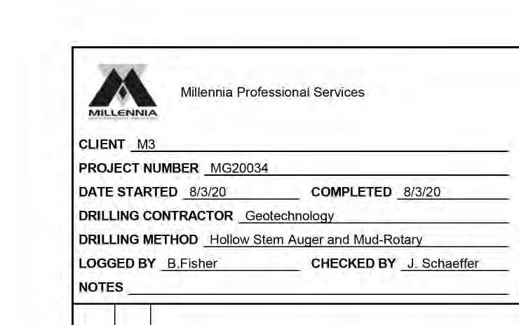
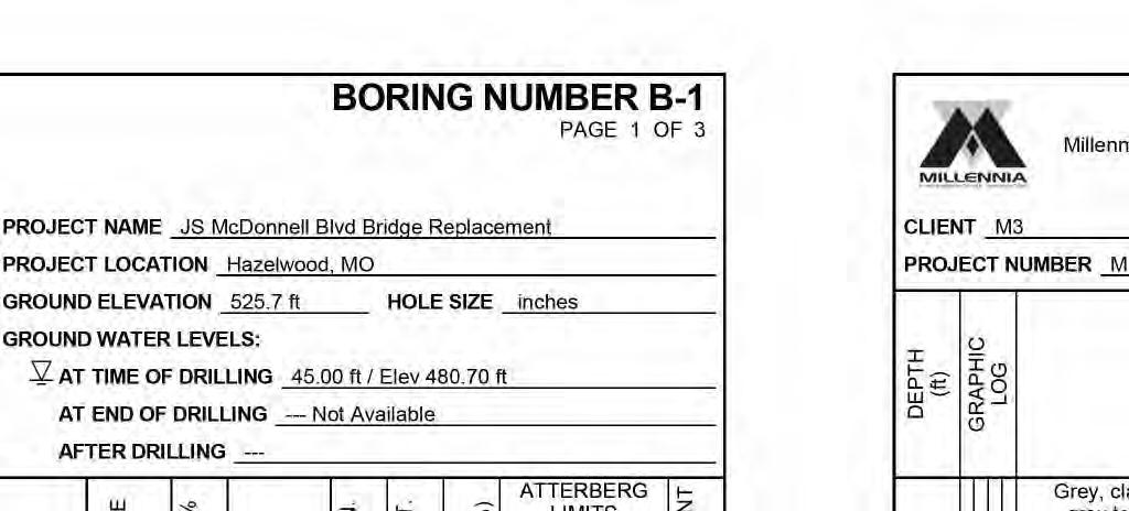
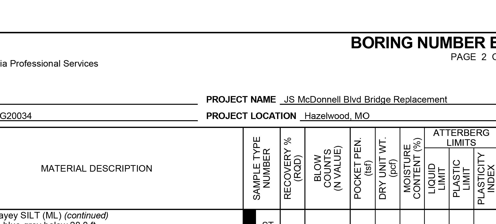


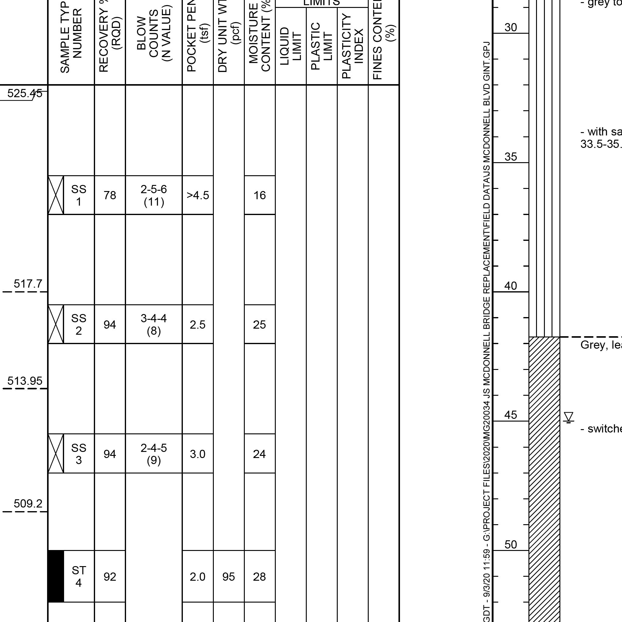
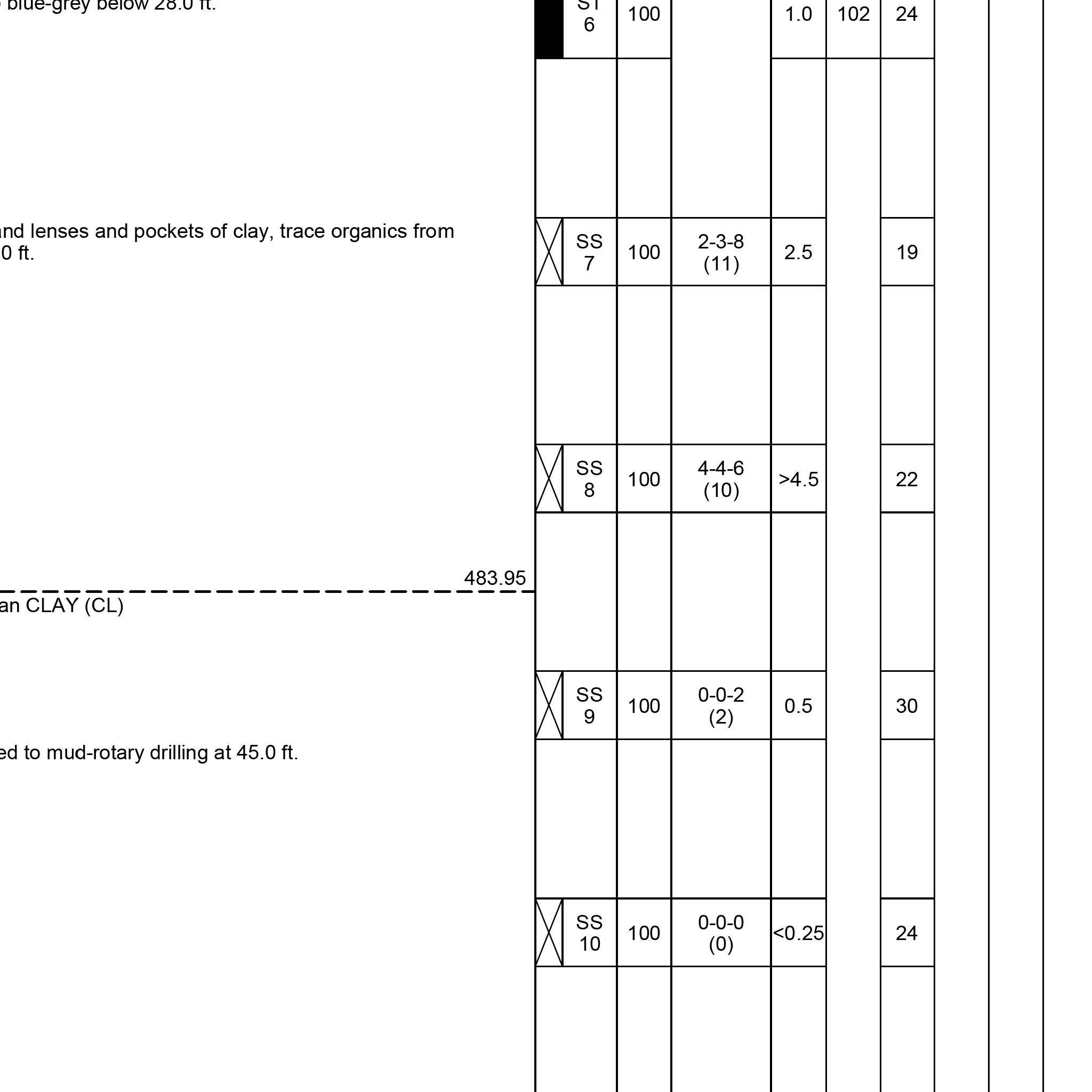
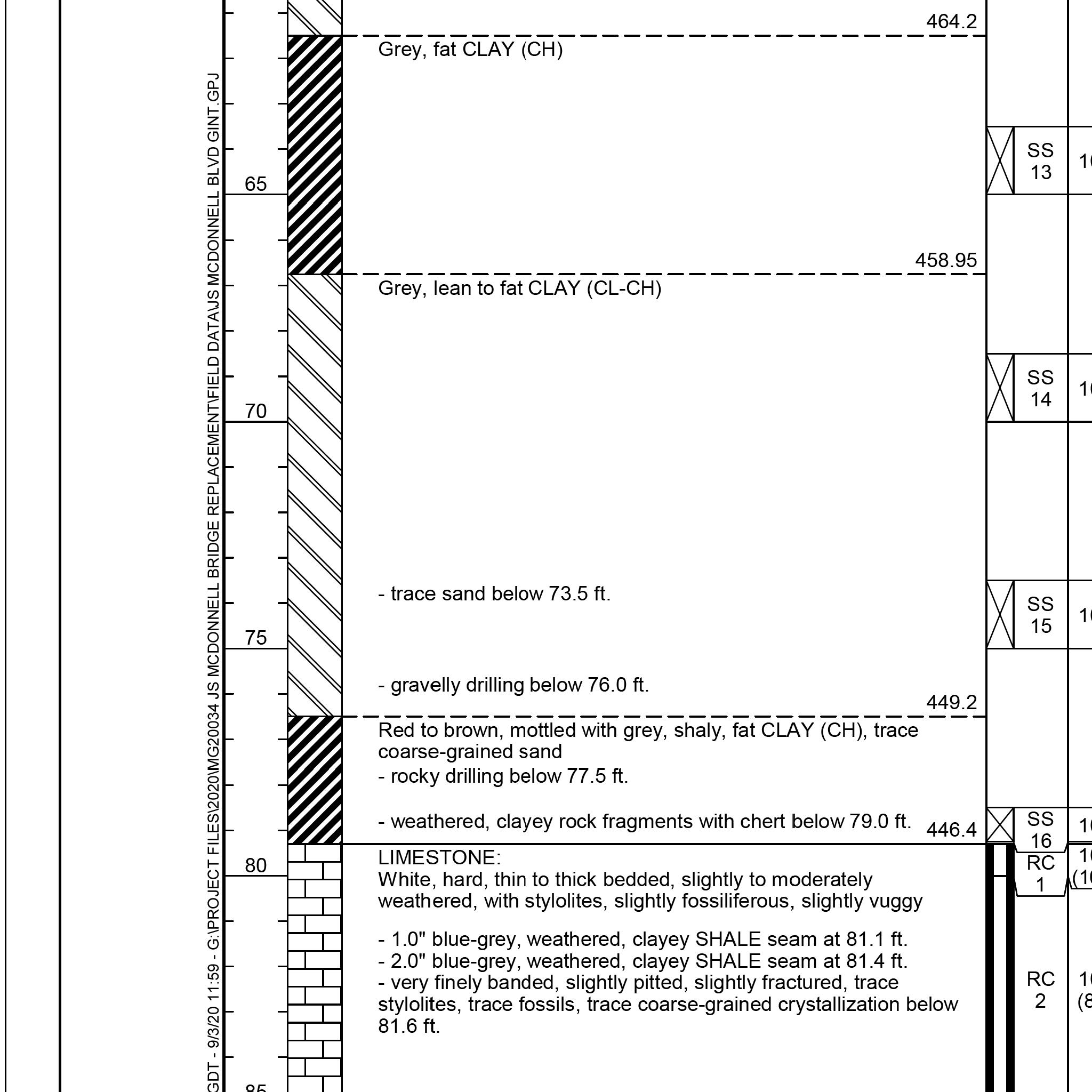
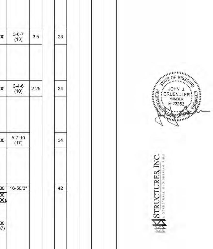
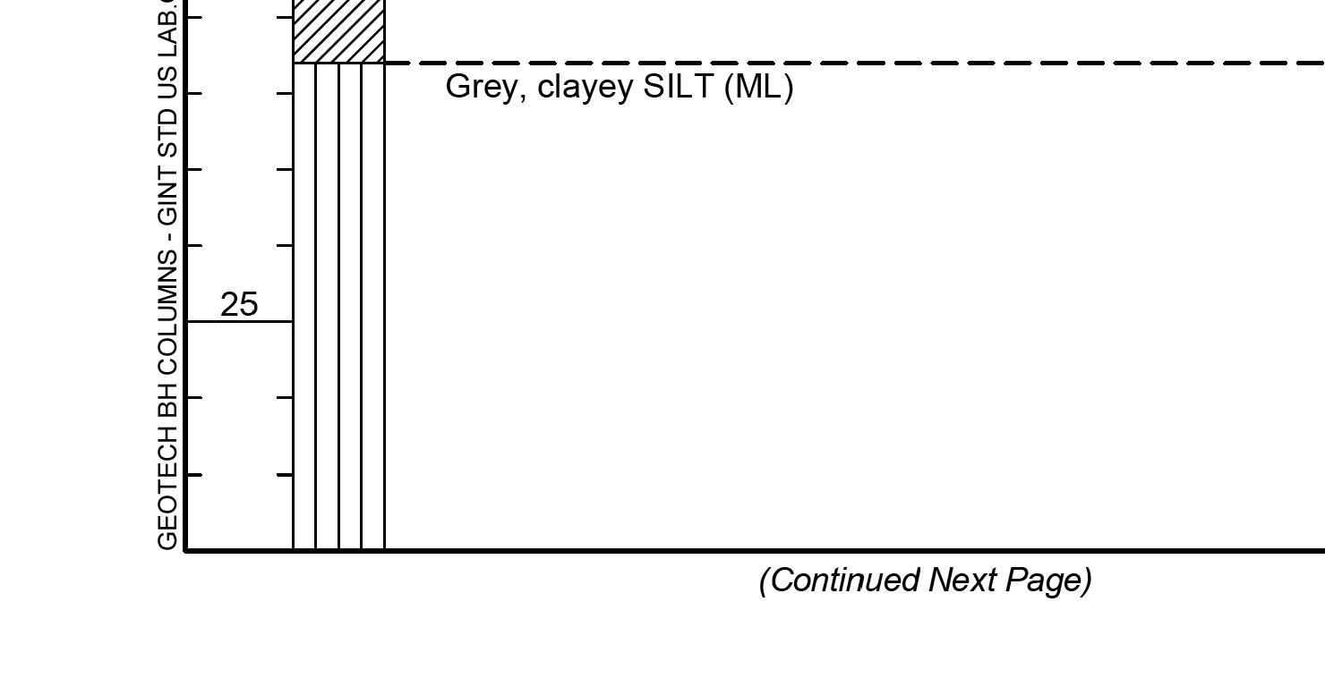
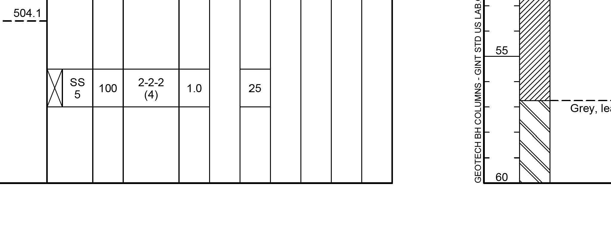
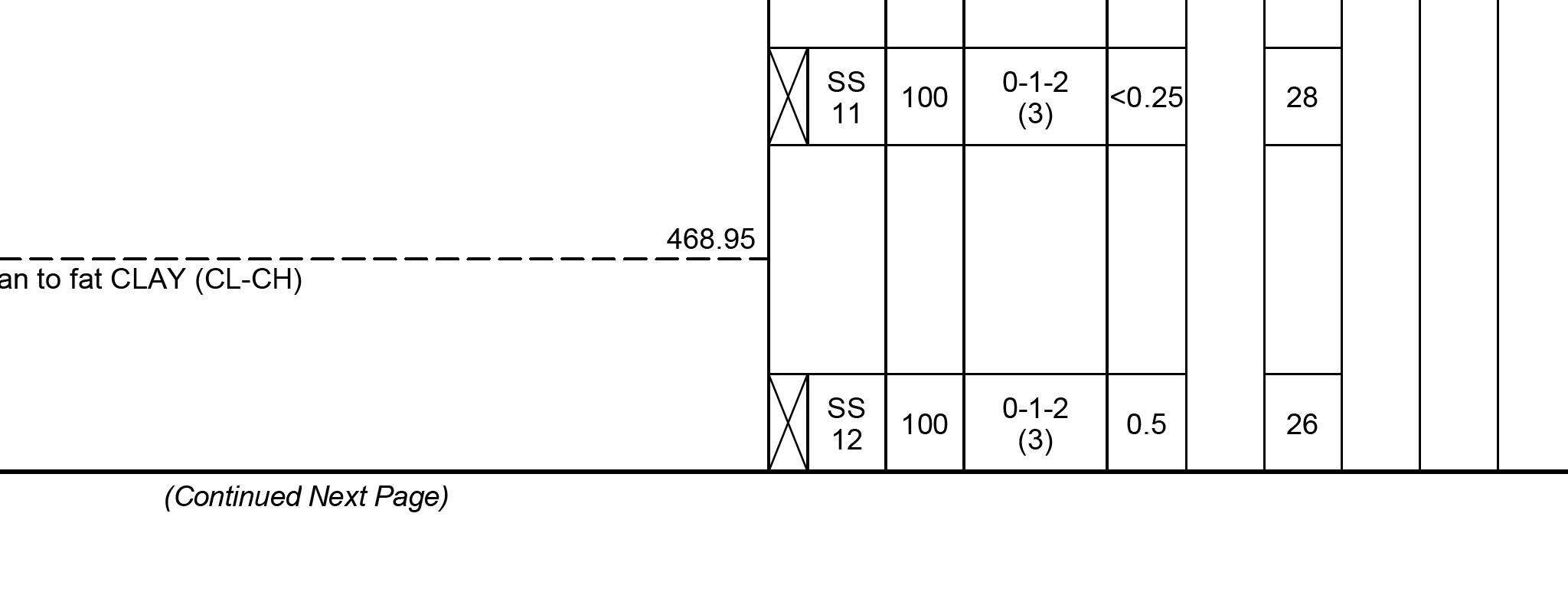
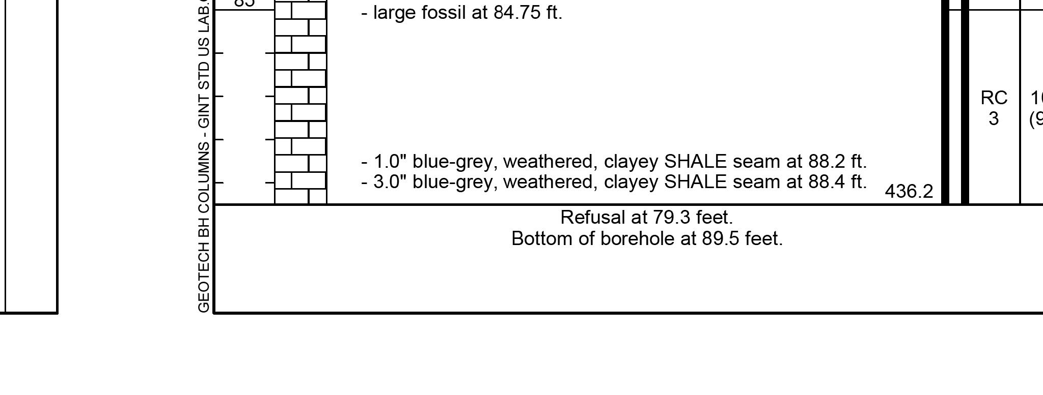
THIS DRAWING IS NOT TO SCALE, FOLLOW DIMENSIONS BORING LOGS FEDERAL PROJECT NO. SHEET SEQUENCE: COUNTY PROJECT NO. E-W GATEWAY TIP NO. REVISIONS REV. DATE BY APP. DESCRIPTION MSD BASE MAP: MSD: DRAWN: DATE: CHECKED: engineering project or survey used for any part of the relating to or intended to be documents or instruments Estimates, Reports or other Drawings, Specifications, responsibility for all other hereby disclaim any limited to this sheet, and I authorized by my seal are documents intended to be I hereby specify that the DESIGNED: RESPONSIBILITY ST. LOUIS COUNTY BRIDGE NO. MODOT BRIDGE NO. BRIDGE SHEET NO. PUBLIC WORKS TRANSPORTATION 096B164 164 J.J.G. R.S.N. J.J.G. 01/06/2023 MO PE NO. E-23263 PROFESSIONAL ENGINEER JOHN J. GRUENDLER NO. E-2006035000 CERTIFICATE OF AUTHORITY ST. LOUIS, MO 63126 11414 GRAVOIS RD, SUITE 201 20MSD-00355 52 OF 63 AR-1518 6905C-20 STP-4900(640) 40 OF 43 10K, 10L USACE contractor. prior to soil remediation work performed by Boring Log data shown represents conditions geotechnical report for additional data. See August 2020 Millennia Professional Services, For location of borings, see Bridge Sheet No. 1. BRIDGE NO. 164 J.S. MCDONNELL BLVD. 1/3/2023 1:49:44 PM

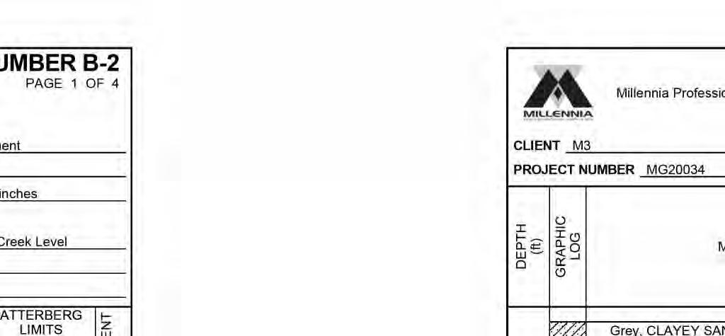
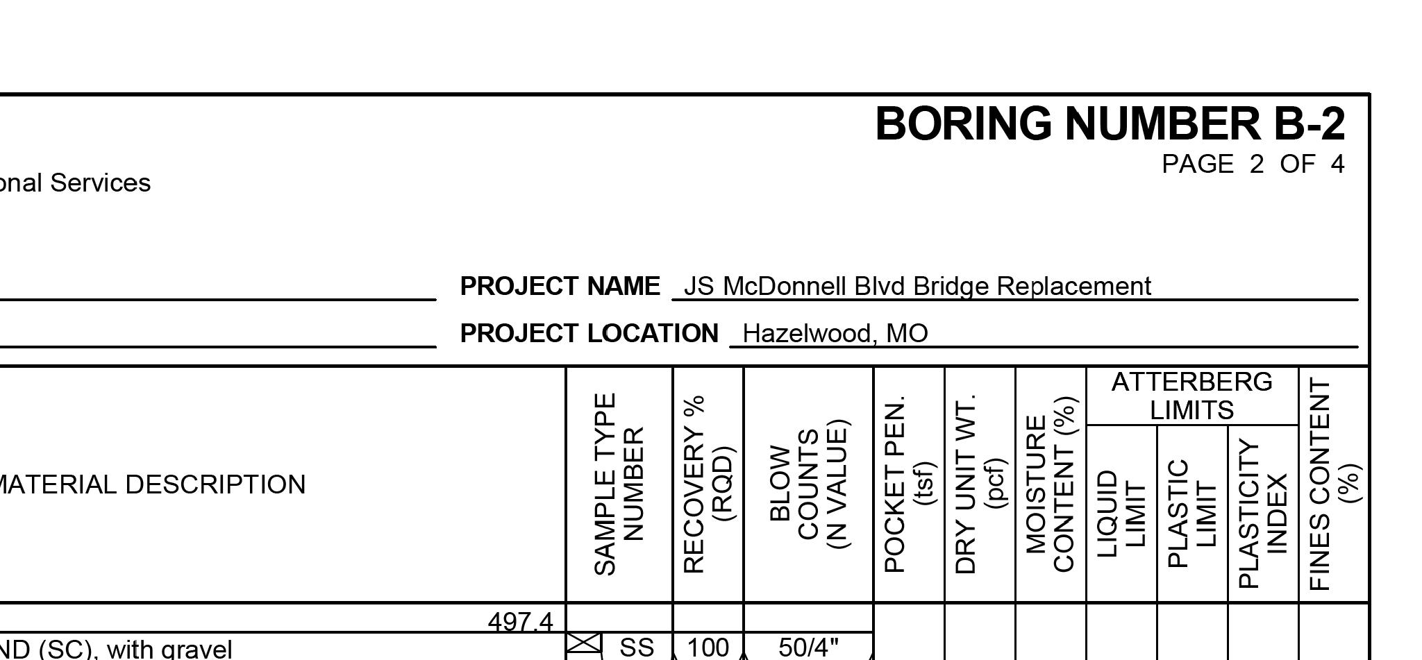
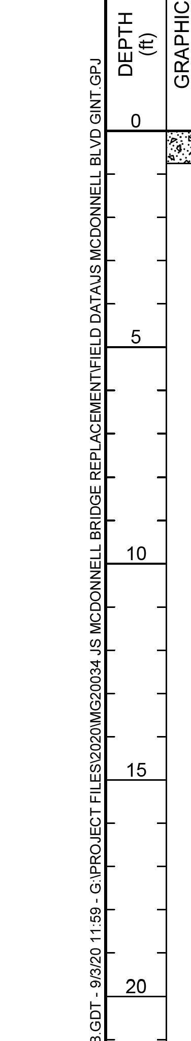
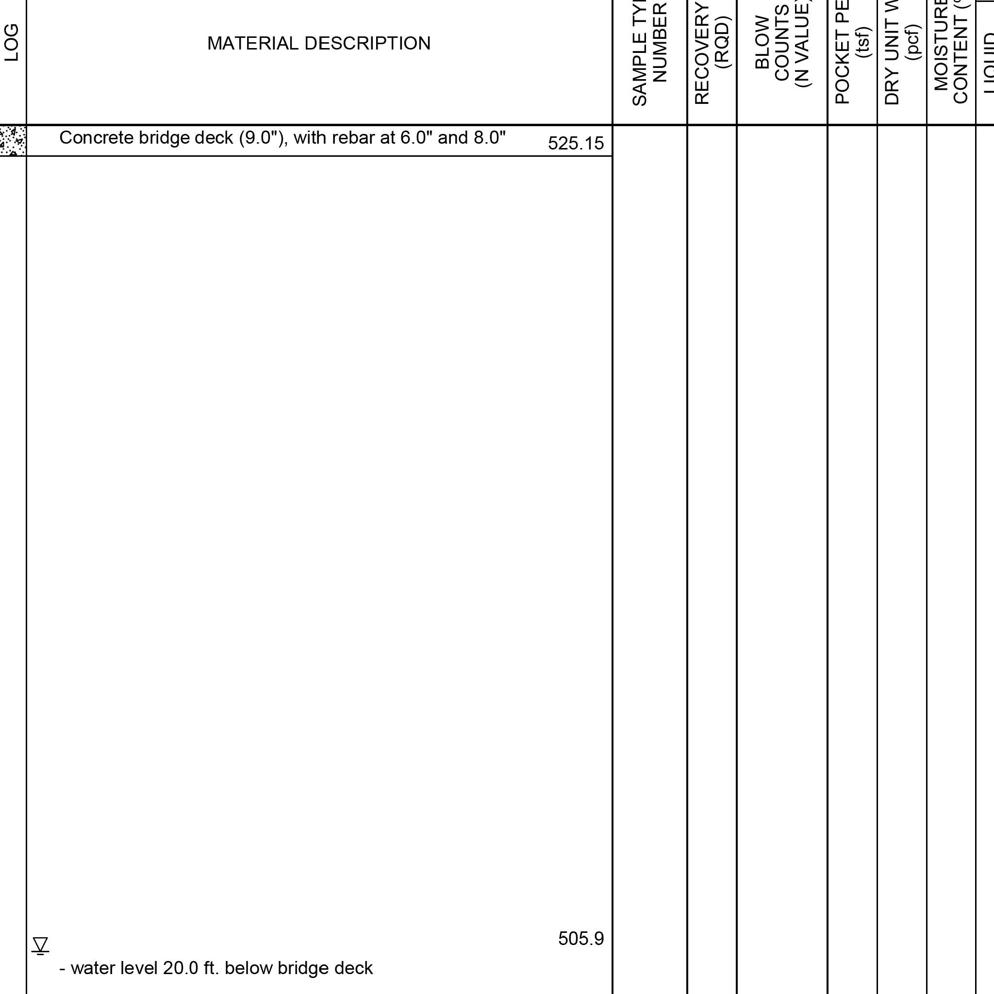
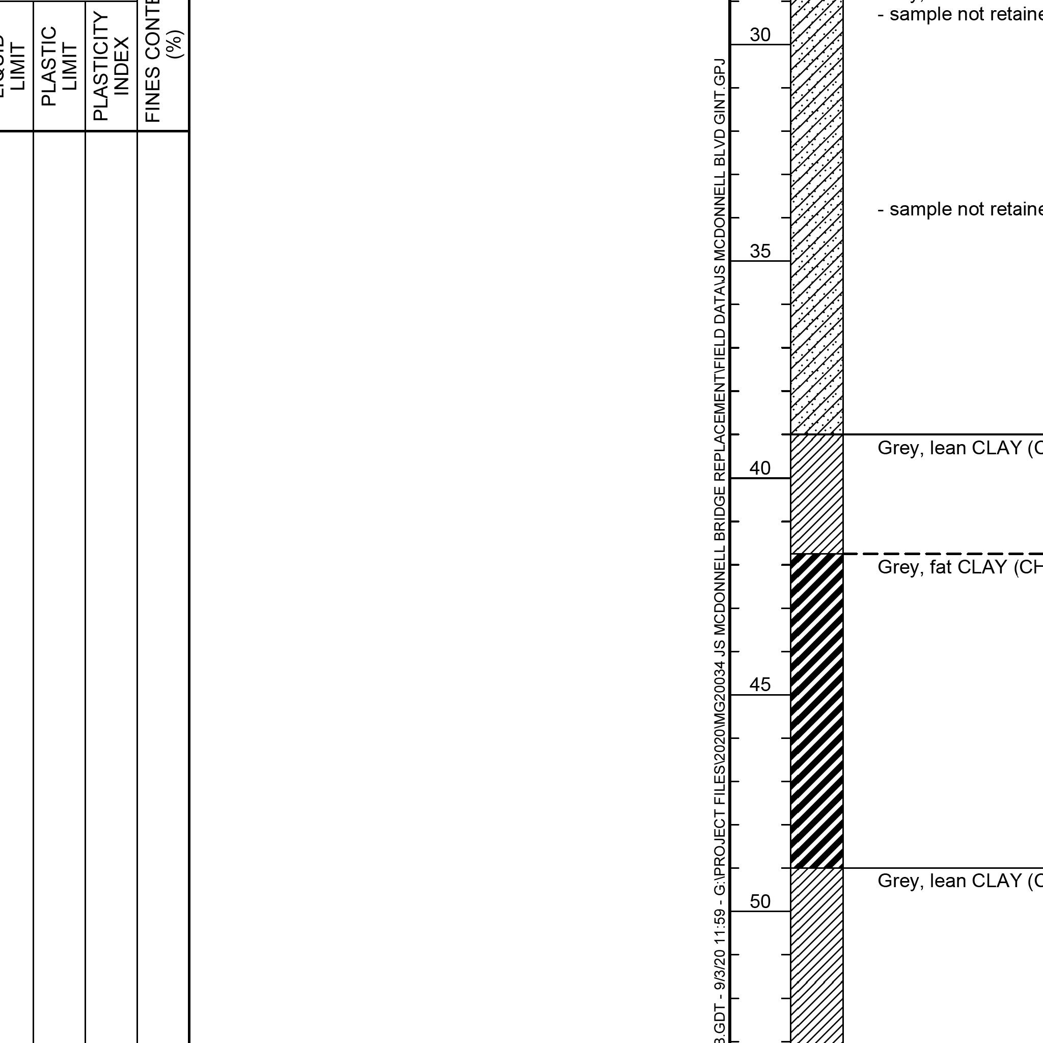
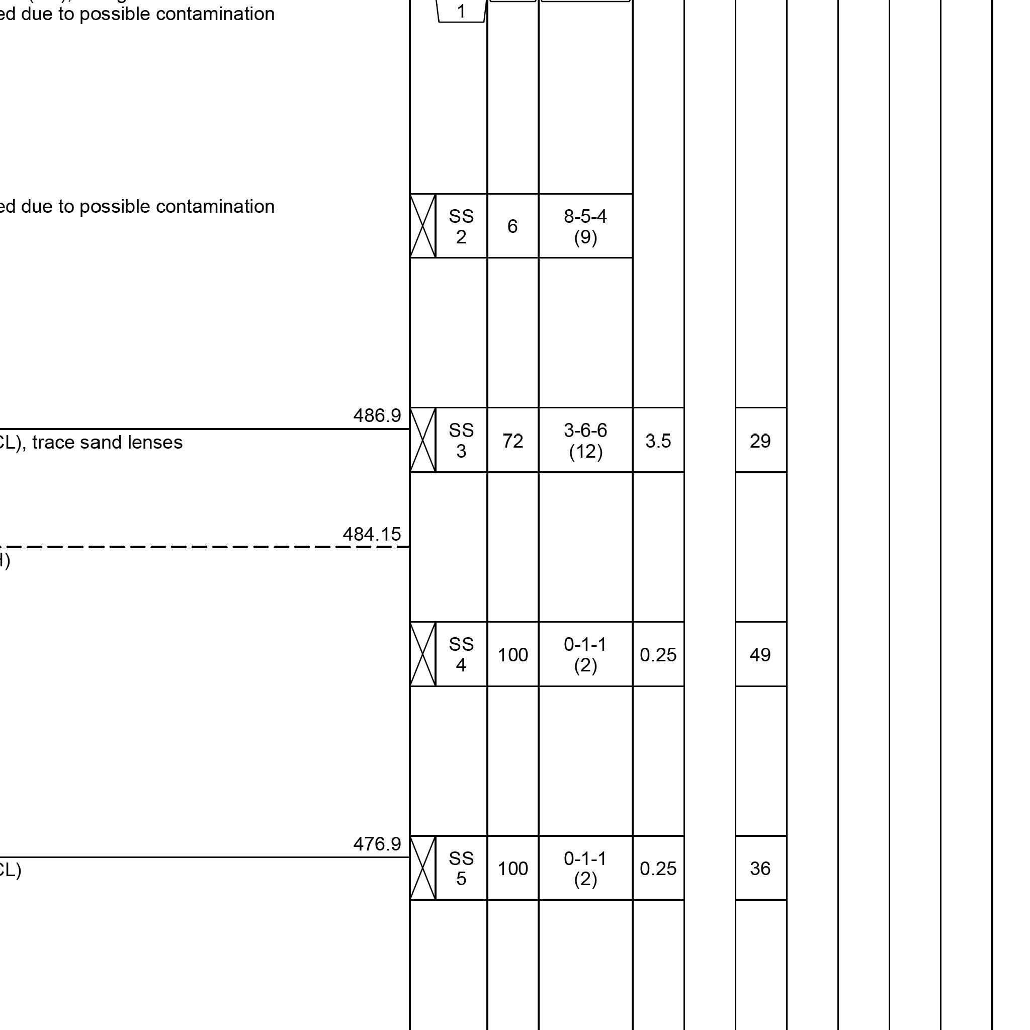
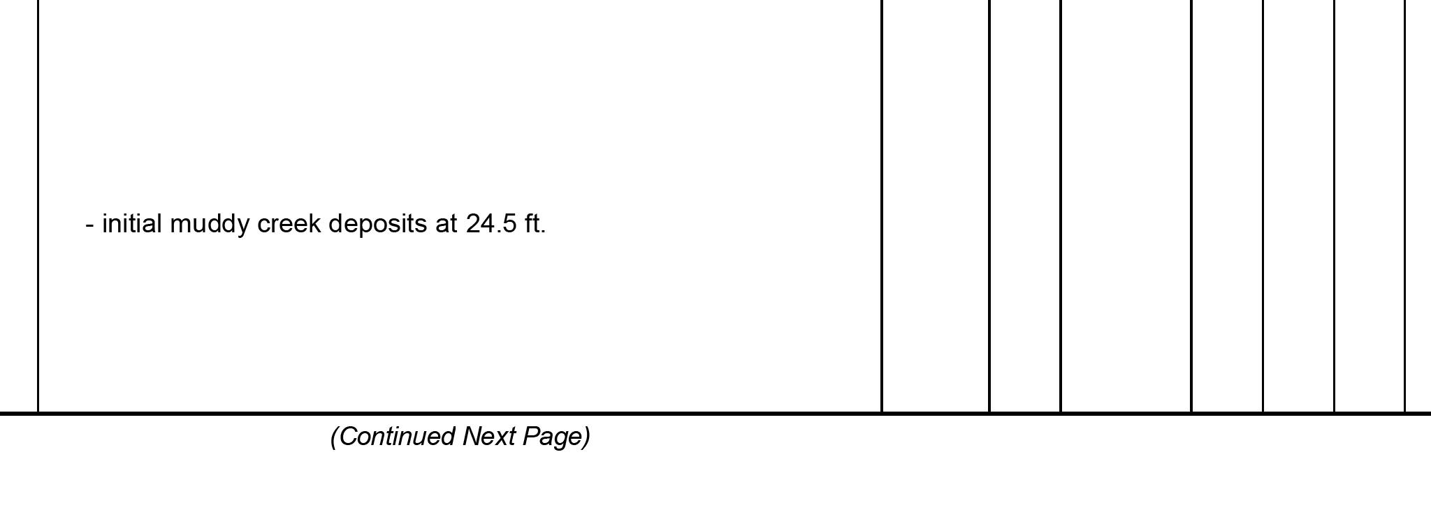
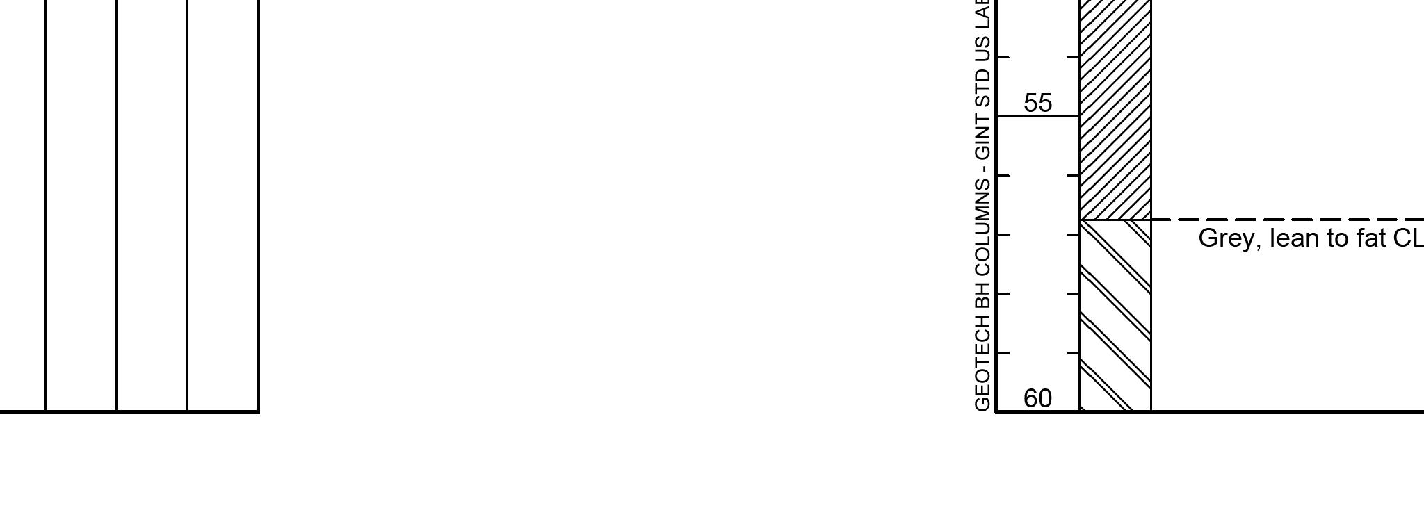
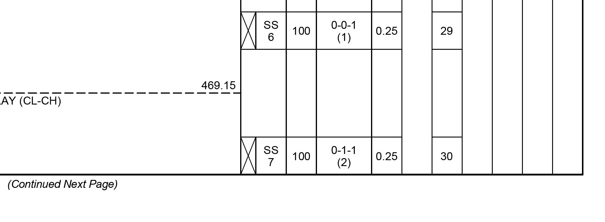
THIS DRAWING IS NOT TO SCALE, FOLLOW DIMENSIONS BORING LOGS FEDERAL PROJECT NO. SHEET SEQUENCE: COUNTY PROJECT NO. E-W GATEWAY TIP NO. REVISIONS REV. DATE BY APP. DESCRIPTION MSD BASE MAP: MSD: DRAWN: DATE: CHECKED: engineering project or survey used for any part of the relating to or intended to be documents or instruments Estimates, Reports or other Drawings, Specifications, responsibility for all other hereby disclaim any limited to this sheet, and I authorized by my seal are documents intended to be I hereby specify that the DESIGNED: RESPONSIBILITY ST. LOUIS COUNTY BRIDGE NO. MODOT BRIDGE NO. BRIDGE SHEET NO. PUBLIC WORKS TRANSPORTATION 096B164 164 J.J.G. R.S.N. J.J.G. 01/06/2023 MO PE NO. E-23263 PROFESSIONAL ENGINEER JOHN J. GRUENDLER NO. E-2006035000 CERTIFICATE OF AUTHORITY ST. LOUIS, MO 63126 11414 GRAVOIS RD, SUITE 201 20MSD-00355 53 OF 63 AR-1518 6905C-20 STP-4900(640) 41 OF 43 10K, 10L USACE contractor. prior to soil remediation work performed by Boring Log data shown represents conditions geotechnical report for additional data. See August 2020 Millennia Professional Services, For location of borings, see Bridge Sheet No. 1. BRIDGE NO. 164 J.S. MCDONNELL BLVD. 1/3/2023 1:50:52 PM
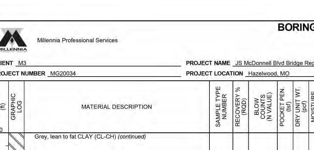
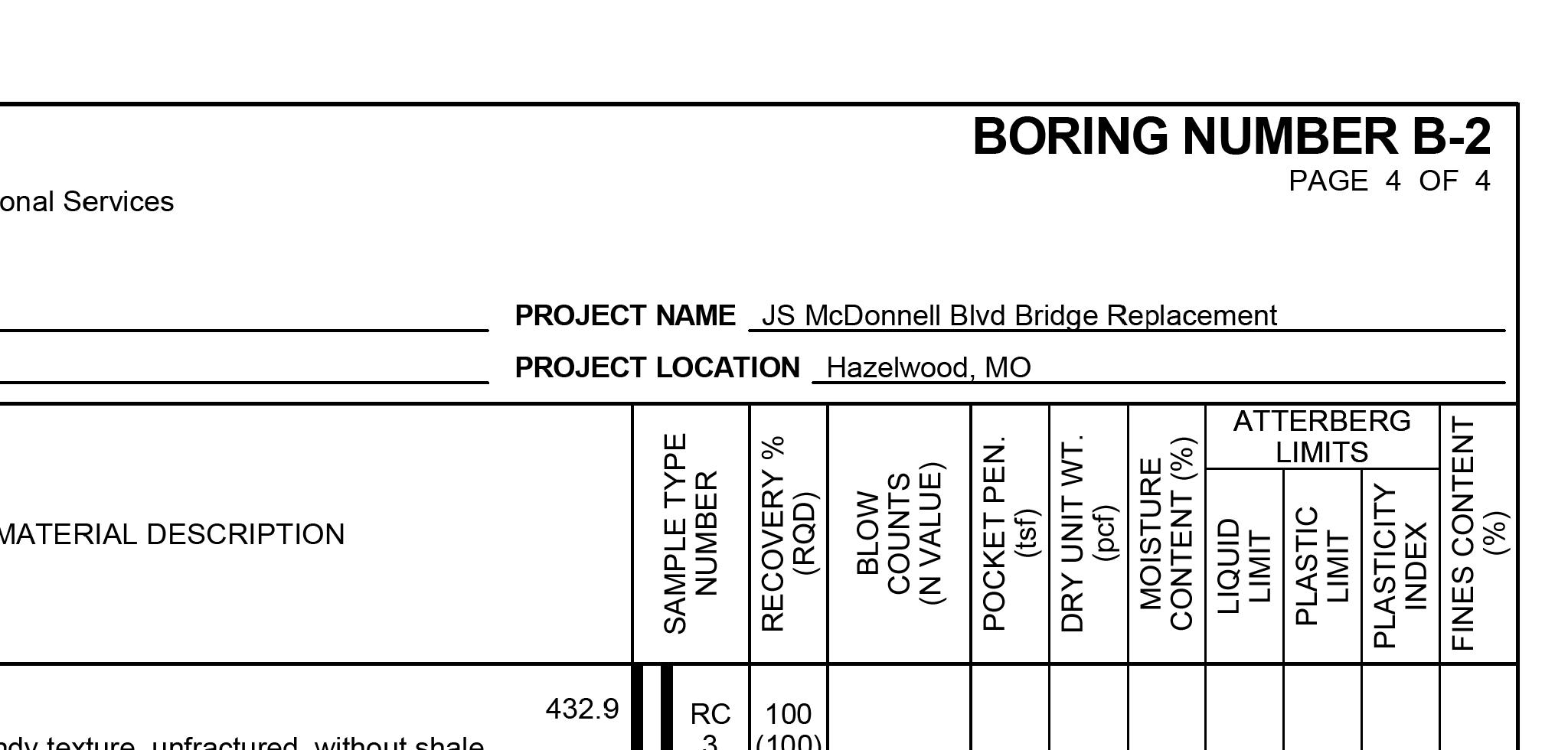
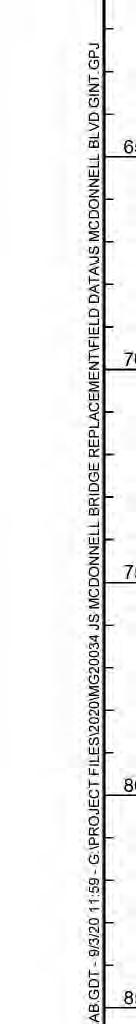
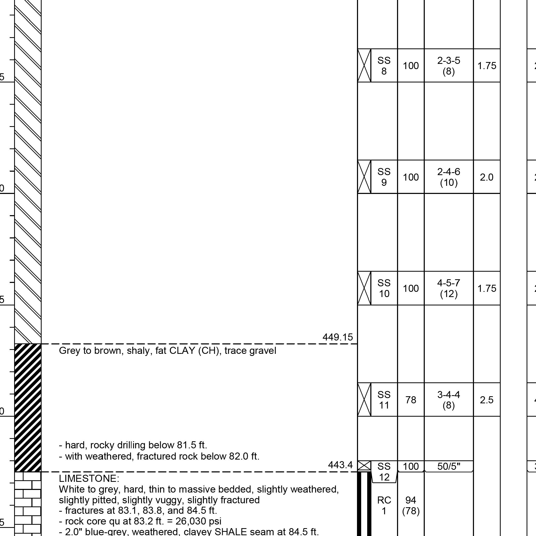
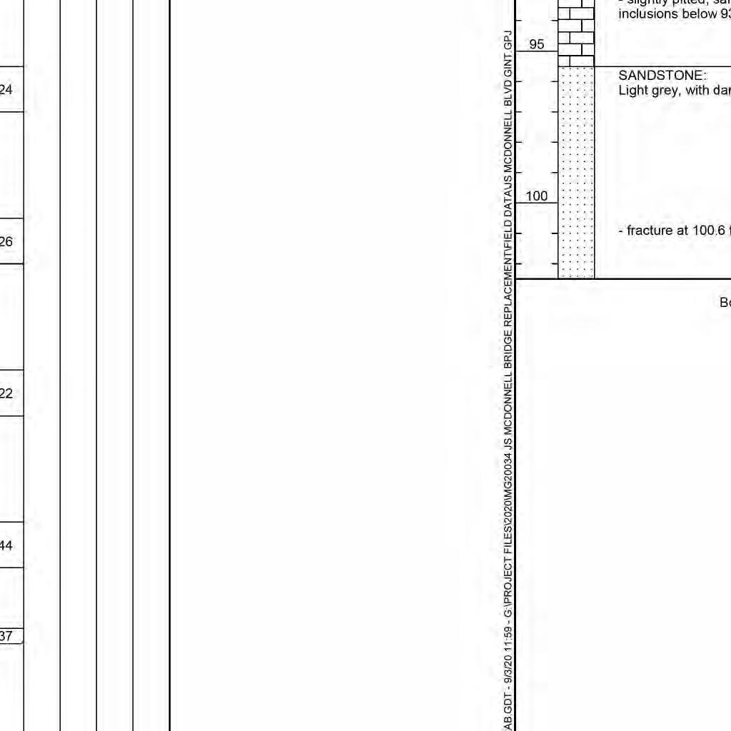
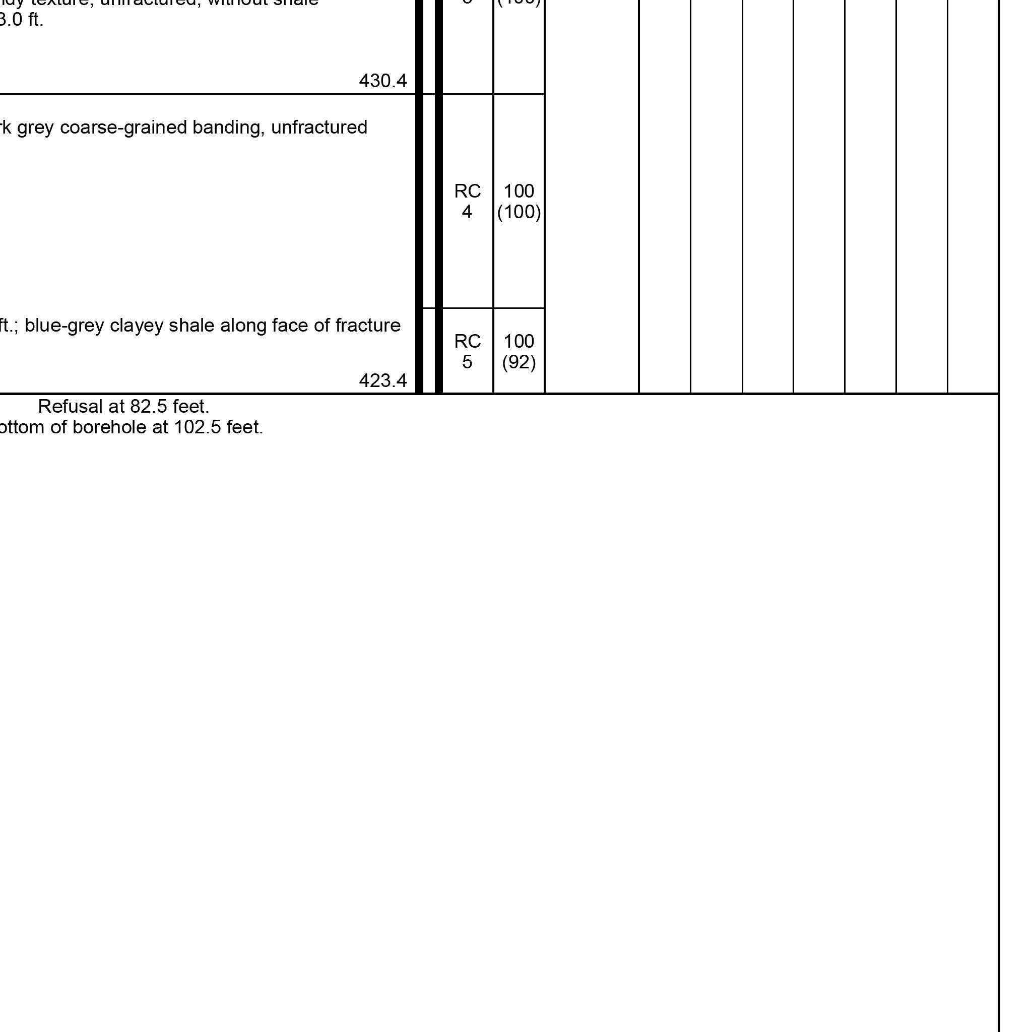
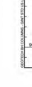
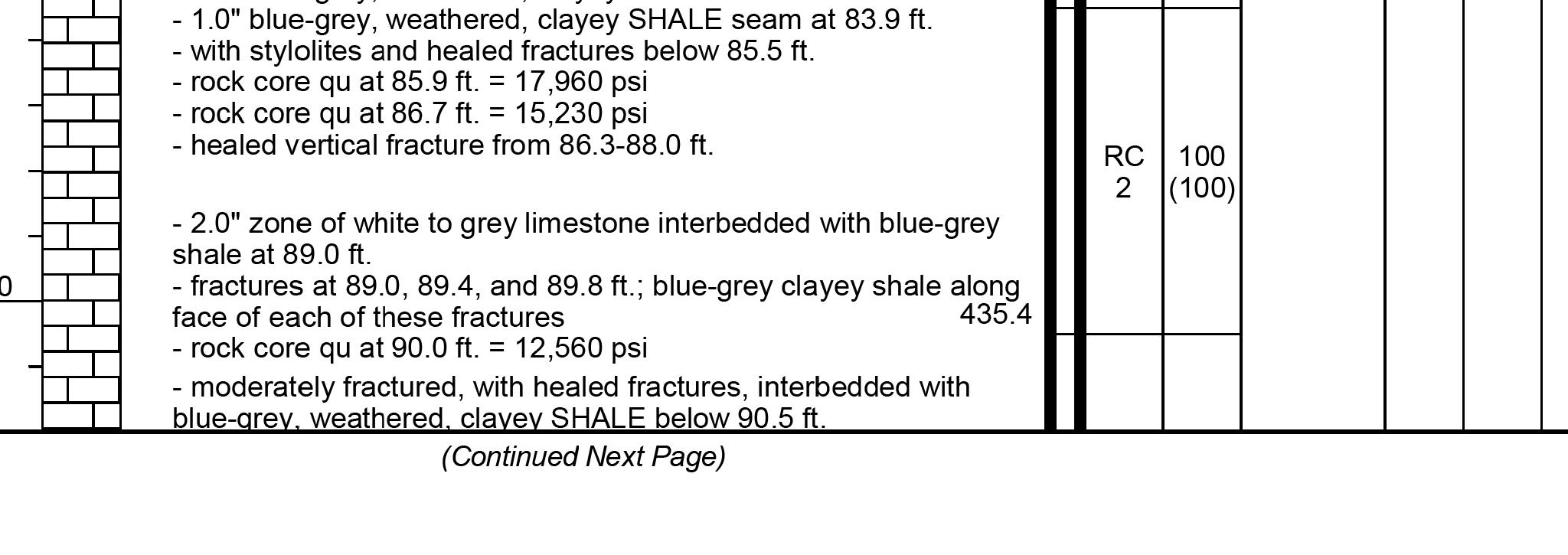
THIS DRAWING IS NOT TO SCALE, FOLLOW DIMENSIONS BORING LOGS FEDERAL PROJECT NO. SHEET SEQUENCE: COUNTY PROJECT NO. E-W GATEWAY TIP NO. REVISIONS REV. DATE BY APP. DESCRIPTION MSD BASE MAP: MSD: DRAWN: DATE: CHECKED: engineering project or survey used for any part of the relating to or intended to be documents or instruments Estimates, Reports or other Drawings, Specifications, responsibility for all other hereby disclaim any limited to this sheet, and I authorized by my seal are documents intended to be I hereby specify that the DESIGNED: RESPONSIBILITY ST. LOUIS COUNTY BRIDGE NO. MODOT BRIDGE NO. BRIDGE SHEET NO. PUBLIC WORKS TRANSPORTATION 096B164 164 J.J.G. R.S.N. J.J.G. 01/06/2023 MO PE NO. E-23263 PROFESSIONAL ENGINEER JOHN J. GRUENDLER NO. E-2006035000 CERTIFICATE OF AUTHORITY ST. LOUIS, MO 63126 11414 GRAVOIS RD, SUITE 201 20MSD-00355 AR-1518 6905C-20 STP-4900(640) 42 OF 43 10K, 10L USACE contractor. prior to soil remediation work performed by Boring Log data shown represents conditions geotechnical report for additional data. See August 2020 Millennia Professional Services, For location of borings, see Bridge Sheet No. 1. BRIDGE NO. 164 J.S. MCDONNELL BLVD. 54 OF 63 1/3/2023 1:51:54 PM


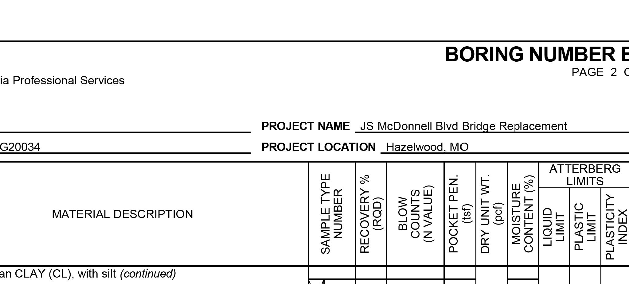
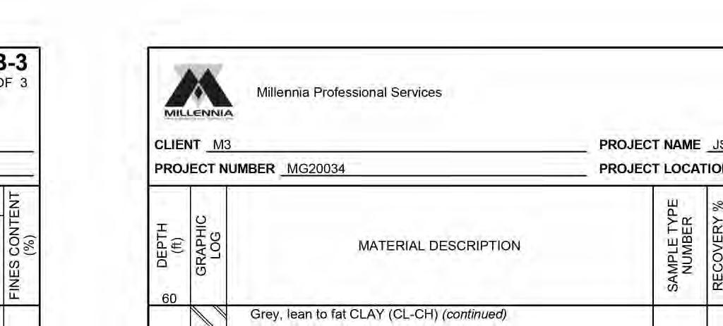
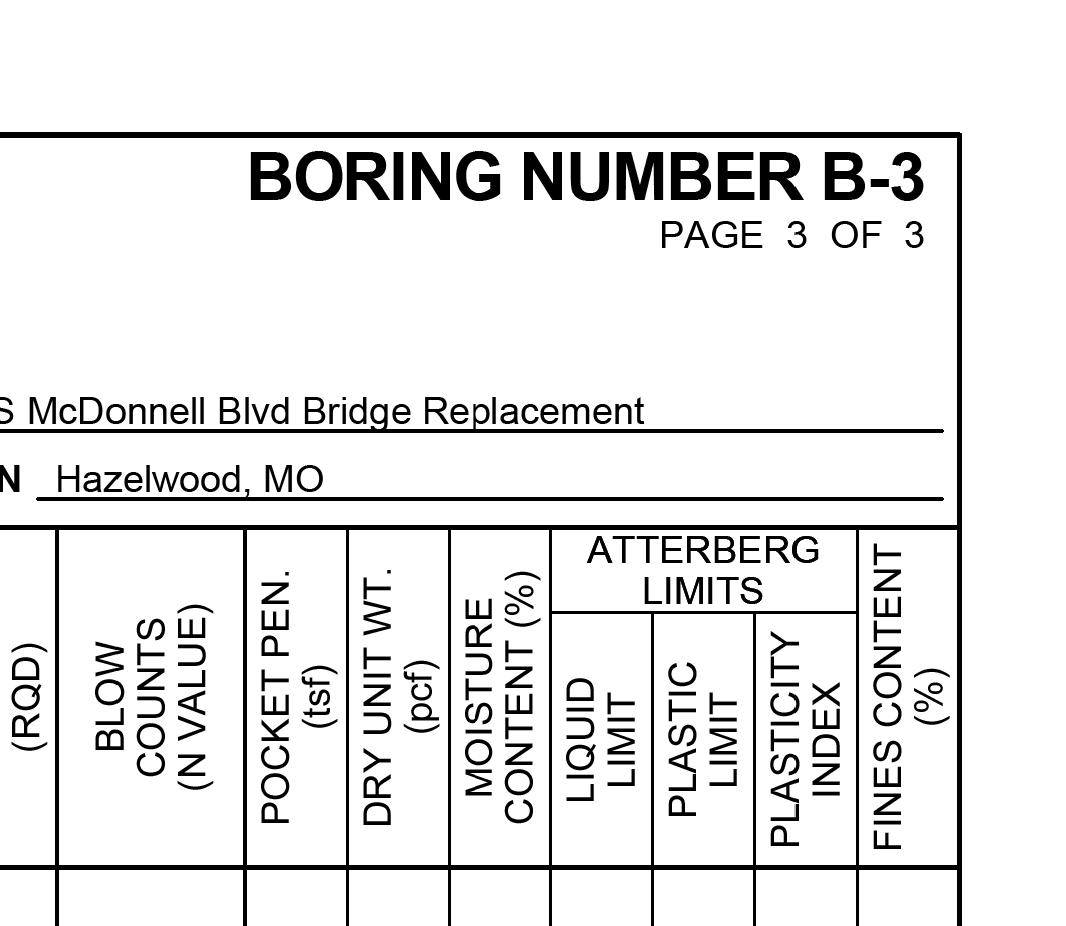
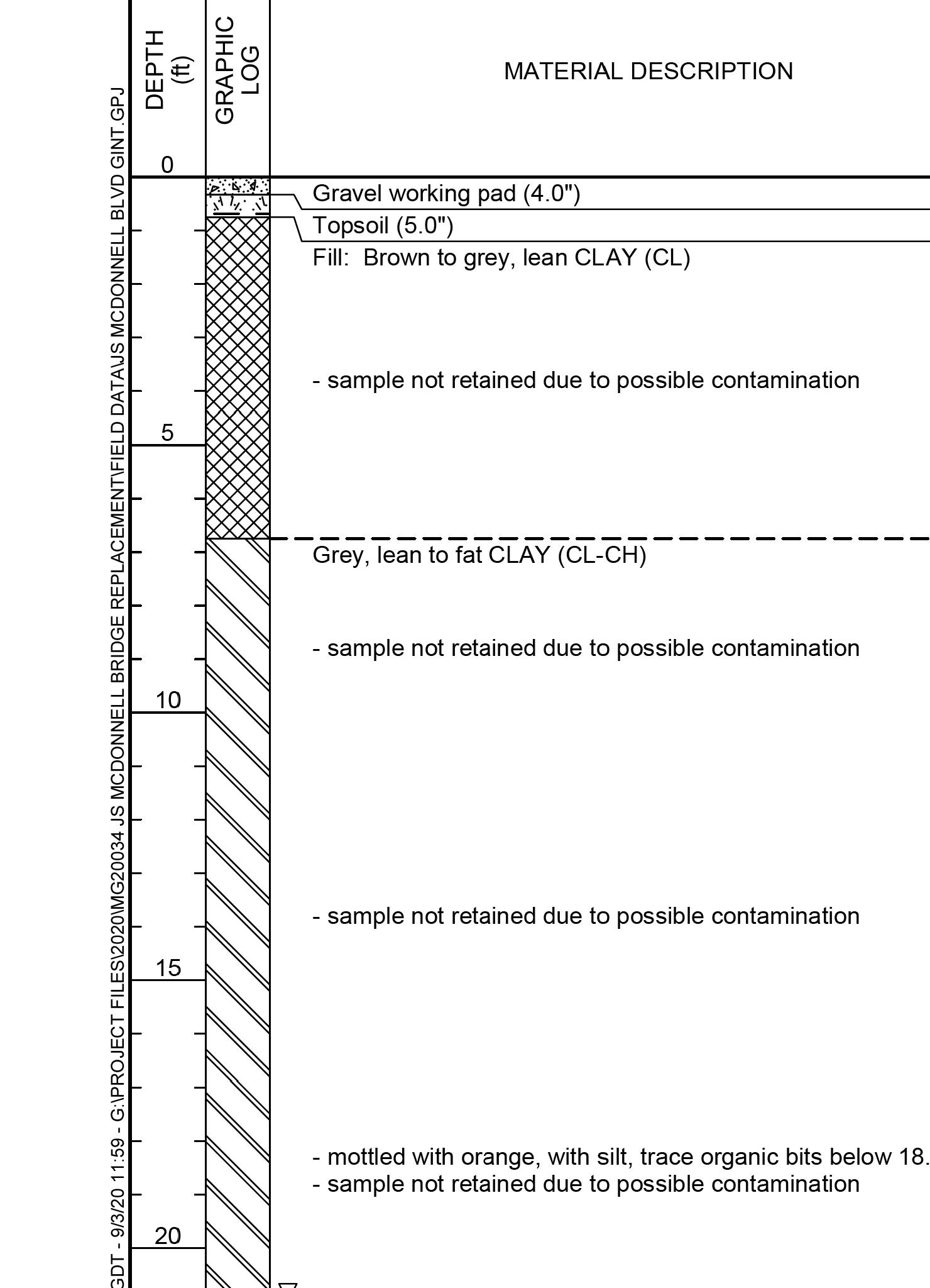
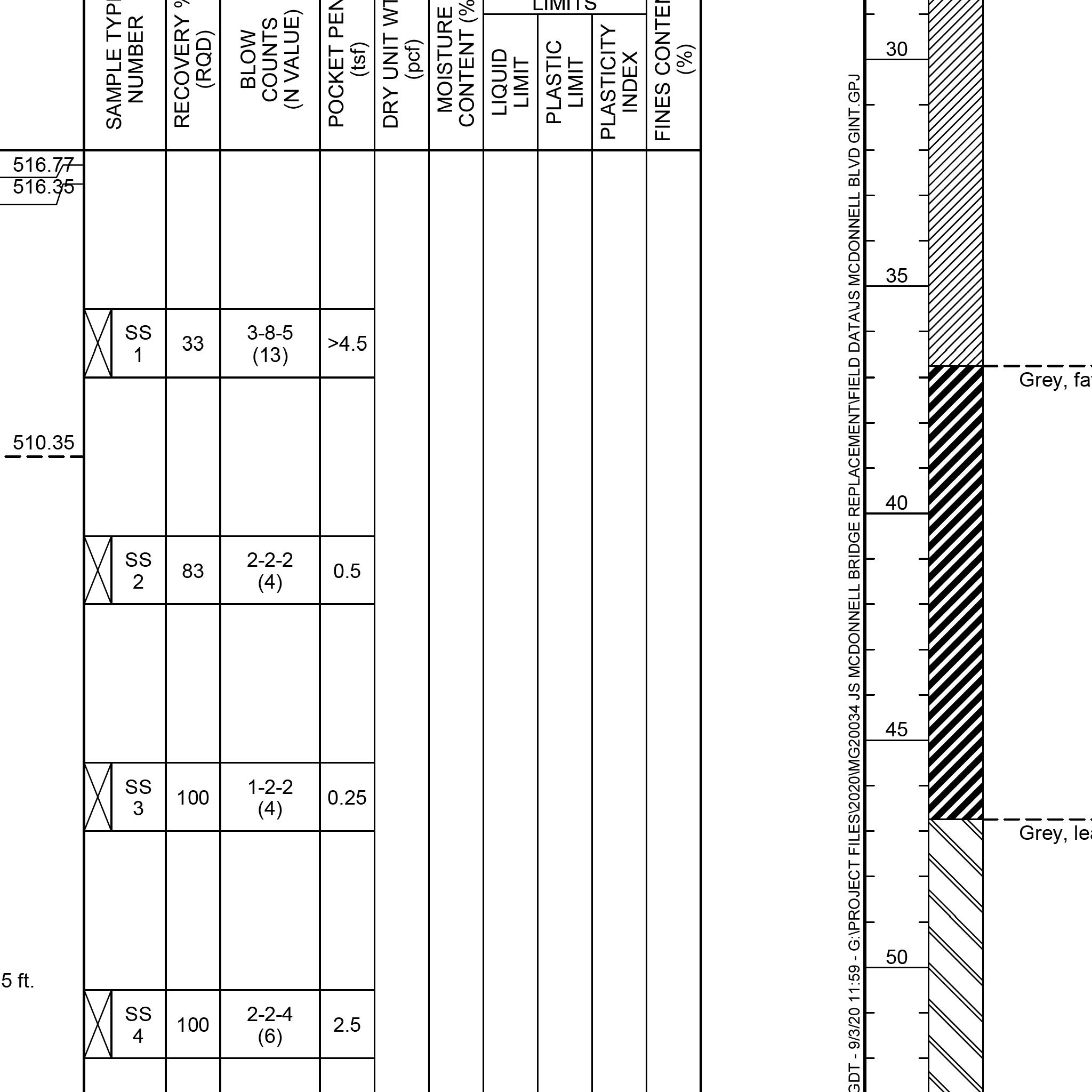
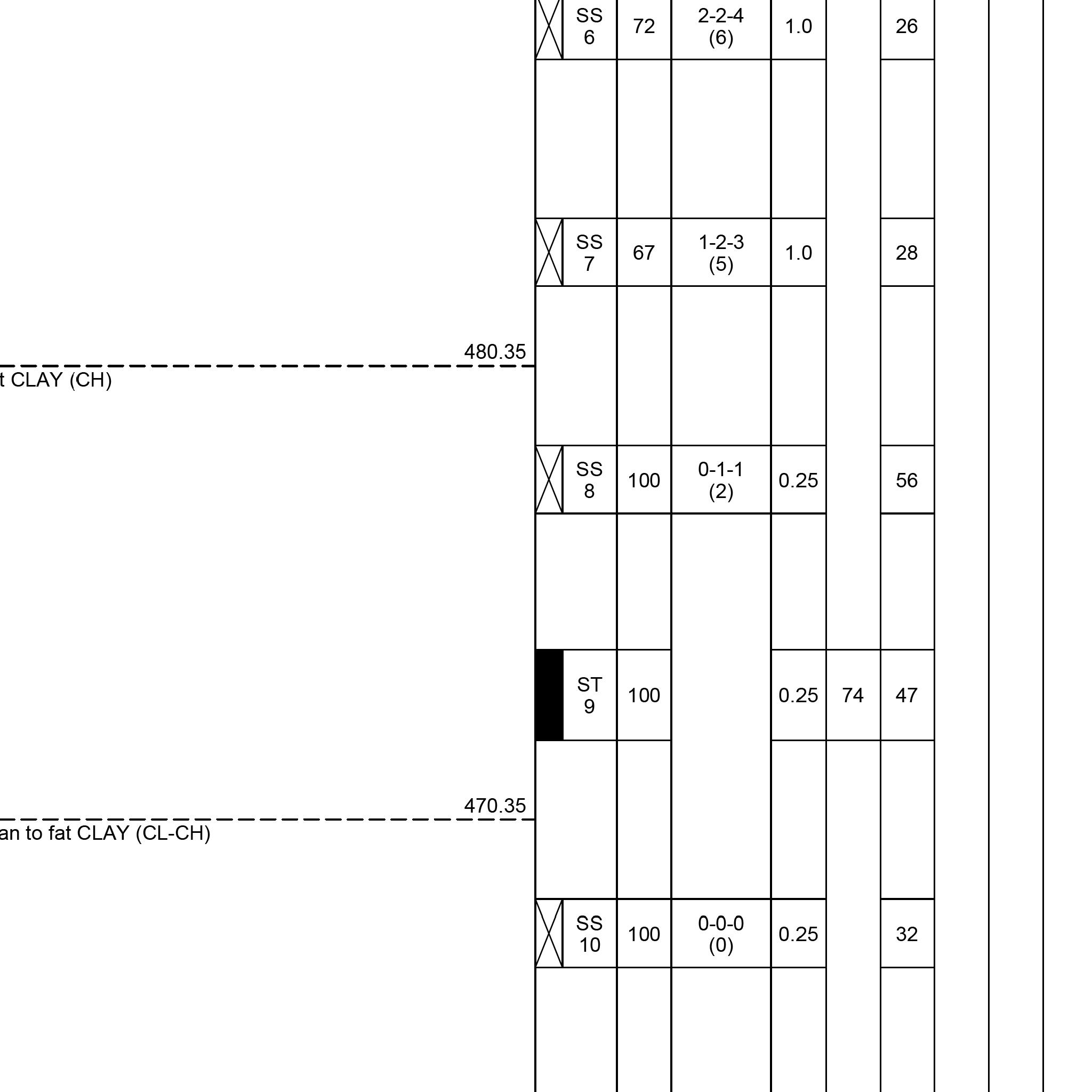
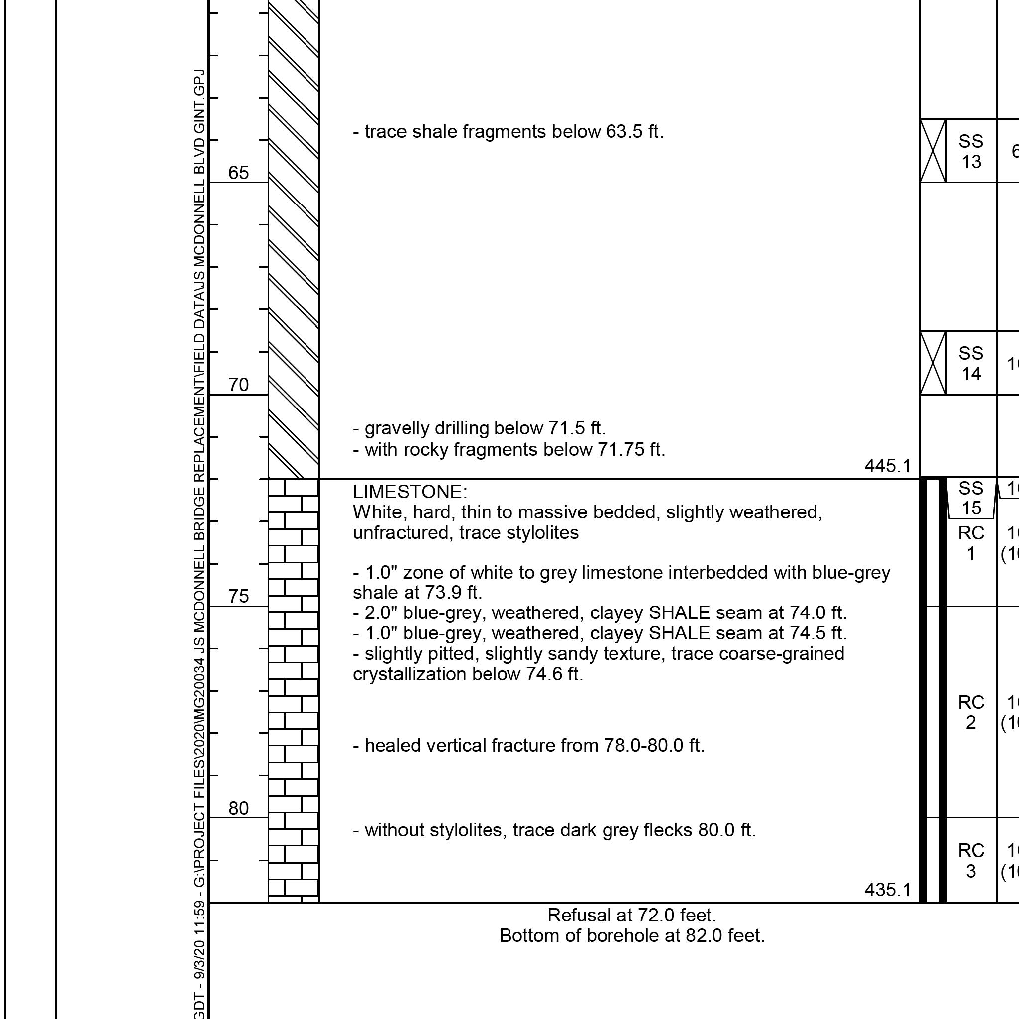
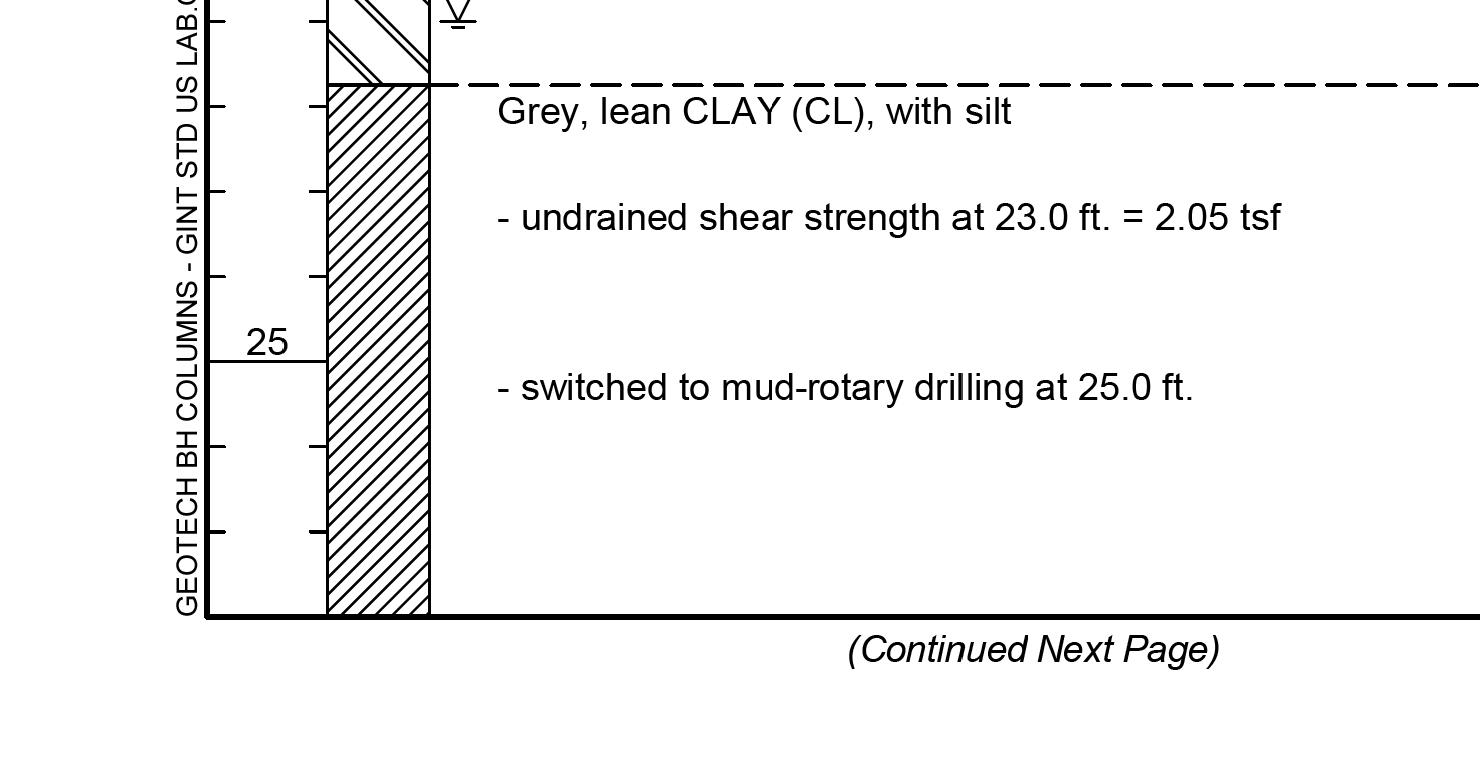
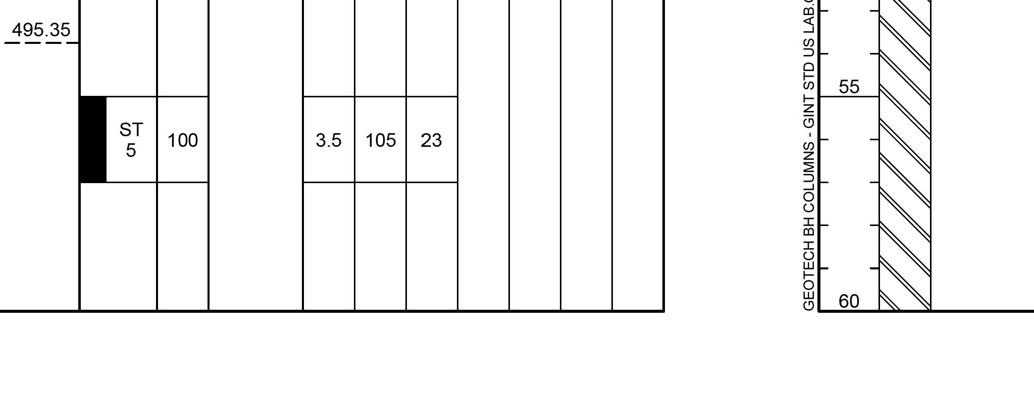

THIS DRAWING IS NOT TO SCALE, FOLLOW DIMENSIONS BORING LOGS FEDERAL PROJECT NO. SHEET SEQUENCE: COUNTY PROJECT NO. E-W GATEWAY TIP NO. REVISIONS REV. DATE BY APP. DESCRIPTION MSD BASE MAP: MSD: DRAWN: DATE: CHECKED: engineering project or survey used for any part of the relating to or intended to be documents or instruments Estimates, Reports or other Drawings, Specifications, responsibility for all other hereby disclaim any limited to this sheet, and I authorized by my seal are documents intended to be I hereby specify that the DESIGNED: RESPONSIBILITY ST. LOUIS COUNTY BRIDGE NO. MODOT BRIDGE NO. BRIDGE SHEET NO. PUBLIC WORKS TRANSPORTATION 096B164 164 J.J.G. R.S.N. J.J.G. 01/06/2023 MO PE NO. E-23263 PROFESSIONAL ENGINEER JOHN J. GRUENDLER NO. E-2006035000 CERTIFICATE OF AUTHORITY ST. LOUIS, MO 63126 11414 GRAVOIS RD, SUITE 201 20MSD-00355 55 OF 63 AR-1518 6905C-20 STP-4900(640) 43 OF 43 10K, 10L USACE contractor. prior to soil remediation work performed by Boring Log data shown represents conditions geotechnical report for additional data. See August 2020 Millennia Professional Services, For location of borings, see Bridge Sheet No. 1. BRIDGE NO. 164 J.S. MCDONNELL BLVD. 1/3/2023 1:52:54 PM
V C P ( U I P ) C L 60
32 56
LT ELE V 523 27
ELE V 525 22 30 66
R T ELE V 526 21 E X 525 20 C L 8
50%
23 78
E X R / W E X R / W 4:1
R T V 526 42 30% P G
4:1 60%
28+50.00
V C P ( U I P ) C L 60
i f t h t t h R E SP ON S I B I L I T Y S C A
nd a u t ho r i ze d by m y s ea l a r e do c u m e n t s i n t e nd e d t o b e I h
ELE V 525 09 30 72
E X R / W E X R / W 32 73
R T E X 525 09 (MATCHVAEXISTING) RIES (MATCHVAEXISTING) RIES M A T C H E X A C M A T C H E X C L 8

RC P ( U I P )
LT 23 78

R T P G
28+43.57
V C P ( U I P ) C L 60
RC P ( U I P ) EXISTING GRADE (PHASE 3) (TYP) 28+25.00

RC P ( U I P ) (TBR&R.BO)EXISTING PAVEMENT
28+50.00 28+43.57 28+25.00
h i h
ny li it d
by DESIGNED:
by d i l i
ll t h h
i f i ti pon i b ility f
i
O P U B L I C W O R K S T R AN SP O R T A T I ON
BR I DG E NO 164 J S M C DONN ELL B L VD
S
20MSD-00355 NO E2009027953 C E R T I F I C A TE O F AU T HO R I T Y S T L OU I S M O 63101 911 W A S H I NG T ON AV E S TE 620 E X R / W E X R / W E X 524 68 C L 8
b E s ti m a t e s R e po r t s o r o t h e r D
i
nd d
f h l ting
j t d f
STP-4900(640) 6905C-20 10K, 10L 01/06/2023 L I C E N S E NO 023795 P R O F E SS I ONA L E NG I N EE R M A RC W E S H EL M AN M.W.E. M.R.B. M.S.M. OF 63
i
ny p
535 530 525 520 520 525 530 535 520 525 530 535 535 530 525 520 535 530 525 520 535 530 525 520 CONSTRUCTION -10 -20 -30 -40 -50 -60 -70 -80 -90 -100 -110 -120 -130 -140 10 20 30 40 50 60 70 80 90 100 110 120 130 140 ( S H EET 1 O F 8 ) CR O SS S E C T I ON S 515 515 515 515 515 515 56 FEDERAL PROJECT NO. AR-1518 SHEET SEQUENCE: COUNTY PROJECT NO. E-W GATEWAY TIP NO. R E V I S I ON S R E V DA TE B Y A PP D E S CR I P T I ON MSD BASE MAP: MSD: DRAWN: DATE: CHECKED:
i
ELE V 527 46 E X 526 68 4:1
LT ELE V 525 76 23 95
R T ELE V 528 84 29 42
R T ELE V 528 73 P G
5.8% 20% E X R / W E X R / W C L 8
28 44
4:1 60%
V C P ( U I P ) C L 18
30+00.00
V C P ( U I P ) C L 60
i f t h t t h R E SP ON S I B I L I T Y S C A
nd a u t ho r i ze d by m y s ea l a r e do c u m e n t s i n t e nd e d t o b e I h
ELE V 527 19 E X 526 54 4:1
29 13
LT ELE V 525 44 23 92
R T ELE V 528 42 P G
R T ELE V 528 54 29 62
5.6% 20% E X R / W E X R / W C L 8
V C P ( U I P ) C L 60
3:1 60%
29+75.00
RC P ( U I P ) C L 18
V C P ( U I P )
ELE V 526 88 E X 526 39 4:1
E X R / W E X R / W C L 8
LT ELE V 525 09 23 89
R T ELE V 528 19 29 83
55% 20%
R T ELE V 528 08 P G
4:1 60%
RC P ( U I P ) EXISTING GRADE (PHASE 3) (TYP) 29+50.00
V C P ( U I P ) C L 18
RC P ( U I P )
V C P ( U I P ) C L 60
30+00.00 29+75.00 29+50.00
h i h
ny li it d
by DESIGNED:
by d i l i
ll t h h
i f i ti pon i b ility f
i
O P U B L I C W O R K S T R AN SP O R T A T I ON
BR I DG E NO 164 J S M C DONN ELL B L VD
S
20MSD-00355 NO E2009027953 C E R T I F I C A TE O F AU T HO R I T Y S T L OU I S M O 63101 911 W A S H I NG T ON AV E S TE 620 29 82
b E s ti m a t e s R e po r t s o r o t h e r D
i
nd d
f h l ting
j t d f
STP-4900(640) 6905C-20 10K, 10L 01/06/2023 L I C E N S E NO 023795 P R O F E SS I ONA L E NG I N EE R M A RC W E S H EL M AN M.W.E. M.R.B. M.S.M. OF 63
i
ny p
535 530 525 520 520 525 530 535 520 525 530 535 535 530 525 520 535 530 525 520 535 530 525 520 CONSTRUCTION -10 -20 -30 -40 -50 -60 -70 -80 -90 -100 -110 -120 -130 -140 10 20 30 40 50 60 70 80 90 100 110 120 130 140 ( S H EET 3 O F 8 ) CR O SS S E C T I ON S 515 515 515 515 515 515 58 FEDERAL PROJECT NO. AR-1518 SHEET SEQUENCE: COUNTY PROJECT NO. E-W GATEWAY TIP NO. R E V I S I ON S R E V DA TE B Y A PP D E S CR I P T I ON MSD BASE MAP: MSD: DRAWN: DATE: CHECKED:
i
8
( U
V C
32+02.44 30+71.43
i f t h t t h R E SP ON S I B I L I T Y S C A
nd a u t ho r i ze d by m y s ea l a r e do c u m e n t s i n t e nd e d t o b e I h
R T ELE V 529 63 P G
ELE V 527 89 E X 526 99 4:1
LT ELE V 526 26 29 00
60% E X R / W E X R / W C L 8
V C P ( U I P ) C L 42
27 08
4:1 60%
30+50.00
LT ELE V 526 03 23 97
R T ELE V 529 21 P G
ELE V 527 69 E X 526 79 4:1
R T ELE V 529 10 29 20
59% E X R / W E X R / W 20% C
) C L 60
RC P ( U I P ) EXISTING GRADE (PHASE 3) (TYP) 30+25.00
4:1 60%
RC P ( U I P ) C L 12
RC P ( U I P ) C L 18
V C P ( U I P ) C L 60
30+50.00 30+25.00
V C P ( U I P )
h i h
ny li it d
by DESIGNED:
by d i l i
ll t h h
i f i ti pon i b ility f
i
O P U B L I C W O R K S T R AN SP O R T A T I ON
BR I DG E NO 164 J S M C DONN ELL B L VD
S
20MSD-00355 NO E2009027953 C E R T I F I C A TE O F AU T HO R I T Y S T L OU I S M O 63101 911 W A S H I NG T ON AV E S TE 620 27 76
b E s ti m a t e s R e po r t s o r o t h e r D
i
nd d
f h l ting
j t d f
STP-4900(640) 6905C-20 10K, 10L 01/06/2023 L I C E N S E NO 023795 P R O F E SS I ONA L E NG I N EE R M A RC W E S H EL M AN M.W.E. M.R.B. M.S.M. OF 63
i
ny p
535 530 525 520 520 525 530 535 520 525 530 535 535 530 525 520 535 530 525 520 535 530 525 520 CONSTRUCTION -10 -20 -30 -40 -50 -60 -70 -80 -90 -100 -110 -120 -130 -140 10 20 30 40 50 60 70 80 90 100 110 120 130 140 ( S H EET 4 O F 8 ) CR O SS S E C T I ON S 515 515 515 515 515 515 59 STA. 30+71.43 to STA. 32+02.44 BRIDGE OMISSION FEDERAL PROJECT NO. AR-1518 SHEET SEQUENCE: COUNTY PROJECT NO. E-W GATEWAY TIP NO. R E V I S I ON S R E V DA TE B Y A PP D E S CR I P T I ON MSD BASE MAP: MSD: DRAWN: DATE: CHECKED:
i
28 89
LT ELE V 526 19 23 30
R T ELE V 528 89 P G
ELE V 527 78 E X 526 82 4:1 3:1
EXISTING GRADE (PHASE 3) (TYP)
R T ELE V 528 96 29 60
51% 12% E X R / W E X R / W C L 4
27 87
55%
HD P E ( U I P )
LT ELE V 526 34 23 61 R T ELE V 529 27 29 35
R T ELE V 529 43 P G
ELE V 527 95 E X 526 85 4:1 3:1
56% 28% E X R / W E X R / W C L 4
58%
HD P E ( U I P ) 513.97
R T ELE V 529 83 P G
ELE V 528 09 E X 526 91 4:1 3:1
60% E X R / W E X R / W C L 4
60%
32+75.00 32+50.00 32+25.00
HD P E ( U I P ) 513.88
by E SP ON S I B I L I T Y S C A
h i h
ny li it d
by d i l i
ll t h h
i f i ti pon i b ility f
i
20MSD-00355 NO E2009027953 C E R T I F I C A TE O F AU T HO R I T Y S T L OU I S M O 63101 911 W A S H I NG T ON AV E S TE 620 27 01 LT ELE V 526 47 29 09
nd a u t ho r i ze d by m y s ea l a r e do c u m e n t s i n t e nd e d t o b e I h DESIGNED:
S
b E s ti m a t e s R e po r t s o r o t h e r D
i f t h t t h O P U B L I C W O R K S T R AN SP O R T A T I ON
BR I DG E NO 164 J S M C DONN ELL B L VD
i
nd d
f h l ting
j t d f
R STP-4900(640) 6905C-20 10K, 10L 01/06/2023 L I C E N S E NO 023795 P R O F E SS I ONA L E NG I N EE R M A RC W E S H EL M AN M.W.E. M.R.B. M.S.M. OF 63
ny p
530 525 520 520 525 530 CONSTRUCTION -10 -20 -30 -40 -50 -60 -70 -80 -90 -100 -110 -120 -130 -140 10 20 30 40 50 60 70 80 90 100 110 120 130 140 ( S H EET 5 O F 8 ) CR O SS S E C T I ON S 515 515 60 510 510 530 525 520 515 510 530 525 520 515 510 530 525 520 515 510 530 525 520 515 510 FEDERAL PROJECT NO. AR-1518 SHEET SEQUENCE: COUNTY PROJECT NO. E-W GATEWAY TIP NO. R E V I S I ON S R E V DA TE B Y A PP D E S CR I P T I ON MSD BASE MAP: MSD: DRAWN: DATE: CHECKED:
i
i
31 93
LT ELE V 525 53 22 40
EXISTING GRADE (PHASE 3) (TYP)
R T ELE V 527 66 P G
ELE V 527 03 E X 526 66 4:1 3:1
R T ELE V 527 82 30 37
35% 20% E X R / W E X R / W C L 4
30 92
47%
HD P E ( U I P )
LT ELE V 525 77 22 70
R T ELE V 528 08 P G
ELE V 527 31 E X 526 73 4:1 3:1
R T ELE V 528 23 30 12
4.1% 20% E X R / W E X R / W C L 4
50%
HD P E ( U I P )
LT ELE V 526 00 23 00
R T ELE V 528 62 29 86 ELE V 528 48 P G
ELE V 527 57 E X 526 79 4:1 3:1
46% 20% E X R / W E X R / W C L 4
5.2%
HD P E ( U I P )
33+50.00 33+25.00 33+00.00
by E SP ON S I B I L I T Y S C A
h i h
ny li it d
by d i l i
ll t h h
i f i ti pon i b ility f
i
20MSD-00355 NO E2009027953 C E R T I F I C A TE O F AU T HO R I T Y S T L OU I S M O 63101 911 W A S H I NG T ON AV E S TE 620 29 90
nd a u t ho r i ze d by m y s ea l a r e do c u m e n t s i n t e nd e d t o b e I h DESIGNED:
S
b E s ti m a t e s R e po r t s o r o t h e r D
i f t h t t h O P U B L I C W O R K S T R AN SP O R T A T I ON
BR I DG E NO 164 J S M C DONN ELL B L VD
i
nd d
f h l ting
j t d f
R STP-4900(640) 6905C-20 10K, 10L 01/06/2023 L I C E N S E NO 023795 P R O F E SS I ONA L E NG I N EE R M A RC W E S H EL M AN M.W.E. M.R.B. M.S.M. OF 63
ny p
530 525 520 520 525 530 CONSTRUCTION -10 -20 -30 -40 -50 -60 -70 -80 -90 -100 -110 -120 -130 -140 10 20 30 40 50 60 70 80 90 100 110 120 130 140 ( S H EET 6 O F 8 ) CR O SS S E C T I ON S 515 515 61 510 510 530 525 520 515 510 530 525 520 515 510 530 525 520 515 510 530 525 520 515 510 FEDERAL PROJECT NO. AR-1518 SHEET SEQUENCE: COUNTY PROJECT NO. E-W GATEWAY TIP NO. R E V I S I ON S R E V DA TE B Y A PP D E S CR I P T I ON MSD BASE MAP: MSD: DRAWN: DATE: CHECKED:
i
i
LT ELE V 524 83 21 49
34 98
R T ELE V 526 62 31 15
ELE V 526 19 E X 526 17 4:1 3:1
R T ELE V 526 31 P G
39% 20% 32% E X R / W E X R / W C L 4
HD P E ( U I P ) EXISTING GRADE (PHASE 3) (TYP) 34+25.00
33 97
LT ELE V 525 05 21 79
ELE V 526 47 E X 526 39 4:1 3:1
R T ELE V 527 02 30 88 ELE V 526 84 P G
42% 25% 20% E X R / W E X R / W C L 4
HD P E ( U I P )
LT ELE V 525 29 22 10
44%
ELE V 526 75 E X 526 55 4:1 3:1
R T ELE V 527 25 P G
R T ELE V 527 42 30 63
30% 20% / E X R / W C L 4
HD P E ( U I P )
34+25.00 34+00.00 33+75.00
by E SP ON S I B I L I T Y S C A
h i h
ny li it d
by d i l i
ll t h h
i f i ti pon i b ility f
i
20MSD-00355 NO E2009027953 C E R T I F I C A TE O F AU T HO R I T Y S T L OU I S M O 63101 911 W A S H I NG T ON AV E S TE 620 32 95
nd a u t ho r i ze d by m y s ea l a r e do c u m e n t s i n t e nd e d t o b e I h DESIGNED:
S
b E s ti m a t e s R e po r t s o r o t h e r D
i f t h t t h O P U B L I C W O R K S T R AN SP O R T A T I ON
BR I DG E NO 164 J S M C DONN ELL B L VD
i
nd d
f h l ting
j t d f
R STP-4900(640) 6905C-20 10K, 10L 01/06/2023 L I C E N S E NO 023795 P R O F E SS I ONA L E NG I N EE R M A RC W E S H EL M AN M.W.E. M.R.B. M.S.M. OF 63
ny p
530 525 520 520 525 530 CONSTRUCTION -10 -20 -30 -40 -50 -60 -70 -80 -90 -100 -110 -120 -130 -140 10 20 30 40 50 60 70 80 90 100 110 120 130 140 ( S H EET 7 O F 8 ) CR O SS S E C T I ON S 515 515 62 510 530 525 520 515 510 530 525 520 515 510 530 525 520 515 510 530 525 520 515 510 510 FEDERAL PROJECT NO. AR-1518 SHEET SEQUENCE: COUNTY PROJECT NO. E-W GATEWAY TIP NO. R E V I S I ON S R E V DA TE B Y A PP D E S CR I P T I ON MSD BASE MAP: MSD: DRAWN: DATE: CHECKED:
i
i
E X R / W E X R / W E X 525 90 C L 4
34+50.00
ELE V 526 08 35 38
LT M A T C H E X 21 22
R T M A T C H E X 31 25
R T M A T C H E X C L 4
HD P E ( U I P ) (TBR&RBO) EXISTING PAVEMENT EXISTING GRADE (PHASE 3) (TYP) 34+34.82
HD P E ( U I P )
34+50.00 34+34.82
nd a u t ho r i ze d by m y s ea l a r e do c u m e n t s i n t e nd e d t o b e R E SP ON S I B I L I T Y S C A
ny li it d I
h i h DESIGNED:
by d i l i
ll t h h
i f i ti pon i b ility f
i
20MSD-00355 NO E2009027953 C E R T I F I C A TE O F AU T HO R I T Y S T L OU I S M O 63101 911 W A S H I NG T ON AV E S TE 620 E X R / W E X R / W E X 526 08 (MATCHVAEXISTING) RIES (MATCH EXISTING) VARIES P G
h by i f t h t t h O P U B L I C W O R K S T R AN SP O R T A T I ON
BR I DG E NO 164 J S M C DONN ELL B L VD
S
b E s ti m a t e s R e po r t s o r o t h e r D
i
nd d
f h l ting
STP-4900(640) 6905C-20 10K, 10L 01/06/2023 L I C E N S E NO 023795 P R O F E SS I ONA L E NG I N EE R M A RC W E S H EL M AN M.W.E. M.R.B. M.S.M. OF 63
ny p
CONSTRUCTION -10 -20 -30 -40 -50 -60 -70 -80 -90 -100 -110 -120 -130 -140 10 20 30 40 50 60 70 80 90 100 110 120 130 140 ( S H EET 8 O F 8 ) CR O SS S E C T I ON S 63 530 525 520 515 510 530 525 520 515 510 530 525 520 515 510 530 525 520 515 510 FEDERAL PROJECT NO. AR-1518 SHEET SEQUENCE: COUNTY PROJECT NO. E-W GATEWAY TIP NO. R E V I S I ON S R E V DA TE B Y A PP D E S CR I P T I ON MSD BASE MAP: MSD: DRAWN: DATE: CHECKED: i
i
j t d f
05/30/2017
05/30/2017
05/30/2017
05/30/2017
05/30/2017
05/30/2017
05/30/2017
22221543
Please contact Environmental Compliance at the numbers below, at least two weeks before the crew mobilizes.
•Missouri East - Daniel Wheaton: 314-365-2839
•Alex Cadigan: 314-281-9336
•24-hour on-call: 314-575-5077
St. Louis
Missouri East
1. INSTALL STEEL MAIN PER STD. 10500
2. INSTALL PLASTIC MAIN PER STD. 10503
3. FOR INCREASES IN MAXIMUM ALLOWABLE OPERATING PRESSURE SEE STD. 10001
4. SEE STD. 15605 FOR TRACE WIRE AND TEST STATION INFORMATION.
5. CORROSION PROTECTION INSPECTOR TO CHECK CATHODIC PROTECTION OF ALL EXISTING CATHODICALLY PROTECTED FACILITIES EXPOSED AND DIRECT STEPS NECESSARY TO MAINTAIN PROPER ISOLATION AND CATHODIC PROTECTION AS REQUIRED. A PIPE OBSERVATION REPORT IS TO BE CREATED IN MAXIMO ON READINGS
6. INSTALL ANODES AND/OR TEST STATIONS PER STD. 12115, 12121 AND 12122 PER INSTRUCTIONS FROM CORROSION PROTECTION INSPECTOR.
7. CREATE A PIPE OBSERVATION IN MAXIMO TO DOCUMENT EXPOSED PIPE CONDITIONS PER STD. 12000.
8. FOR UTILITY LOCATES, CALL ONE-CALL SYSTEM "811" OR (1-800-344-7483), AREA CATV AND ALL OTHER AFFECTED UTILITIES.

9. CONTACT GIS DEPARTMENT FOR NECESSARY FIELD NOTES AT 314-349-2963.
10. CONTACT ROW TO SECURE NECESSARY EASEMENTS AND FOR ANY SURVEY WORK @ (314-658-5497 OR 314-349-2933)
11. SQUEEZE-OFF PROCEDURE - STD. 10510, 10511
12. SHUTDOWN PROCEDURE - STD. 10000. CONTACT SYSTEM CONTROL AT 314-658-5486 OR 314-658-5488.
13. CONDUCT INITIAL CATHODIC PROTECTION SURVEY FOR NEW STEEL INSTALLATION.
14. RADIOGRAPH PER COMPANY WELDING STD. 100.0 AND 100.4.
15. PRESSURE TEST PER STD. 14501 DOCUMENT ON PRESSURE TEST PAGE.
16. ABANDON GAS MAIN PER STD. 10701.
17. INSERT PLASTIC MAIN PER STD. 10507.
18. ANY QUESTIONS CONCERNING "UPGRADING" OF EXISTING MAINS CONTACT PIPELINE SAFETY COMPLIANCE @ 314-349-2932.
19. LACLEDE PERSONNEL SHOULD FOLLOW STANDARD PRECAUTIONS REGARDING THE POTENTIAL FOR DRIP OIL TO BE PRESENT IN ACTIVE GAS MAINS AND ADHERE TO APPROVED PROCEDURES FOR MANAGEMENT/DISPOSAL OF ANY PIECES OF PIPE GENERATED IN THE COURSE OF ABANDONMENT. ANY DOCUMENTED DRIPS SHOULD BE CLEARED AND DRAINED BEFORE ABANDONMENT.
20. ALL PLASTIC MAIN TO BE TERMINATED PER STD 15631
FOR QUESTIONS ABOUT THIS DESIGN OR TO REQUEST A SCOPE OF WORK CHANGE PLEASE CONTACT CONSTRUCTION ENGINEERING AT 816-520-8004
Check for Work Order Authorization
Banshee Rd Eva Ave Khgory Ln ByasseeDr James S McDonnell Blvd Frost Ave Frost Ind Ln Airport Rd JamesSMcDonnellBlvd Byassee Dr JamesSMcDonnellBlvd FrostA ve 5621 6161 10785 101 111 142 5250 100 6300 133 6685 153 115 123 6315 6709 9043 6745 163 145 150 8900 105 130 5890 5933 5240 6011 140 183 5220 6002 127 147 9060 141 9015 143 5230 8925 131 8999 5900 Frost Industrial Ln Seeger Industrial Dr Byassee Dr JamesSMcDonnellBlvd JamesS
James S McDonnell Blvd James S McDonnell Blvd
Source: Esri, Maxar, Earthstar Geographics, and the GIS User Community PAGE
OF 5
McDonnellBlvd
JamesSMcDonnellBlvd
1
PATH: \\GISAPPSER2\ENGINEERING_GIS\WORK_ORDER_DRAWINGS\LACLEDE\NORTHREGION\2021_22221543_RELOCATION_JAMES_S_MCDONNELL_RELOCATION\DOCUMENTSMXD\SPLAN.MXD, 8:58:16 AM 7/6/2022 40738 Job Description: Maximo Work Order: Municipality: Map Grid: 904195 Project #: 147-76, 77
Revision Date(s): Original Date: Designer : HLM 7/6/2022 Ë Main & Service Gas Pipe Casing Existing Install Abandon Proposed Gas Valve ! % Ball - Butterfly ³) Gate ! % Plug > Blow Down ! Drip 6 Meter Setting 4 Regulator Station A Marker Post Q TP Take Point " TS Test Station . Coupling Insulated Coupling ( Stopper / Bottom Outlet * Service Tee 9 B Electronic Marker @ Trace Wire Box Flange + Insulated Flange ; $ Cross # Tee Reducer 3 " End Cap Vertical Ell ! ! Bend Exposed Pipe * R Rectifier Rectifier Cable SteamLines RCP - Reinforced Concrete Pipe CMP - Corregated Metal Pipe Street Car Tracks
PAGE 2 PAGE 3 PAGE 4 PAGE 5
James S McDonnell - 16in SF Relocation
22221543 Install 740' of 16" ST SF Main Install 110' of 8" ST SF Main Install ~1000’ of 16” ST SF Main by directional bore under Coldwater Creek Abandon 95' of 8" ST SF Main Abandon 3910' of 16" ST SF Main " ® T2 ® ) T3 ® T4 # Install 16" ST SF Branch Per Std 10503 Tie Into 16" ST SF Main By TDW Stopple Tees 21' CLRW of James S McDonnell Blvd 55' WWCL of Byassee Drive Proposed 15' Easement SR: 5561474 Owner: GKN AEROSPACE NORTH AMERICA INC " Terminate 8" ST SF Main * * Use Long Radius Bend Install Anode / Test Station Install Anode / Test Station 3 Use Long Radius Bend " " Use Long Radius Bend Install 90' of 16" ST SF Main Proposed 15' Asbuilt Easement SR: 5561474 Owner: GKN AEROSPACE NORTH AMERICA INC Tie Into 8" ST SF Main Per Std 14720 42' SSCL of James S McDonnell Blvd 140' EECL of Entrance to 142 James James S McDonnell Blvd Install 8" Insulator ; Install 180' of 2" ST SF Main Tie Into 16" ST SF Main Per Std 14710 21' CLRW of James S McDonnell Blvd 65' WWCL of Byassee Dr * ® T1 Proposed 10' Easement SR: 5588058 Owner: Chapter 100 City of Hazelwood Terminate 2" ST SF Main " JamesSMcDonnellBlvd VARROW|50'PVMT ByasseeDr 50'ROW|26'PVMT James S M VAR ROW PE PE PE 142 123 111 133 140 115 100 8"STSFNone 16"STSFNone 8" ST SF None 16"STSFNone 16"STSFNone 16" ST SF None 16" ST SF None 16"STSFNone Source: Esri, Maxar, Earthstar Geographics, and the GIS User Community O 0 200 400 100 Feet 1 inch = 100 feet PATH: \\GISAPPSER2\ENGINEERING_GIS\WORK_ORDER_DRAWINGS\LACLEDE\NORTHREGION\2021_22221543_RELOCATION_JAMES_S_MCDONNELL_RELOCATION\DOCUMENTSMXD\DRAWINGINSET.MXD, 1:56:48 PM 8/17/2022 40738 PAGE 2 OF 5 Job Description: Maximo Work Order: Project #: 904195 Legend Construction Area / Excavation EoP Type Contamination Remediation Sanitary Waste Storm Sewer Industrial Waste Proposed Easement Tie In Using 8" Bottom Outlet # 3 ® T3 ® T4 " Terminate 8" ST SF Main Install Anode / Test Station Tie In Using 16" In-Line Tee * ; Install 8" Insulator 142 8" ST SF None 8"STSFNone Source: Esri, Maxar, Earthstar Geographics, and the GIS User Community Detailed View of T2 & T3 James S McDonnell - 16in SF Relocation
22221543 Install 740' of 16" ST SF Main Install 110' of 8" ST SF Main Install ~1000’ of 16” ST SF Main by directional bore under Coldwater Creek Abandon 95' of 8" ST SF Main Abandon 3910' of 16" ST SF Main ® T3 ® T4 # Install 16" ST SF Branch Per Std 10503 Install 2580' of 16" ST SF Main Proposed 15' Asbuilt Easement SR: 5561472 Owner: ST LOUIS AIRPORT AUTHORITY " Terminate 8" ST SF Main * Install Anode / Test Station 3 Use Long Radius Bend " " Use Long Radius Bend " " Use Long Radius Bend Use Long Radius Bend Install 90' of 16" ST SF Main Proposed 15' Asbuilt Easement SR: 5561474 Owner: GKN AEROSPACE NORTH AMERICA INC Tie Into 8" ST SF Main Per Std 14720 42' SSCL of James S McDonnell Blvd 140' EECL of Entrance to 142 James James S McDonnell Blvd Install 8" Insulator ; Install 16" Insulator ; JamesSMcDonnellBlvd VARROW|50'PVMT James S McDonnell Blvd VAR ROW | 50' PVMT PE PE PE PE 100 142 101 111 123 16"STSFNone 8" ST SF None 16" ST SF None 16" ST SF None 8" ST SF None 16" ST SF None 16" ST SF None Source: Esri, Maxar, Earthstar Geographics, and the GIS User Community O 0 200 400 100 Feet 1 inch = 100 feet PATH: \\GISAPPSER2\ENGINEERING_GIS\WORK_ORDER_DRAWINGS\LACLEDE\NORTHREGION\2021_22221543_RELOCATION_JAMES_S_MCDONNELL_RELOCATION\DOCUMENTSMXD\DRAWING.MXD, 1:51:41 PM 8/17/2022 40738 PAGE 3 OF 5 Job Description: Maximo Work Order: Project #: 904195 Legend Construction Area / Excavation EoP Type Contamination Remediation Industrial Waste Storm Sewer Sanitary Waste Proposed Easement James S McDonnell - 16in SF Relocation
22221543 Install 2580' of 16" ST SF Main (Con't) Abandon 3910' of 16" ST SF Main (Con't) Use Long Ra James S McDonnell Blvd VAR ROW | 50' PVMT JamesSMcDonnellBlvd VARROW|50'PVMT Proposed 15' Easement SR: 5561472 Owner: ST LOUIS AIRPORT AUTHORITY 16" Insulator PE PE PE PE 101 100 16" ST SF None Source: Esri, Maxar, Earthstar Geographics, and the GIS User Community O 0 200 400 100 Feet 1 inch = 100 feet PATH: \\GISAPPSER2\ENGINEERING_GIS\WORK_ORDER_DRAWINGS\LACLEDE\NORTHREGION\2021_22221543_RELOCATION_JAMES_S_MCDONNELL_RELOCATION\DOCUMENTSMXD\DRAWING.MXD, 8:56:10 AM 7/6/2022 40738 PAGE 4 OF 5 Job Description: Maximo Work Order: Project #: 904195 Legend Construction Area / Excavation EoP Type Contamination Remediation Proposed Easement James S McDonnell - 16in SF Relocation
22221543 Install 2580' of 16" ST SF Main (Con't) Abandon 3910' of 16" ST SF Main (Con't) " " ® T5 Tie Into 16" ST SF Main By TDW Stopple Tee 21' WECL of Eva Avenue 29.5' CLP of James S McDonnell Blvd * Use Long Radius Bend Use Long Radius Bend Install Anode / Test Station JamesSMcDonnellBlvd VARROW|50'PVMT Eva Ave Banshee Rd Proposed 15' Easement SR: 5561472 Owner: ST LOUIS AIRPORT AUTHORITY D RR Signal Utility Support Through Contaminted Area to be Coordinated Closesly with HGL PE PE PE PE PE PE PE PE PE PE PE PE PE PE PE PE PE PE PE PE PE PE PE PE PE PE PE PE PE PE PE PE PE 101 100 6161 5621 10785 6685 6300 16"STSFNone 8" ST SF None 16"STSFNone 12" ST SF None Source: Esri, Maxar, Earthstar Geographics, and the GIS User Community O 0 200 400 100 Feet 1 inch = 100 feet PATH: \\GISAPPSER2\ENGINEERING_GIS\WORK_ORDER_DRAWINGS\LACLEDE\NORTHREGION\2021_22221543_RELOCATION_JAMES_S_MCDONNELL_RELOCATION\DOCUMENTSMXD\DRAWING.MXD, 8:55:56 AM 7/6/2022 40738 PAGE 5 OF 5 Job Description: Maximo Work Order: Project #: 904195 Legend Construction Area / Excavation EoP Type Contamination Remediation Proposed Easement James S McDonnell - 16in SF Relocation
James S McDonnell - 16in SF Relocation
Job Description: Maximo Work Order: Municipality: Map Grid:

22221543
St. Louis
147-76, 77
Project #: 904195
Ë Missouri East
PRESSURE TEST OF GAS MAINS
(One Test Per Sheet)
SEE STD#14501 FOR PRESSURE TESTING OF MAIN REQUIREMENTS. FOR ANY QUESTIONS REGARDING THE STANDARD, PLEASE CONTACT PIPELINE SAFTEY AND COMPLIANCE AT 314-349-2932 OR 314-342-3323
James S McDonnell Blvd ByasseeDr JamesSMcDonnellBlvd 142 111 123 100 101 133 115 140 Source: Esri, Maxar, Earthstar Geographics, and the GIS User Community
Length (ft): ______________ Pipe Size:___________ Test Medium: Water \ Air \ Gas Other:___________ Pressure System: Gauge I.D. : Calib. Date : Test Date: __________ Start Time: __________ End Time: ___________ Start Press.: __________ End Press. : ___________ Start Temp.*: __________ End Temp.*: ___________ Field Clerk: __________________ District Supv.: __________________ District Eng.: __________________ TF \ SF \ FP \ HP \ SIP \ IP \ MP \ LP Gauge Type: Recording Indicating Dead Weight * Water or Pipe temperature, not ambient If Discharge volume is over 1,000 gallons - Contact Lab for sample collection. Note all leaks or failures, including cause, and corrective action taken in comments below. Date: ________ Date: ________ Date: ________ Length (ft): ______________ Pipe Size:___________ Length (ft): ______________ Pipe Size:___________ Crew Foreman: __________________ Date: ________ Page : _______ Of: ________
Comments: PATH: \\GISAPPSER2\ENGINEERING_GIS\WORK_ORDER_DRAWINGS\LACLEDE\NORTHREGION\2021_22221543_RELOCATION_JAMES_S_MCDONNELL_RELOCATION\DOCUMENTSMXD\PRESSURE.MXD, 8:57:33 AM 7/6/2022 40738
Tie-in Number Soap Test Yes No Main Condition Good Soft & Pitted Deep Pits CATH. PROT. (Steel Only) P/S T/S# V Tie-in Number Soap Test Yes No Main Condition Good Soft & Pitted Deep Pits CATH. PROT. (Steel Only) P/S T/S# V Tie-in Number Soap Test Yes No Main Condition Good Soft & Pitted Deep Pits CATH. PROT. (Steel Only) P/S T/S# V Tie-in Number Soap Test Yes No Main Condition Good Soft & Pitted Deep Pits CATH. PROT. (Steel Only) P/S T/S# V Tie-in Number Soap Test Yes No Main Condition Good Soft & Pitted Deep Pits CATH. PROT. (Steel Only) P/S T/S# V
James S McDonnell - 16in SF Relocation
Job Description: Maximo Work Order: Municipality: Map Grid:
22221543
St. Louis
147-76, 77
Project #: 904195
Ë Missouri East
PRESSURE TEST OF GAS MAINS
(One Test Per Sheet)
SEE STD#14501 FOR PRESSURE TESTING OF MAIN REQUIREMENTS. FOR ANY QUESTIONS REGARDING THE STANDARD, PLEASE CONTACT PIPELINE SAFTEY AND COMPLIANCE AT 314-349-2932 OR 314-342-3323
Banshee Rd James S McDonnell Blvd Khgory Ln 100 101 111 5220 5250 5230 Source: Esri, Maxar, Earthstar Geographics, and the GIS User Community
Length (ft): ______________ Pipe Size:___________ Test Medium: Water \ Air \ Gas Other:___________ Pressure System: Gauge I.D. : Calib. Date : Test Date: __________ Start Time: __________ End Time: ___________ Start Press.: __________ End Press. : ___________ Start Temp.*: __________ End Temp.*: ___________ Field Clerk: __________________ District Supv.: __________________ District Eng.: __________________ TF \ SF \ FP \ HP \ SIP \ IP \ MP \ LP Gauge Type: Recording Indicating Dead Weight * Water or Pipe temperature, not ambient If Discharge volume is over 1,000 gallons - Contact Lab for
all leaks or
and
Date: ________ Date: ________ Date: ________ Length (ft): ______________ Pipe Size:___________ Length (ft): ______________ Pipe Size:___________ Crew Foreman: __________________ Date: ________ Page : _______ Of: ________
sample collection. Note
failures, including cause,
corrective action taken in comments below.
Comments: PATH: \\GISAPPSER2\ENGINEERING_GIS\WORK_ORDER_DRAWINGS\LACLEDE\NORTHREGION\2021_22221543_RELOCATION_JAMES_S_MCDONNELL_RELOCATION\DOCUMENTSMXD\PRESSURE.MXD, 8:57:19 AM 7/6/2022 40738
Tie-in Number Soap Test Yes No Main Condition Good Soft & Pitted Deep Pits CATH. PROT. (Steel Only) P/S T/S# V Tie-in Number Soap Test Yes No Main Condition Good Soft & Pitted Deep Pits CATH. PROT. (Steel Only) P/S T/S# V Tie-in Number Soap Test Yes No Main Condition Good Soft & Pitted Deep Pits CATH. PROT. (Steel Only) P/S T/S# V Tie-in Number Soap Test Yes No Main Condition Good Soft & Pitted Deep Pits CATH. PROT. (Steel Only) P/S T/S# V Tie-in Number Soap Test Yes No Main Condition Good Soft & Pitted Deep Pits CATH. PROT. (Steel Only) P/S T/S# V
James S McDonnell - 16in SF Relocation
Job Description: Maximo Work Order: Municipality: Map Grid:
22221543
St. Louis
147-76, 77
Project #: 904195
Ë Missouri East
PRESSURE TEST OF GAS MAINS
(One Test Per Sheet)
Note
leaks or failures, including cause, and corrective action taken in comments below.
SEE STD#14501 FOR PRESSURE TESTING OF MAIN REQUIREMENTS. FOR ANY QUESTIONS REGARDING THE STANDARD, PLEASE CONTACT PIPELINE SAFTEY AND COMPLIANCE AT 314-349-2932 OR 314-342-3323
Banshee Rd Eva Ave
JamesSMcDonnellBlvd
101 100 6161 5621 10785 6685 Source: Esri,
Earthstar
GIS User Community
JamesSMcDonnellBlvd JamesSMcDonnellBlvd
Maxar,
Geographics, and the
Length (ft): ______________ Pipe Size:___________ Test Medium: Water \ Air \ Gas Other:___________ Pressure System: Gauge I.D. : Calib. Date : Test Date: __________ Start Time: __________ End Time: ___________ Start Press.: __________ End Press. : ___________ Start Temp.*: __________ End Temp.*: ___________ Field Clerk: __________________ District Supv.: __________________ District Eng.: __________________ TF \ SF \ FP \ HP \ SIP \ IP \ MP \ LP Gauge Type: Recording Indicating Dead Weight
Water or Pipe temperature, not ambient
Discharge
is
1,000 gallons
*
If
volume
over
- Contact Lab for sample collection.
Date: ________ Date: ________ Date: ________ Length (ft): ______________ Pipe Size:___________ Length (ft): ______________ Pipe Size:___________ Crew Foreman: __________________ Date: ________ Page : _______ Of: ________
all
Comments: PATH: \\GISAPPSER2\ENGINEERING_GIS\WORK_ORDER_DRAWINGS\LACLEDE\NORTHREGION\2021_22221543_RELOCATION_JAMES_S_MCDONNELL_RELOCATION\DOCUMENTSMXD\PRESSURE.MXD, 8:57:02 AM 7/6/2022 40738
Tie-in Number Soap Test Yes No Main Condition Good Soft & Pitted Deep Pits CATH. PROT. (Steel Only) P/S T/S# V Tie-in Number Soap Test Yes No Main Condition Good Soft & Pitted Deep Pits CATH. PROT. (Steel Only) P/S T/S# V Tie-in Number Soap Test Yes No Main Condition Good Soft & Pitted Deep Pits CATH. PROT. (Steel Only) P/S T/S# V Tie-in Number Soap Test Yes No Main Condition Good Soft & Pitted Deep Pits CATH. PROT. (Steel Only) P/S T/S# V Tie-in Number Soap Test Yes No Main Condition Good Soft & Pitted Deep Pits CATH. PROT. (Steel Only) P/S T/S# V