34 minute read
Outside the Box


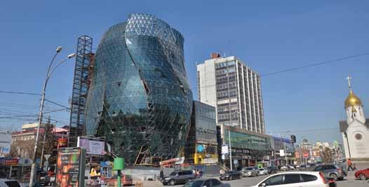
Figure 1: Flower bud.
highlighting the out-of-theordinary within the realm of structural engineering
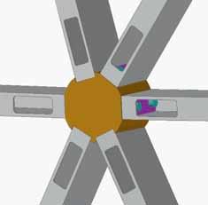
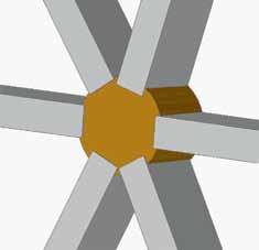
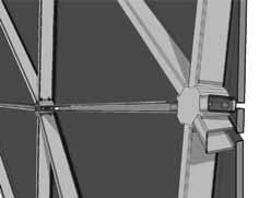
Figure 2: Node connections as viewed from the outside and inside. A nine-story glass building, shaped like a flower bud, is being built in the young scientific and industrial center of Siberia, Novosibirsk (Figure 1). In such a harsh weather environment – where during five cold days in January the Space Structures Reach Siberia temperature can drop down to -39 degrees (C), and the difference between the day and night By Denis Gerasimov temperatures in March can reach 30 degrees (C) (from -15degrees to +15 degrees (C)) – such a building may seem to be very risky and unexpected. Nevertheless, the designers deliberately chose the natural and transparent shape of a flower bud to challenge and confront the Siberian winter. This structure is directly connected to an existing rectangular building, creating a significant contrast with the unopened petals. The foundation and framework are built from reinforced concrete. The facade is fully captured by a cylindrical node system, a single-layer structure in the triangular geometry of the surface. Supporting Denis Gerasimov is the founder elements are directly connected to the structure. The of SPACESTRUCTURE in nodes are shaped aluminum tubes, and regions for Novosibirsk, Russia. He can be rod assemblies are milled on the cylindrical nodes reached at 2147409@ngs.ru, or (Figure 2). The configuration of the node is defined visit http://spacestructure.ru. by three parameters (Figure 3, page 24): • the angle between the tangent plane and the surface (α); • the angle of rotation (β); and • the screw angle for the desired edge (γ). The windows are heat strengthened glass units with both panes made of laminated glass. The most important point of the design was not to play too much with biological form associations, and to prevent naturalization so that people will get only a hint of the floral form. To emphasize the shape of the bud, the designers focused on the faces of the petals, which were difficult to design, calculate and make landfall with a negative angle. An additional challenge was relating the curvilinear outlines of the concrete-iron overlaps with the curvature of the shells. continued on next page
Figure 3: Angular parameters of each node element.
Another important decision was how to combine the elements of the shell; i.e., whether to use welding or bolting. The designers chose bolted connections, because visually they are more clear and linear. The main difficulty encountered during the project installation was not having a proper construction site, which hindered mechanization and made it impractical to mount large assembled elements. As a result, installers had to work with climbing equipment, using winches and hoists (Figure 4). Initially there was a permit for a threestory building, which was almost completely designed and built. During its construction, a ten-story building permit was obtained. Needless to say, it was difficult to adjust the project accordingly, strengthening the foundation and columns and maintaining the architectural idea without dismantling the erected frame. Planning and coordination of the project took place within the existing Russian framework of procedures and standards for design and construction. Some of the difficulties were associated with gaining approval from various government departments. The main concern was structural and fire safety. Designing the reinforced concrete frame in SCAD software (Figure 5), which is used a lot in Russia, helped the team to avoid questions and comments on that aspect of the project. On the other hand, the space frame facade represents a completely new product and therefore needed special tests for durability and fire resistance. Structure CAD (SCAD) is a computer program for structural analysis that uses the finite element method to determine the stress-strain state of the structure under static and dynamic effects, and also performs certain aspects of the design of structural elements. The software is based on a system of complex functional units connected by a single information environment. The project is created by verbally describing the design scheme in the input language. The import process then converts this representation into the internal format, which can also be converted back into text. The geometry of the design model can be formed with the help of AutoCAD. ANSYS is another computer tool for solving engineering problems and carrying out the calculation process (CAE-tools). This software was designed to optimize the
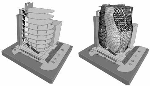
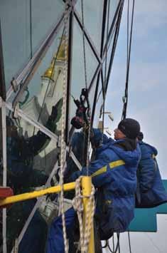
Figure 4: Installing elements by working with climbing equipment.
development of the early stages of design, reduce the cost of production and the development cycle of new products, and minimize the number of field tests. It performs simulation using the finite element method and facilitates solving all kinds of problems from various areas of physics, including structural, thermal, hydrodynamic, and electromagnetic mechanics, as well as combinations thereof. Finally, ADVANCE STEEL provides parametric three-dimensional modeling of steel structures and provides tasks for a 5-axis CNC machine to manufacture components. It is a powerful, easy-to-use tool based on Building Information Modeling (BIM) technology. The program automates the entire process of creating working drawings, specification sheets according to Government Standards, and CNC data. This improved the quality of the drawings, reducing the risk of errors. The main lessons from the design and construction of the flower bud will be learned later, after the building has been operating for some time, and will be linked to the climatic conditions of Siberia – not just winter’s cold, but also summer’s heat. However, from one standpoint, the experiment is already a success: the entire process used only local labor, without the involvement of outside contractors, and its features and overall aesthetic are promising to serve as a new beginning in the architecture of the Siberian city.▪
A Worthy Wager
Innovation at Federal Center South
By Jim O. Swenson, P.E., S.E. and Jason Black, P.E., S.E.
Th e Commons. Courtesy of Benjamin Benschneider.
Federal Center South Building 1202 is a state-of-the-art, high performance offi ce space for the Seattle District Headquarters of the United States Army Corps of Engineers (USACE). KPFF Consulting Engineers provided both civil and structural engineering services, from the design competition phase through to completion of this showcase High Performance Green Building project. Top among the many innovative design features that the project boasts is perhaps the largest use of a composite concrete and timber fl oor system in the United States. Composite concrete and wood fl oors were not part of the original design concept but ultimately became critical to achieving the project goals. Th is is that story.
Design-Build Competition
In 2009, the General Services Administration (GSA) solicited designbuild proposals for a high performance offi ce building for the USACE at the Federal Center South campus along the Duwamish Waterway in Seattle, Washington. Led by Sellen Construction and ZGF Architects, LLP, the team won the design-build competition in March 2010. Integral to the winning design was the concept of reclaiming heavy timber framing from the existing 1940’s warehouse on the proposed building site, and incorporating it into a signifi cant portion of the new facility.
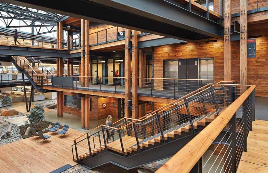
The Commons
One of the more striking spaces in the building is the centrally located atrium, or the “Commons,” which includes a gathering place, conference rooms and shared facilities. Th e design called for a beautifully fi nished, exposed, concrete fl oor that could also be used to encapsulate and hide some building system elements such as conduit. A concrete fl oor also had the advantage of being highly durable and low maintenance, and could be used as a structural diaphragm to transmit lateral forces to concrete shear walls. Th ere was also a strong desire that the structure of the Commons feature the salvaged timber. Th e fi nal architectural/structural fl oor solution in the Commons consisted of 4 inches of concrete over salvaged 2x6 timber decking supported by 8x16 wood beams spanning an average of 22 feet. Th is framing system was accepted by the GSA and was the basis for the pricing submitted by the design-build team.
Discovery after Deconstruction
After deconstruction of the existing warehouse, a comprehensive timber inventory was developed by the GR Plume Company, the
5' WIDE TEST ASSEMBLY 4" REINFORCED CONCRETE SLAB
TEMPORARY SUPPORT, TO ALLOW CONC PLACEMENT CUSTOM LAG BOLT
8" x 16" RECLAIMED BEAM 2x RECLAIMED TIMBER DECKING
Beam #3 test just prior to failure. Deconstruction of the warehouse. Courtesy of Charles Lozner.
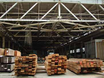
timber fabricator. This led to the unfortunate discovery that not enough salvaged timber was recovered to completely frame the Commons if the beams were spaced at 4 feet on-center, the calculated spacing using the National Design Specification for Wood (NDS) for conventional non-composite timber beams. A creative solution was required to save the design concept.
Defining a Solution
KPFF proposed completing the Commons using only the reclaimed timber from the old warehouse by increasing the beam spacing to 5 feet oc. and using composite construction. This innovative approach eliminated the need for non-salvaged timber and retained the character desired by the architect. This was important because the intent was to expose all the framing and it would be difficult to match the aesthetic of the on-site salvaged timber with new wood pieces. Although unproven, the team believed that using composite beams was a gamble worth taking, and one that seemed achievable within the schedule and budget. The GSA and USACE were approached about the idea, with the caveat that they would be able to review and approve both the design and testing procedures. Approval was obtained to proceed.
Design
While allowed by the current Uniform Building Code, a specific design methodology is not provided for composite concrete-timber beams by the National Design Specification® (NDS®), ACI 318, or 2009 International Building Code (IBC). This meant that testing would be required as an undefined system per IBC 1604.7. Interestingly, the Eurocode has a method for designing composite concrete-timber elements. In fact, several techniques for achieving composite action are used in Europe, often driven by a need to retrofit very old timber buildings. KPFF’s approach for achieving composite action was to use lag screws as the connectors between the wood and the concrete. To control the number of lag screws required on each timber beam, lag screws were custom fabricated that contained a longer section of un-threaded bolt length than a standard lag. This custom lag led to an innovative fabrication method by the GR Plume Company, which developed a drill bit that drilled two different hole diameters with a single plunge; a smaller one for the threaded portion and a larger one for the smooth shank. This streamlined the amount of labor required to drill all the lag screw holes and install the lags. Now all that was needed was to put the assembly to the test.
Test Procedure
The team initially chose 3 full-size, representative beams from the salvaged timber for full scale testing. It was acknowledged that 3 samples would not necessarily represent a significant statistical data set, and that the result of each test sample would ultimately have to be taken on its own merits. Then a decision would have to be made as to whether to proceed with construction using composite beams. KPFF developed a test procedure in accordance with IBC section 1715. The procedure addressed the physical test setup, the load increments (concrete eco-blocks), the order and location of how the load increments would be applied, what kind of data would be collected, how the beams would be instrumented, and what the criteria for success and failure would be. It was also critical that all aspects of the test assemblies replicate the eventual in-place construction as close as reasonably possible. The onsite testing was conducted in an area of the warehouse that had previously been used for heavy manufacturing. KPFF performed finite element modeling to evaluate the existing slab and foundations below where the testing would occur. The analysis demonstrated that the testing would not be affected by deflections of the existing floor and foundation system. Another issue was how to pour the concrete slabs for each test beam. The actual building construction would involve single span wood decking spanning between the beams. In order to produce a flat surface for the bottom form of the concrete, but still ensure a direct connection between the slab and the beams, small notches were cut into the top of the beams to create seats for deck bearing. This kept the top of decking relatively flush with the top of the beams and allowed direct contact between the slab and the beams. Since the test slabs would need to include only half of a span on each side of a beam, the edges of the concrete were supported by short “pony walls”. It was critical to repeatedly cut down these walls to shorten them after the initial concrete set to ensure they were not shoring up the composite slabs during the curing process. These walls remained as a safety measure during test loading. continued on next page
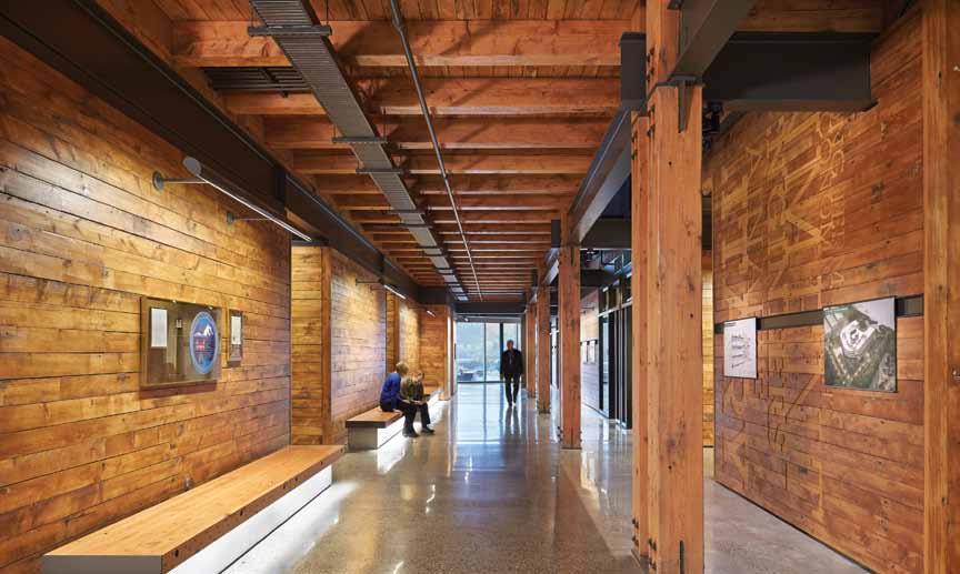
Commons interior. Composite floor above. Courtesy of Benjamin Benschneider.
Initial Beam Testing
Before installing the decking, lag screws, reinforcement, and slabs, it was decided to try and obtain modulus of elasticity (E) values for the bare beams. A test was performed to load a beam with a single load increment, measure the deflection and back-calculate a value of E. Additionally, vibration testing was performed to establish the natural frequency and back-calculate an E value using the vibration response. This testing indicated an average E of 2,500 ksi, compared to the NDS design value of 1,600 ksi. Taking the time to establish this true value of E would prove to be a very useful decision. After the composite test beams were constructed, the slabs were allowed to cure for 28 to 30 days, with 12 to 14 deflection measurements taken to evaluate creep over the cure time. The amount of measured creep for the 3 beams ranged from about 3/16 to ¼ inch, showing very little spread between them. Sellen constructed the test beams, support frames, and loaded the beams during testing. KPFF instrumented the beams and took measurements during the tests. GSA and USACE were kept aware of the testing process and were invited to attend.
Final Testing
With the test specimens cured and in place, it was time to try to break things! The test process required that each composite beam hold twice the design live load (2x80 psf) for 24 hours and then be able to recover 75% of the measured deflection within 24 hours of being unloaded. The first beam passed this test with flying colors, as did the other two. In fact, one beam recovered 91% of its measured deflection from this portion of the test. None of the three exhibited any physical signs of distress from this initial loading phase.
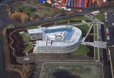
Aerial of completed project.
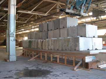
After conducting the required test for twice the live load on each specimen, each beam was tested with the intent of failing it. For beam #1, concrete eco-blocks (weighing 1750 pounds each) were placed until the beam was carrying 38,500 pounds of blocks, or more than 400% of the design live load. This was unexpected. Additionally, there were no visible signs of distress at that point. It was decided to stop at that load and let it sit fully loaded for 24 hours. No visible signs of distress were observed after 24 hours. For beam #2, concrete blocks were stacked on the assembly until 56,000 pounds of load was present, more than 600% of the design live load. At this point there were safety concerns because the entire slab-beam “T” section was beginning to rotate; loading was stopped in order to avoid the whole assembly toppling over. No visible signs of failure or distress were observed then, or after the blocks were removed. The deflection gages had maxed out with a value of 1.285 inches at around 550% of design live load. Due to the experiences with beams #1 and #2, the loading procedure for beam #3 was altered to use larger eco-blocks for the initial loading course to allow more weight to be stacked with a lower center of gravity. At just over 500% of the design live load, a small crack was
detected around a knot at about a third point in the beam span. At about 650% of design live load, the crack lengthened and a series of cracking sounds were heard. Finally, at 61,250 pounds of load, it was decided that it wasn’t safe to load the beam any further. About 10 minutes after this last load increment was placed, the wood beam failed in flexure with a sudden, loud crack!
Composite Action
All three of the test specimens supported significantly more than the required load with no signs of distress. There was no question that the system had adequate capacity, but how much composite action was achieved? After analyzing the deflection results, it was estimated that the amount of composite action achieved probably ranges from 60% to 80%, depending the value of “E” used in the calculation. It is likely closer to the lower end of this range, which is consistent with results from testing in Europe for systems with lag screws. If higher composite action is required, then a different technique should be used to develop the composite action. In our case, it was enough.
Building Data:
Size: Three-story, 209,000 SF building Reclaimed heavy timber and decking in Commons: 300,000 BF Targeting LEED Gold
Team:
Owner: General Services Administration (GSA) Tenant: United States Army Corps of Engineers (USACE) Seattle District Structural & Civil Engineer: KPFF Consulting Engineers Contractor: Sellen Construction Timber Fabricator: GR Plume Architect: ZGF Architects, LLP
Funding:
American Recovery and Reinvestment Act (ARRA)
Summary
Federal Center South Building 1202 is a definitive statement that visionary architecture, innovative engineering and design/build delivery methods can produce world class architecture worthy of celebration. Creative problem solving, a willingness to take risks, and a high degree of trust within the design build team all combined to allow the delivery of a world class facility with a truly innovative concrete and timber composite floor system.▪ Jim O. Swenson, P.E., S.E., is an Associate and project manager with KPFF Consulting Engineers. He was the lead engineer for the design and testing of the composite beam system used on Federal Center South 1202. Jim can be reached at JimS@kpff.com. Jason P. Black, P.E., S.E., is a Structural Principal with KPFF Seattle. Jason can be reached at Jason.Black@kpff.com.
ADVERTISEMENT - For Advertiser Information, visit www.STRUCTUREmag.org

SFPUC Headquarters Building
An Innovative High Performance Structure
By Leo Panian, S.E. and Nick Bucci, S.E.
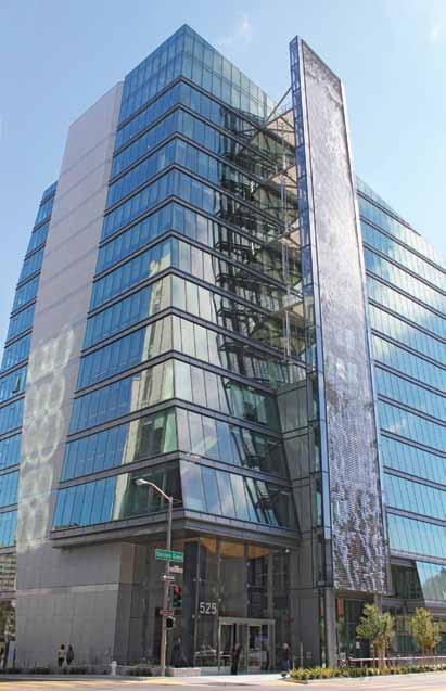
The San Francisco Public Utilities Commission’s (SFPUC) new headquarters in San Francisco, California, set a new standard for high-performance structures when it opened in June 2012. The building, slated for LEED Platinum certification, is a showcase for a host of leading-edge sustainable design elements, making it one of the greenest office buildings in the nation. In this case, the design of the structural system, including its post-tensioned concrete shear walls and construction materials, made key contributions in achieving this distinction. The structural design followed a simple strategy of creating a highly durable and resilient structure that could be built with significantly reduced environmental impact, for a cost that was comparable to a more conventional design. In seismic country, the key to durability and resilience is designing a structure that is able to withstand a major earthquake with minimal damage. As a provider of lifeline infrastructure, the SFPUC was keen to ensure that the new facility could be easily repaired and reoccupied immediately after a large earthquake. This meant designing to a higher standard of seismic performance, which would limit structural deformations during a major shock and allowing the building to return to its original plumb position, protecting the building, occupants, contents and its systems. An innovative approach using post-tensioned concrete shear walls with composite link beams was applied to cost effectively satisfy the ambitious seismic criteria. The high-performance seismic design of the SFPUC was based on a two-tiered criteria, which required that the structure would meet 1.0% maximum interstory drift under the design basis earthquake (DBE), corresponding to a return period of 475 years, and 1.5% maximum drift under the maximum considered earthquake (MCE), corresponding to a 2,500-year return period. Moreover, the structural system has the ability to recenter the building, resulting in negligible residual deformations. In comparison, a similar building designed to conventional standards would be allowed a maximum drift of 2.0% under the DBE, with no limit on residual drift. Major non-structural components, including the exterior cladding and the mechanical, electrical, and plumbing equipment of the building were designed to
Figure 1: Completed SFPUC building.
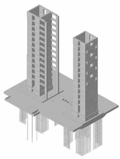
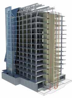
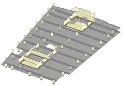
Figure 2: Schematic view of underside of floor framing and core walls. Figure 3: Isometric view of core walls. Figure 4: Schematic cutaway view of the structural system.
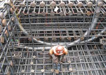
Figure 5: Mat foundation reinforcing with curved saddle for post-tensioning of the vertical post-tensioning cables.
remain substantially free from damage during the DBE event. The exterior cladding system was explicitly designed to remain damage-free at the DBE event and operable with limited damage at the MCE event. The thirteen-story structure extends almost 200 feet above grade and comprises roughly 277,500 square feet (Figure 1). The structural system consists of a framing system of post-tensioned concrete slabs and beams supported on concrete columns and concrete core walls. The core walls, located at each end of the building, provide the building’s lateral resistance (Figure 2 ). The floor plan consists of an asymmetrical column-grid arrangement with long spans (nearly 41 feet) in the transverse direction of the building and short spans (20 feet) in the longitudinal direction (Figure 2). With this arrangement, a flat-plate slab solution would be impractical and inefficient. The structural engineers devised an efficient framing solution consisting of shallow transverse post-tensioned beams and one-way longitudinal post-tensioned slabs. The beams are typically 36 inches wide and 16 inches deep, and the slabs 6 inches thick. The two concrete core shear walls are founded on a 10-foot-thick mat foundation atop micropiles embedded 65 feet below. This combination of mat foundation and micropiles are intended to resist the seismic overturning load (Figure 3). The micropiles are approximately 10 inches in overall diameter and consist of a continuous 2.5-inch diameter high-strength threaded rod that is inserted into the drilled shaft and then pressure grouted, creating piles capable of achieving high tension and compression strengths. While micropiles have traditionally been used in retrofit and transportation applications, there are several advantages to using micropiles for new construction. Their small diameter allows for a higher concentration of strength and stiffness per area, and the piles can be field tested, which allows for a more efficient design. For seismic resistance, the building uses an innovative system of self-centering concrete core shear walls and composite link beams (Figure 4). The shear wall design consists of conventional bonded reinforcing and vertical unbonded post-tensioning (PT) cables. At each core wall, the vertical post-tensioning tendons extend from the top of the core wall down through a saddle within the mat foundation (Figure 5) and back up to the top of the wall. Each of the two core walls contains eight tendon bundles that are about 400 feet long. Each bundle comprises up to 28 continuous 0.6-inch diameter strands. The vertical post-tensioning helps to provide the strength and elasticity needed to recenter the structure. Additionally, the vertical post-tensioning tendons allow for a reduction of approximately 50% in the quantity of the vertical bonded mild-steel reinforcing in the walls. This reduces labor costs and minimizes wall congestion. The cables are post-installed through corrugated steel ducts that are installed in the walls (Figure 6 ) and stressed at the top of the structure with a hydraulic jack (Figure 7 ). During a seismic event, the mild-steel reinforcing bars yield to dissipate energy, much like the behavior of a conventional concrete shear wall. However, the unbonded tendons remain elastic to provide a positive restoring force that recenters the structure. The walls are proportioned so that the overall flexural strength attributable to post-tensioning alone is approximately 50% of the total flexural strength of the wall. It is critical that the walls are detailed to maintain sufficient ductility and good hysteretic behavior under the high compressive strains and repeated load reversals. This is even more important for a PT shear wall, where the PT imposes additional compressive force on the wall. In order to ensure adequate compressive strength at the wall boundary zones, the walls were constructed of high strength concrete designed to reach a compressive strength of
Figure 7: Hydraulic stressing jack being placed over the vertical posttensioning tendons.
SOILSTRUCTURE.COM
Substructural Software
1. Soldier Pile/Wood Lagging 2. Multi-Level Tieback Walls 3. Laterally Loaded Drilled Pier 4. Anchored or Cant. Sheetpile 5. Cantilever Retaining Wall
Only $280 to $450. Nothing to ship.
Same Day Email Activation
Free Downloads at: http://www.SoilStructure.com
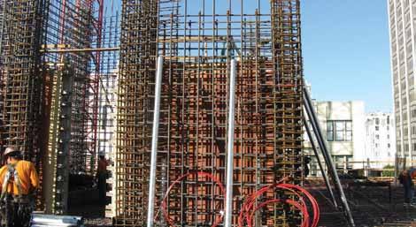
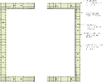
Figure 8: Typical shear-wall cross section.
8,000 psi at 90 days. Additionally, special care was taken while detailing the boundary zones by adding extra confining reinforcing to extend the strain capacity of the concrete at ultimate loading. Nonlinear response history analysis was used to predict forces in critical elements, eliminate non-ductile failure modes, and ensure stable flexural mechanisms. The walls are heavily reinforced at the plastic hinge zone and first several levels of the structure. A typical wall cross section at the plastic hinge zone is shown in Figure 8. The wall consists of #10 vertical bars at both the boundary areas and at the distributed field reinforcing, with #9 horizontal shear reinforcing. At the boundary zones and areas of high compression force, the walls are confined with #5 cross ties and stirrups. In order to expedite onsite construction speed, the boundary reinforcing cages were preassembled with the stirrups installed. The horizontal reinforcing bars were lapped outside of the boundary zone to allow for easier field installation and T-heads were used to limit the congestion. The composite link beams are another innovation incorporated into the structural design (Figure 9). The core walls enclose some of the building’s elevators, stairs, and mechanical shaft. The door openings into the core create coupling beams formed over the doorways. Traditionally, coupling beams are heavily reinforced, often with diagonal reinforcing, which makes them difficult to construct. For this building, the composite coupling beams were formed with a 3/8-inch thick steel jacket that was designed as both a stay-in-place formwork and beam reinforcing. The link beams are 30 inches wide and vary from 20 to 36 inches deep (Figure 10). The external steel jacket alters the behavior of the link beam in a fundamental way. Under cyclical seismic loading, the steel jacket forces a single flexural crack to form at the face of the wall, rather than allowing the distributed cracking that would be expected in a plastic hinge region of a conventional beam. Furthermore, the steel jacket relieves the compressive strains on the concrete and allows for a more ductile response with less degradation in strength and stiffness. These effects required several specialized design considerations. The longitudinal reinforcing bars in the link beams were debonded from the surrounding concrete with waxed sleeves at the joint between the steel jacket and the concrete core wall to allow an adequate plastic strain length, to prevent premature tensile fracture. In addition, embedded steel brackets were provided to mechanically restrain the link beam, ensuring a direct, reliable transfer of shear at the interface with the walls. The external steel jacket eliminates the cracking and spalling damage that would otherwise be expected with a conventional coupling beam, thus minimizing the need for extensive post-earthquake repairs.
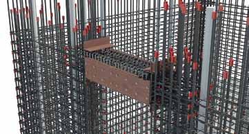
Figure 9: Rendering of the composite link beam and shear-wall reinforcing.
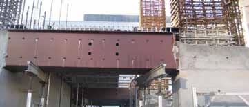
Figure 10: Link beam steel jacket.
As the SFPUC was designed to achieve LEED platinum status, it was important for the team to address the environmental impact of the concrete. Through a collaborative partnership between Tipping Mar, the general contractor, and the concrete supplier, custom low-cement concrete mixtures were developed that were shown to reduce the carbon footprint of the material by 50% overall. The high-strength green-concrete mixes were tailored for each application, and specified the replacement of Portland cement by up to 70% using a combination of slag and flyash. The SFPUC headquarters project embodies the spirit of the institution it serves. It represents a significant advancement in how office buildings are designed and built. In this spirit, Integrated Project Delivery (IPD) was selected for the design and construction of the building. This delivery method allows for a collaborative relationship between the owner/ developer (SFPUC and SF DPW), the contractor, and designers, whereby the risks and rewards are shared. This building’s design and construction is a demonstration and guiding example of how leading-edge technologies and innovations can come together to fulfill an ambitious civic vision of sustainability.▪
The building was designed through the collaboration of KMD Architects and Stevens and Associates Architects, with Tipping Mar and SOHA Engineers performing the structural engineering design. Webcor Builders was the general contractor and Central Concrete was the concrete supplier for the project. San Francisco’s Department of Public Works was responsible for managing the project.
Leo Panian, S.E., is a principal at Tipping Mar, Berkeley, California, and served as associate-in-charge on the SFPUC headquarters project. Leo may be reached at Leo.Panian@tippingmar.com. Nick Bucci, S.E., is a project manager at Tipping Mar and served as project manager on the SFPUC headquarters project. Nick may be reached at Nick.Bucci@tippingmar.com.
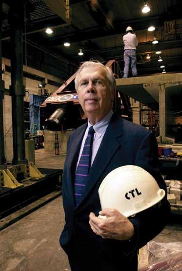
W. Gene Corley
The Structural Engineering Community Mourns the Loss of an Innovative Leader
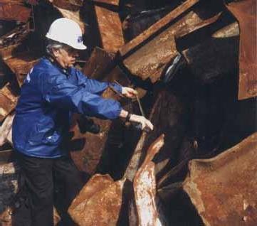
On March 1st, the structural engineering community was saddened by the news of the passing of Dr. Gene Corley after a brief battle with cancer. At age 77, Dr. Corley had accomplished much in his career, but was most notably known for his investigation of the collapse of the World Trade Center towers after the terrorist attack on September 11, 2001. A recognized industry leader, Gene was at the forefront of the structural engineering profession, and the development of building codes and standards. W. Gene Corley was born in in 1935, the son of the late Clarence W. and Mary Douthit Corley of Shelbyville, Illinois. Gene was influenced from a young age by his father, a contractor who built single-family homes, shopping malls and grocery stores. In an interview with Dr. Corley by the Chicago Tribune in 2001, Gene mentioned that “I was on building sites even before I was big enough to crawl.” He graduated from Shelbyville High School in 1954 and went to study architecture, but didn’t think he could draw well enough. An early indicator of his dedication to the field of structural engineering was his commitment to his education, receiving a Bachelor of Science Degree in Civil Engineering (1958), and a Masters (1960) and Doctorate in Structural Engineering (1961), all from the University of Illinois. Upon completion of his Ph.D., he served as a commissioned officer in the U.S. Army. During this period, Dr. Corley was a research and development coordinator with the U.S. Army Corps of Engineers at Fort Belvoir, Virginia. His duties included bridge design, acceptance testing of mobile floating assault bridge equipment, design of tank launched bridges and fatigue testing of bridges fabricated from high strength steel, aircraft aluminum and titanium alloys. In the 1960s, Gene turned down a job with NASA working on the lunar rover program, and took a position at the Portland Cement Association (PCA), a nonprofit that represents cement companies. According to Gene, “After I finished my Ph.D at the University of Illinois, I spent three years in the military. At the end of that, I interviewed all over the state. I had some fantastic opportunities at that time. It was a really good time for engineers to look for work. I actually had offers for more money to do other things, but I felt that the offer from the Portland Cement Association was exactly in line with what I’d been trained to do, and was my best opportunity...” As demand for consulting grew, the research and development laboratory for PCA was eventually spun off as a for-profit company, expanding into other building materials and engineering issues and offering engineering, testing, and consulting services. First known as Construction Technology Laboratories, the firm changed its name to CTLGroup in 2005 to reflect the fact that it provided both laboratory services and engineering consulting services. When CTLGroup first became an independent subsidiary, it expanded its scope of services beyond concrete and modified its structures laboratory to incorporate the testing of steel structures. While serving in successively more responsible positions, Dr. Corley was directly involved in the development of improved design procedures for structural concrete, concrete pavement, railroads and structures subjected to fire loads. In addition, he served on earthquake
From Chicago Tribune, March 6, 2013 © 2013 Chicago Tribune. All rights reserved.
damage investigation teams, carried out investigations of damaged or deteriorated structures and developed repair procedures for numerous buildings and bridges. Gene served as an expert advisor during the investigation and trial resulting from the 1993 fatal fire at the Branch Davidian complex in Waco, Texas. In 1995, Dr. Corley led the investigation of the structural performance of the Alfred P. Murrah Federal Building in Oklahoma City, following the bombing there. He served as the head of the Building Performance Assessment Team (BPAT) which involved the American Society of Civil Engineers, as well as representatives from the Federal Emergency Management Agency (FEMA), the United States Army Corps of Engineers, the General Services Administration, and the National Institute of Standards and Technology. Commenting on how his career evolved, Gene highlighted the emergence of “forensic” engineering. “…there definitely have been big changes. One of the changes is that at the time I was hired as a development engineer for the PCA laboratories, the science of construction forensic work really didn’t exist. There were very few people doing anything like that at the time. When I started with PCA, I was doing work to develop new design concepts and better ways to use concrete. Really most of my work dealt with ways to develop more economical and safer high-rise buildings. That’s what I started doing. Then, as I progressed in my experience, I was put in charge of all engineering uses of concrete … as time went along, I started getting hired as a consultant on jobs where people either wanted to
do things that were unusual -that hadn’t been done before -or they had tried to do something and had run into trouble and needed help in finding a solution to the problem. That led into the investigation of more and more troubled structures and eventually into the investigation of collapses -finally, of major collapses and major problems with structures of all types.” Dr. Corley built his reputation as one of the world’s experts on structures damaged by natural and manmade disasters as he investigated some of the most notable building failures in recent U.S. history, earning him the label of the “preeminent expert on building collapse investigations and building codes” by the American Society of Civil Engineers (ASCE). As the nation and the world watched coverage of the September 11, 2001 attack on the World Trade Center’s (WTC) twin towers, the following fires, and the eventual collapse of the World Trade Center Towers, the engineering community immediately began to ask questions: How were the towers able to withstand the enormous impact of a 767 without collapsing? Could anything be done to make the buildings survive longer in the ensuing fires? To help answer these questions, the American Society of Civil Engineers/Structural Engineering Institute and FEMA joined together to study the performance of collapsed and damaged buildings, and asked Dr. Corley to lead the team. With the cooperation of nearly a dozen other societies and organizations, this team of 23 Structural and Fire Protection Engineers completed their work on May 1, 2002. Gene would describe the methodologies and findings of the WTC investigation in later interviews. “There are usually two parts to any investigation like that. The early investigation needs to be done rapidly and with whatever resources are available at that point, and from that first investigation, recommendations can be made for, in some cases, further investigations, and for whatever can be done differently, such as changes in building codes… we had to find out what happened at the WTC, to preserve evidence of what had happened, and to recommend what additional work, if any, needed to be done.” “We found one piece of steel across the street from Tower 1 and by reading the numbers on it, we could identify that it was from the area above where the aircraft went in, and where there was fire in Tower 1. The building it was imbedded in had no fire in it. By looking at the piece of steel, we could see that on one end, it showed no indication of fire, and that end was in a position low enough to be below the fire, but the other end was smoke-coated and had fire damage. This showed something very important, and that was that at the time it was in the fire there was no fireproofing on that piece of steel. That was important in bringing us to the conclusion which the National Institute of Standards and Technology (NIST) came to also, i.e., that when the planes hit the buildings, they knocked off fire proofing from the steel and that left the steel more vulnerable to fire after impact.” W. Gene Corley authored hundreds of technical papers and books, and frequently lectured on the subjects of prevention of failures, effects of earthquakes and design and repair of structures. Dr. Corley was passionate about codes and standards that affect structures, and chaired ACI Committee 318 for six years as the committee developed the 1995 Building Code Requirements for Structural Concrete. He also served on several other national and international committees that prepared recommendations for structural design and for design of earthquake resistant buildings and bridges. His professional activities resulted in his receiving numerous national and regional awards. Dr. Corley served in leadership roles for several professional organizations, both national and international, including the National Council of Structural Engineers Associations (NCSEA), the Structural Engineers Association of Illinois (SEAOI), the Illinois Structural Engineering Board (ISEB), the National Council of Examiners for Engineering and Surveying (NCEES), and the ASCE/SEI Technical Council on Forensic Engineering. Notably, Gene was instrumental in the formation of NCSEA. As a past president and leader of SEAOI, he, along with Jim Cagley, Paul Fratessa (deceased), and a few others, founded NCSEA in 1993. Gene served on the first Board of Directors and was the fourth NCSEA President, from 1996-1997. During his presidency, the organization recapitalized, moved its offices, and hired a new executive director. Gene loaned his talents and prestige to the upstart organization and was instrumental in its success. He was passionate regarding the role of structural engineers in the protection of the public. Dr. Corley also strongly supported licensing of structural engineers. “The structural engineer is the only one always responsible for life safety,’’ said Corley. “To provide life safety takes a level of knowledge in structural engineering. It is not enough to know civil engineering.” “Gene’s legacy in the structural engineering profession is unparalleled. He was an innovative thought leader who consistently contributed generous amounts of his time and knowledge to the profession,” said Jeffrey L. Garrett, Ph.D., S.E., CTLGroup President & CEO. Dr. Corley’s interest in the structural engineering profession was demonstrated daily by his tireless efforts in helping state structural engineering associations, giving technical presentations and seminars, and teaching examination review courses. He didn’t leave a list of monumental structures for the world to remember him by; and there are no bridges or high rise buildings associated with his name. Gene left something much more significant. He left a legacy of service to the profession of structural engineering, along with a reputation of integrity, astounding knowledge, and class. Gene Corley is survived by his wife of 53 years, Lynd, three children (Anne, Bob, and Scott) and nine grandchildren. Please join NCSEA, SEI, CASE and STRUCTURE magazine in sending condolences to Dr. Corley’s family.▪
Quotes attributed to Dr. Corley were taken from an interview conducted by Laurence W. Johnson of the Skokie Public Library in 2011, transcripts of numerous committee meetings, and general comments recorded in the press.


