26 minute read
PRACTICAL SOLUTIONS
solutions for the practicing structural engineer
In the design of concrete structures, where concrete slabs and walls are used as the environmental barrier, water leakage is a concern. In well consolidated, normal weight concrete, high pH components within the cement/gel paste react with iron on the steel surface and resist corrosion from actively occurring around the steel. This is called “passivation.” However, concrete cracking, due to high stress and associated strain defects in the element, allows leakage and lateral migration of water, and effectively introduces all of the necessary components – oxygen, water, and an electrolyte – needed for uncontrolled corrosion of the steel reinforcement. Groundwater leakage through concrete continues to bring water with dissolved oxygen and enhances the electrolytic environment, and salt water exacerbates the problem dramatically. To help control leakage into a concrete element, it is important to understand the best water control solution is generally to provide a new, exterior membrane to a structure. However, initial cost, accessibilSolving Interior Water Leakage Problems ity, public nuisance, or other circumstances, may dictate that such a solution is prohibitive. Below-Grade In such cases, other methods of water control must be explored. When solving a water leakage problem around a building Five Classic Approaches foundation or civil structure (tunnels, tanks, vaults, pipes, bridges and docks), approaches can By Brent Anderson, P.E. be applied either exterior (positive side) or interior (negative side). Positive side solutions are in direct contact with hydrostatic water, and therefore resist water penetration at the interface. Negative side solutions are not in direct contact with water. It is common to use a combination of solutions, or perhaps different solutions on various parts of a Brent Anderson is the Moisture Control Solutions Team Leader at Structural Technologies. He serves on ACI 332 Residential Concrete and previously served on ACI 515 Protective Coatings for Concrete. Brent can be reached at banderson@structuraltec.com. structure, to control water migration. After a leakage problem has been diagnosed, five classic approaches to an acceptable resolution can be explored: 1) Crack/Joint Routing, Caulking, and/or Dry-packing 2) Crack/Joint Injection, Chemical Grouting 3) Water Management & Drainage 4) Coatings, Sealers, Reactants, Sheet Liners 5) Electro-Osmotic Pulse (EOP) Technology There is not always one right answer to the problem and there are exceptions to any water control solution, so blended approaches are very common.
Crack/Joint Routing, Caulking, and/or Dry-packing
A simplistic, first attempt is to paste over a leaking crack/joint with a high viscosity compound. This paste should extend over the crack/joint one inch and the paste should be 1/8-inch thick; sometimes it is reinforced. On rare occasions, this may temporarily resolve the leakage problem in the long term, provided cracks are static. Costs vary; $5.00 per linear foot is common, plus mobilization. A slightly more robust solution would be to grindout or rout-out the crack in a “U” or “V” shape, and fill with a high viscosity, low modulus filler. The performance of this solution depends upon slot depth and width, use of bond breaker, and adhesion to concrete sides. Slots ranging from 3/8 x 3/8 inches, to ¾ x ¾ inches, are common. Fillers ranging from elastomeric (low modulus) sealants, to high modulus epoxies are used. Costs vary, $25.00 per linear foot is common, plus mobilization. Similar to using polymeric compounds in sawcut or routed-out concrete slots, it is possible to fill the slot with a Portland cement based compound/mortar. The most common technique is to use a crystalline growth mortar. Similar to using high modulus epoxy fillers, the crack needs to be relatively static. Routing out slots in concrete for crystalline mortar filling generally requires a 1- x 1-inch slot, up to 1.5 x 1.5 inches; larger slots are also common. Costs vary; $45.00 per linear foot is common, plus mobilization.
Crack/Joint Injection, Chemical Grouting
There are three basic approaches for sealing water leaks at concrete wall/floor defects (cracks and joints). These approaches are as follows: 1) Backside Injection (curtain grouting), whereby a grout material is deposited behind the wall/floor crack/joint or into the earth backfill (permeation grouting or soil solidification). The grout material solidifies soil and plugs leaking water points of origin. 2) Internal Injection (interception grouting), whereby a grout material is deposited into the internal concrete crack/joint at middepth. The internal injected grout fills the crack/joint from internal to external face. 3) Surface Mounted Injection, whereby a grout material is applied to the surface of the leaking crack/joint, or is partially routed and plugged with a water impedance material prior to pressure injection. Typical resinous injection and generic grout types available in the industry include: • Epoxies • Bentonites • Hydrophobic Urethanes • Hydrophilic Urethanes • Two-Component Structural Urethanes • Acrylamides • Acrylic Resins • Rubberized Mastic or Gels • Micro-Fine Portland Cement This injection process involves placement of a resinous polymer, and/or non-reactive gel or paste, into a crack zone or behind it. Most chemical grouting within the crack zone involves placement of a low viscosity, reactive, epoxy, urethane, or
acrylic-based polymer. These reactive polymers fill the cracked section and theoretically plug the void. They bond to the crack sidewalls in various degrees depending upon crack cleanliness. These various reactive polymers exhibit different degrees of elongation. The grout selection must consider crack width, movement, orientation, age, and sequence. The cost of injection grouting varies considerably based on mobilization and access, quantity of work, security requirements, time duration per shift, and material used. Rough cost ranges may be as follows: 1) Backside Injection (curtain grouting); variable cost range = $35.00 to $100.00 per square foot 2) Internal Injection (interception grouting); variable cost range = $75.00 to $485.00 per linear foot 3) Surface Mounted Injection; variable cost range = $20.00 to $70.00 per linear foot
Water Management and Drainage
This concept can be very simple to complex. Simple water management solutions may involve cutting a slot into a floor slab adjacent to leakage area(s) and channeling it to a nearby drain. Slot depths and widths vary based on water flow rates. Costs vary, but $25.00 per linear foot, plus mobilization, is common. A more comprehensive solution may involve cutting out a much wider and deeper slot into or under the floor slab (may include soil removal), adjacent to leakage areas, and installing perforated drain pipe or a manufactured drainage mechanism that collects water and channels it to a sump collection area. Costs vary from $25.00 to $100.00 per linear foot, plus mobilization. The next water management and drainage step up involves placement of a drainage media to move water from the leakage area to a collection point. Collected water is either pumped to the surface or drained. Water management materials usually consist of some type of deformed plastic sheeting attached to the wet substrate that collects, channels and deposits water to centralized locations. Concrete, masonry, or gypsum sheeting often cover these systems for aesthetics and fire protection. Costs vary from $75.00 to $400.00 per linear foot, plus mobilization.
Coatings, Sealers, Mortar Reactants
This process involves placement of a bonded layer, or chemically reactive mortar agent, on the concrete interior surface experiencing water leakage (negative side treatment). All coatings and reactive agents require the substrate to be free of permeating water prior to installation. Thus, chemical grouting may be first performed to alleviant active water leakage prior to coating or reactive mortar agent installation. Interior coatings generally come from the same generic family of polymers as used for pressure injection, i.e., epoxy, urethane, acrylics and/ or latex. Interior coatings must resist both the effects of negative side water and water-vapor pressure. These coatings can be “breathable” (vapor permeable) or “non-breathable” (vapor retarders). Interior coatings depend upon adhesion to the concrete substrate exceeding liquid and water vapor pressures. Further, they must be flexible to accommodate substrate movement. Costs vary from $5.00 to $20.00 per square foot, plus mobilization. Some coatings may be chemical reactive agents, commonly referred to as crystalline growth slurrys or mortar treatments. These are surface applied mortars with reactive chemistries to the concrete substrate, meaning that they react with cement hydration by-product(s). Calcium hydroxide is a high pH, soluble salt by-product, contained within the micro voids and pores of the concrete gel matrix. Surface-applied reactive treatments to a damp concrete substrate can be formulated to react with un-hydrated cement, free calcium oxide and calcium hydroxide, thus creating silicate based crystal growth in pore spaces and micro voids within the concrete gel matrix. These crystal growth by-products can plug micro voids and pores, and very fine cracks in the concrete matrix, thus creating a water resistant barrier. Costs vary from $4.00 to $12.00 per square foot, plus mobilization.
Electro-Osmotic Pulse (EOP) Technology
This technology is an electrical solution for drying out concrete and is capable of protecting reinforcing steel in concrete. EOP systems fundamentally consist of a power supply and two oppositely charged electrodes. The power supply charges an anode (+) terminal at one end of a concrete element and a cathode (-) terminal at the other end. Low voltage (24 to 28 volts) output from the power supply, across the terminals, is created through the concrete element via the water containing micro-voids. Current flows from cathode to anode and electrons flow from anode to cathode. EOP installations are designed to create low intensity electric field(s) within wet concrete element(s) and adjacent soil. Fundamentally, the design places oppositely charged electrodes on each side of a wet concrete element or area. If the concrete element and adjacent soil is conductive (wet), and the micro-voids are partially filled with water, ions can move from electrode terminal to electrode terminal because an electric field was created in the damp concrete between said terminals. Over time, water moves from anode to cathode and dries the concrete out. Wet concrete is more conductive than dry concrete, thus high internal moisture content concrete is more conductive than dry concrete. Lower strength concrete is usually more conductive as well. The highest electrical conductivity is at water leakage locations because the concrete micro-structure is close to saturation. EOP system design depends on many factors. Placement of anodes is either in a grid system or at wet locations where defects in the concrete element exist. Cathodes are spaced in a manner whereby the electric fields are relatively uniform across the concrete element. Because this is an electrical solution, the designer needs to ensure that outside electric field(s) will not interfere with the EOP system. The cost of EOP installations vary considerably, however a range of $400.00 to $1,200.00 per linear foot of wall length is common. Slabs may be in the range of $25.00 to $80.00 per square foot.
Conclusions
Facility owners tend to approach water leakage problems in a systematic way. They tend to explore solutions on a lowest-to-most-costly basis, coupled by spot location-focused to a broad-based scope repair. Engineers and contractors, with input from a facility owner, generally will take a similar approach. Consider further that each water control approach can use a vast array of products with material properties that seem similar; however, they can have quite different results. Be mindful that the contractor’s experience may be more important than the design approach selected. When engineers and consultants are involved with the water control process, they typically want to determine leakage root cause prior to design. A systematic engineering approach for identifying and solving moisture problems could be outlined as follows: 1) Gather history of problem, 2) Understand the design, 3) Search for the leak path, 4) Perform proper tests, 5) Discover the root cause, and 6) Determine solution approach. After the water leakage problem root cause is determined, the engineer/consultant and/or contractor must match a cost effective solution with the budgetary criteria that provides the longest service life. This requirement involves considerable experience and knowledge about the concrete structure, materials and tradesmen capabilities.▪
SAN MARCOS HIGH SCHOOL
San Marcos, California
By Hossain Ghaffari, Ph.D., P.E.
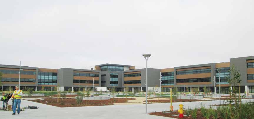
Classroom building and central quad area.
The $136 million 420,000-square-foot San Marcos High School opened in January 2014 in a phased reconstruction of the entire project site. This project transformed the existing 1,800 student capacity single-story complex to a 3,000 student capacity state of the art multi-story high school complex, more than doubling the size of the old school. This new facility provides equity with the other District high schools and includes College Prep and Career Technical Education spaces for the humanities, math/science, technology, performing arts, practical arts, agricultural sciences, and special education programs. The new San Marcos High School Campus features several separate structures that utilized tilt-up and cast-in-place concrete and structural steel construction, including: a 2-story Performing Art Center with a 400-seat theatre, a 2-story Athletic Center with a 3-court gym, a 3-story Academic Building, and a 1-story Academy Building. There are also additional one story structures housing the mechanical equipment, athletic fields shower and lockers and press boxes. Concrete played an important role in the project, serving as a durable and regional material that has recycled content when teamed with rebar and fly ash. Its thermal properties allow spaces to stay cooler during the day, further reducing loads on the campus’ mechanical systems. Therefore, for the buildings where concrete façade was used, it was an easy decision to use concrete shear walls as the lateral force resisting system for the structure and tilt-up construction was preferred based on two critical concepts. It was imperative that the finish of the exposed concrete surfaces was as flawless as possible, making tilt-up construction feasible as they are formed on one side; by using a smooth slab-on-grade casting bed, that goal was reached. The construction schedule also played an important role in the decision to utilize tiltup construction since additional time for erecting the formwork was eliminated by casting the panels flat on the ground. There were 312 panels, some of them as tall as 65 feet. The casting and lifting sequence of the panels, along with erection of the structural steel around temporary braces for the panels, was very challenging. Considering the extremely demanding construction schedule, timely delivery and assembly of the panel reinforcing and embeds and concrete pour was crucial for the on time completion of the project. John A. Martin Associates (JAMA) designed the panels with the constraint to optimize the panels’ thickness to meet the lifting requirements, while minimizing steel congestion to avoid the risk of honeycombing during concrete placement and consolidation on the cast side of the panels. Some of the walls had large openings, making their design challenging. JAMA had to decide how to break up the panels in these walls to accommodate the openings so that the lifting of the panels and their connections together, to meet the chord and shear demand, was achievable while making sure that the location of the panel joints were architecturally acceptable. At the locations where structural steel drag members were to be connected to the shear walls and the force to be dragged into the shear wall, designing the proper embed to fit into thin tilt-up panel ends and providing the proper mechanism to complete the load path became challenging. These embeds would be inside the boundary element of
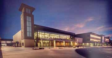
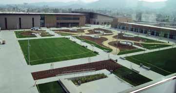
the walls. The situation became more complex at the locations where the embed was to be used for the connection of two drag members that were perpendicular to each other, and each drag member force was to be dragged into different panels at the panel joints. Again, the issue of steel congestion for such embeds being placed into the boundary element of the shear walls had to be proactively addressed at the schematic design phase to ensure there were enough shear walls with a proper system to reduce the drag force to be accommodated in thin tilt-up panel walls.
Three Story Academic Building
The Academic Building, at 250,000 square feet, is a three story structure with a cast-in-place special reinforced concrete shear wall lateral system and structural steel gravity framing constructed at grade-over-spread and wall footings. Floors consisted of composite light weight concrete over metal deck. Tilt-up panels could not be used for this building since it housed all of the classrooms. Ribbon windows were used in a curtain wall system; thus, there were not enough solid wall sections at the building exterior to be utilized as shear walls. Therefore, mostly thick cast-in-place core shear walls were used for the lateral force resisting system.
Two Story Athletic Center Building
The Athletic Center Building is a two story structure (82,000 square feet) with a precast tilt-up special reinforced concrete shear wall lateral system and structural steel gravity framing. The building is located on the sloped portion of the site. Therefore, the north portion of the building is constructed over a partial basement with cast-in-place concrete walls, while the south side of the building is constructed at grade-over-wall and spread footings. Floors consisted of composite light weight concrete-over-metal deck.
Two Story Performing Art Center Building
The Performing Art Center Building (63,000 square feet) is a two story structure with a precast tilt-up special reinforced concrete shear wall lateral system and structural steel gravity framing constructed at grade over spread and wall footings. Floors consisted of composite light weight concrete-over-metal deck.
One Story Academy Building and Support Buildings
The Academy Building and other support buildings are one story structures with precast tilt-up special reinforced concrete shear wall lateral system and structural steel gravity framing constructed at grade-over-spread and wall footings.▪
Project Team
Owner: San Marcos Unified School District Structural Engineer: John A. Martin & Associates Architect, Civil and Landscape: LPA, Inc., Irvine, CA General Contractor: Lusardi Construction Company,
San Marcos, CA
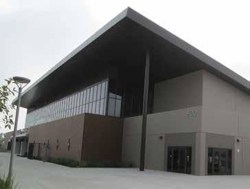
Gymnasium building.
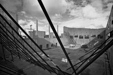
Erected tilt-up panels.
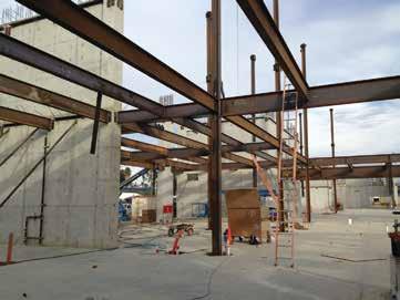
Steel framing and concrete shear walls.
Hossain Ghaffari is a Project Manager at John A. Martin & Associates Inc. and a lecturer at California State University Northridge. He can be reached at hghaffari@johnmartin.com.
Houston’s Hobby Airport Gets New INTERNATIONAL UPGRADE
By David W. Hillery, P.E., Matt Henderson, P.E. and Raxit Patel, P.E.
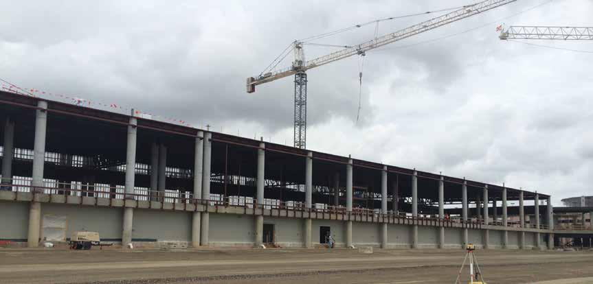
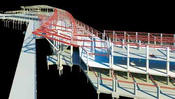
Figure 1. Structural framing at boarding pier.
Houston’s William P. Hobby Airport, named after the 27th Governor of Texas, was established in 1927 as a private airfield, with a main airport passenger terminal added in the 1950’s. Hobby Airport was the primary commercial airport for the city until a new Houston Intercontinental Airport opened in 1969. After that, Hobby continued as Houston’s secondary airport for domestic corporate and private airline service. A major addition to the terminal building was done in 1999, and a new construction project in 2015 added a Federal Inspection Services (FIS) terminal for international travelers. It was mostly Southwest Airlines that made use of Hobby Airport in modern times and now Houston is its seventh-largest-focus city, so it was Southwest that constructed the international terminal there last year. The new terminal, as part of the Houston Airport System (HAS), allows Southwest Airlines to provide service to South America, Central America and Mexico. With 280,000 square feet of new space and five new boarding gates, Hobby Airport has become substantially more than it ever was. Along with the new boarding gates, many features were included in the project. Renovation of the existing lobby, 16,000 square feet of additional concession space, reconfiguration of existing security screening with an increase from 8 to 14 checkpoint lanes, and relocation of office spaces also were accomplished in the new design. An expansion of the Baggage Handling System (BHS) was placed in a new tunnel, shared with other utilities connected to a new central utility plant. The project includes space to allow 800 arriving passengers to be processed through 16 passport inspection stations. Construction costs totaled $156 million. That sum paid for such building features as terrazzo flooring, high ceilings, modern restrooms, a new moving walkway, more collaboration areas, large column-free spaces, and a very visible, tall and artistic exterior tree-like column. The project structural design was done by Henderson + Rogers, Inc. (H+R) in Houston. They worked with the architectural firm of Corgan Associates, Inc. for Southwest Airlines and the HAS to provide the new facilities. There were a number of challenges in design and construction. While new structures were constructed and connections from the older to the newer features were being made, all airport-related traffic, concessions and other businesses had to be maintained without interruption.
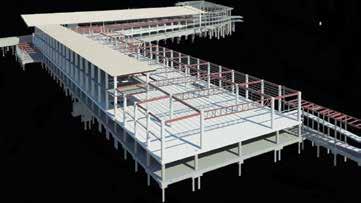
Structural Challenges Due to Existing Conditions
One challenge came in the form of an electrical room in the existing terminal building. This room had been providing essential daily services for critical airport operations. Relocating this electrical room without interruption of airport operations would be too costly. Therefore, the decision was made to keep the room intact rather
than move it. The challenge was twofold. First was the possibility of undermining the room’s foundation during excavation of a nearby underground tunnel. So, a temporary soil retention system, 12 to 14 feet tall, was used (Figure 6 ). This system safely shored up the soil in the excavation, so the electrical room remained in constant use during construction. Second, there was a need for the electrical room’s roof to act as a concourse floor for the new terminal building. The roof could not simply be removed and replaced with a stronger system, because the structure supporting the roof was insufficient to support the new floor loads. The existing single-T precast roof system of the electrical room, built in 1962, was strengthened with additional rebar and structural lightweight concrete. Steel posts were added under the roof to reduce the effective span, and this brought its load carrying capacity up to 100 psf, as required by the International Building Code. All this was done while operations inside the room continued without interruption. The new terminal building is connected to the existing terminal at both the second floor and the roof. New frame structures were strategically placed to minimize added loading to the existing members. Computer software, including RISA-3D, was used to model and analyze the existing building as well as the proposed structures. One result of the analysis was the decision to add new columns which pass through the existing roof down to supports on new cantilevered steel beams. Another connection of the new to the existing structure is where framing for a new cantilevered canopy extended out from the existing 1950 structure. To achieve the desired height of the roof, existing steel columns received new extensions. In addition to RISA-3D, other computer software used for advanced structural analysis and vigorous gravity and lateral design included ETABS and SAFE from Computers and Structures, Inc.
Selection of Structural Systems and Their Benefits
The initial new building foundation was designed with straight-sided drilled piers. However, the design was modified after it was discovered that substantial money could be saved by using auger cast piles instead. Subsequent to a requested pile load test, the pile diameters were reduced from 24 to 18 inches. Incorporating changes could have affected the schedule of the project, so H+R redesigned the foundation and revised drawings in days rather than weeks for a savings in the overall cost of the foundation of approximately one million dollars. The number of piles per column varied from one to four, and pile cap depth ranged from 36 to 42 inches. Four different pile lengths, 40, 50, 60 and 70 feet were incorporated in the design, depending on column locations and base reactions. The longer piles were needed under columns in close proximity to the tunnel and where they supported loads from large roof or floor areas. An existing tunnel, approximately 1,000 feet long, accommodates the airport’s Baggage Handling System and other utilities. A new tunnel was designed to run from the existing tunnel to the new international services, where customs requirements are more complex than for domestic flights. The new tunnel width varies from 22 to 48 feet along its length (Figure 5). The new tunnel’s foundation is a 12-inch thick, cast-in-place, steelreinforced concrete slab thickened to 24 inches below walls. The walls are 12 inches thick and approximately 12 feet tall. The tunnel roof design considered heavy concentrated wheel loads from baggage transfer tugs and other airport vehicles passing overhead. The tunnel roof had to meet a stringent deflection requirement and carried a
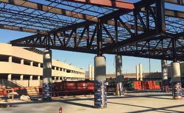
Figure 4. Cantilevered low roof truss supporting high roof framing.
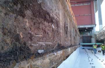
Figure 5. New tunnel floor adjacent to existing tunnel.
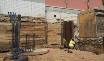
Figure 6. Soil retension system at existing electrical room.
thin-set terrazzo floor finish. The cheapest and most quickly built solution used 12-inch thick hollow-core concrete planks spanning approximately 30 feet and supporting a 4-inch concrete topping slab. At the end of the tunnel where its width was at a maximum of 48 feet, the roof was composed of a cast-in-place, pan-formed, beamand-slab system 25 inches deep. The new terminal building is more than 1,000 feet long and was constructed in three approximately equal sections connected with two expansion joints. The structural system to resist wind loads consisted of concrete moment frames, providing lateral support at the second floor level. Concrete columns at the east end of the building in the ticketing area extend above the second floor and provide lateral support to new steel trusses that are 5 to 8 feet deep. At each continued on page 40
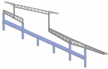
Figure 7. Low roof truss supporting high roof – RISA 3D model.
column line, there are steel columns supported by cantilevered low roof trusses. These columns extend up and connect to 5-foot-deep steel high roof trusses, and provide lateral support to the high roof framing (Figure 4, page 38). At the west concourse, to give the boarding area a feeling of open space, several column locations were skipped, creating longer spans between columns above the second level. 66-foot-long steel trusses were designed to span this length and support the roof framing. Composite frame action between the concrete columns and the 5-foot-deep trusses provides lateral support for the roof. Curved steel embed plates with hooked deformed bars were installed in round cast-in-place concrete columns as connection points for these steel trusses (Figure 8). A key architectural feature for the new FIS facility is a tree-shaped column supporting sloped high roof framing, located strategically
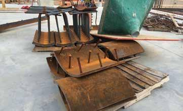
Figure 8. Curved embed plate.
along the existing roadway near the drop-off area of the new terminal building. The tree column has a 4-foot diameter “trunk” which splits into two tapered branches. Like the trunk, each branch is 4 feet in diameter at its intersecting base, and then tapers down to 2 feet at the top. The trunk and branches were rolled and fabricated from half-inch-thick steel plates (Figure 11). Sloped high roof framing at the ticketing area was designed using a combination of long span steel roof trusses, wide flange beams and bar joists supported by steel columns. The high roof steel columns are mounted on the cantilevered ends of the steel trusses of the lower roof. The cantilevered lengths reach up to 35 feet, giving the desired architectural open spaces and visually pleasing high roofs.
Cloud Room
Time-saving webinars and design guides.
Useful design aids for reinforced concrete. On demand.
Visit www.crsi-learning.org for a list of topics.
Get FREE technical and informational downloads at www.crsi.org!
Existing Condition One of the most magnificent areas of the new Hobby Airport houses a semicircular projection of the 1950 terminal building, known as the “Cloud Room.” The structure originally served as an office space for the airport. The entire area (Figure 10) gives the impression, by its size and with electric and natural lighting, of an almost outdoor experience. Passing by the Cloud Room on the way to a gate may make a traveler feel well prepared for flight. However, making this expansive dream come true presented engineering challenges amid the project schedule requirements. The Cloud Room is located above the lobby of the original terminal, and the desire was to remove columns and provide more uninterrupted space in the area below. Its floor structure consists of a concrete slab on composite metal deck supported by steel floor trusses. The floor trusses were cantilevered out over steel pipe columns with ends tapered out to a mezzanine perimeter. The columns below were arranged in a colonnade pattern bearing directly on the lobby floor.
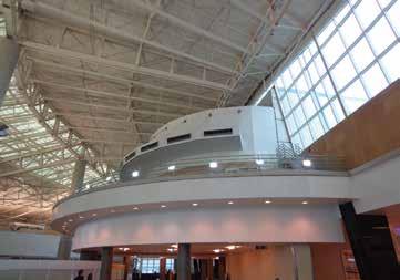
Figure 9. Cloud room – existing condition.
The request was to eliminate these columns to allow a smoother flow of pedestrians, and to increase the beauty and atmosphere of the area. The architect originally suggested removing the 1950 Cloud Room altogether. However, this would require relocating existing mechanical ducts, electrical, and plumbing equipment serving the main lobby, which would have required an interruption of heating and cooling for a substantial duration. This would come at a much greater cost to the owner than the actual solution which was implemented. Structural Solution The solution was to support the Cloud Room from the roof structure and then remove the columns below. H+R designed a system of beams and steel pipe hangers in the same geometry already present in the colonnade orientation, and coordinated with the existing MEP system. The hangers were spliced with the existing pipe columns extending up to the 1999 addition’s long span steel trusses. To minimize the additional weight added to the high airport roof’s steel trusses, existing miscellaneous framing at the penthouse floor and roof structure was removed, and an in-plane truss system was designed to provide the lateral stability for this hanging penthouse structure. The existing roof trusses were analyzed using 3D analysis software (RISA-3D) and some trusses had to be reinforced. Subsequent to the installation of the hanger supports, and with the new reinforcement in place, the existing columns bearing on the lobby floor were removed. The process was well-planned and sequenced to minimize impact loading. The general contractor monitored deflections of the high roof trusses during this procedure, and all measured less than ½ inch, well within the code prescribed limits. The solution prevented interruption to MEP services and proved economical as well as architecturally beneficial to the project.
If you find yourself traveling in the near future, on a domestic or international flight into or out of Houston, you will be able to enjoy with some enthusiasm and interest what might otherwise be a mundane, ordinary trip out of town. The enterprises that process passengers on their way with efficiency have made it possible for us all to travel in comfort. This is due to the cooperation and coordination of many inter-related facilities found at the airport, all housed in massive structures of concrete and steel.
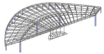
Figure 10. Cloud room – RISA 3D model.
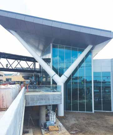
Figure 11. Tree column.
In Houston’s Hobby Airport, these facilities were made possible not only by HAS and Southwest Airlines, but by architects, structural engineers and builders who met many challenges and solved them with creativity, advanced technology and hard work. When you visit Hobby Airport on your way through Houston, take a look around and consider all the elements that went together to make such an important aviation facility beautiful as well as functional.▪
David W. Hillery, P.E., is a Senior Structural Engineer working in Construction Administration for building projects with Henderson + Rogers. He can be reached at dhillery@hendersonrogers.com. Matt Henderson, P.E., is Principal-in-Charge at Henderson + Rogers. He can be reached at mhenderson@hendersonrogers.com. Raxit Patel, P.E., is a Project Manager for Henderson + Rogers. He can be reached at rpatel@hendersonrogers.com.


