31 minute read
STRUCTURAL SYSTEMS
discussion and advances related to structural and component systems For centuries, bridges and other structures were big, bulky, visually disruptive hulks. Stone, iron, and concrete made them symbols of strength and stability. Solid construction helped people feel more confident about crossing or entering them. Over time, they became lighter and more transparent. Innovative designs leveraging glass, plastic, cable, and sometimes environmentally-friendly recycled refuse replaced more solid materials to create bridges and buildings that are light, airy, beautiful – and stronger than their predecessors. What led to these enhancements? The fact that beauty lies in the eye of the beholder. Designers and engineers are never satisfied with what they see and are always imagining the future. Let’s look at some notable historic bridges that took the industry to the next level, and a few of the exciting designs currently on drawing boards that could propel it into the future.
Bridges with Brawn
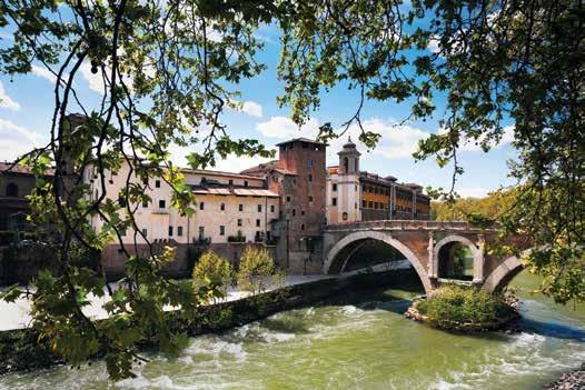
How Beauty Beat Brawn Back when bridge construction was a novel concept, builders understood few basic engineering concepts. Taking the Bridge- They knew that the load placed on the surface of a Building Prize bridge had to be distributed to support structures. To compensate for the lack of more sophisticated By Jeremy Herauf scientific or engineering knowledge, designers naturally turned to bulk to enhance the strength of their structures. Over time, simple plank bridges, even hefty ones, proved to be ineffective, especially over vast expanses. Arch bridges were far more durable. The first ones were dense and heavy. Eventually, builders found ways to make them lighter, more attractive, and better integrated into their environments. Three of the oldest arch bridges in existence illustrate this progression. Although it cannot be officially dated, the Arkadiko Bridge, located on the Peloponnesus in Greece, is believed to be the oldest arch bridge still in use. Dating from the Greek Bronze Age (32001050 B.C.), its heavy-duty design is a testament to its age and the primary reason for its longevity. The Caravan Bridge is the world’s oldest reliably dated bridge, going all the way back to 850 B.C. It is a stone arch span over the Meles River in Izmir, Turkey. Clearly, bridge designers had made strides to improve functionality, design, and environmental integration. The Pons Fabricius has connected Tiber Island to the heart of Rome since 62 B.C., the oldest bridge in the ancient city. It includes two broad arches, supported by a central pillar featuring a smaller arch built of ancient volcanic rock with brick and marble facing. Almost 800 years of bridge-building experience enhanced its beauty and effectiveness. Despite the strength and stability of these solid arch structures, they had limits. As cities grew and became more congested, newer bridges were needed that could function in densely-populated, interconnected urban environments.
Early Innovators
As a next step, bridge builders turned to the emerging worlds of science and technology to find innovations to lighten, lengthen, and increase the strength of the bridges they built. Thought leaders like Leonardo da Vinci came up with
Jeremy Herauf is the President of Bridge Masters, Inc., a company with over 40 years of experience installing and repairing bridge utilities. He has 20+ years of experience as a machinist, mechanic, and supervisor in the manufacturing industry, and served eight years in the United States Army. He can be reached at info@bridgemastersinc.com.
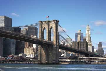
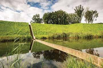
Brooklyn Bridge, New York. Opened in 1883. Moses Bridge, Halsteren, The Netherlands. Built in 2010. (By Digital Eye [Own work] CC BY-SA 4.0, via Wikimedia Commons)
designs that imagined what a bridge could be in fresh new ways. However, like many scientific experiments, some failed during, or shortly after, construction. The Brooklyn Bridge was destined to be an engineering and design marvel from the day ground was broken in 1869. It is one of the oldest combined cable-stay suspension bridges, having survived more than 130 years under grueling vehicular, pedestrian, and train traffic. The cutting-edge design and new construction methods led to many injuries and deaths from decompression sickness (“the bends”) and other causes. The key reason the bridge has survived when so many similar ones failed is that it was built to be four to six times stronger than it needed to be. The Honeymoon Bridge crossed the Niagara River, connecting Niagara Falls, New York, to Niagara Falls, Ontario, from when it was completed in 1898 until 1938. It was an upper steel arch bridge that was considered stable, despite threats from its unique location and ice that formed in the winter. A great windstorm during the winter of 1938 pushed a record amount of ice against the abutments, causing the bridge to collapse. The original Tacoma Narrows Bridge was a grand engineering experiment and renowned bridge failure. At the time of its construction in 1940, it was one of the longest and slenderest suspension bridges in the world. It crossed a challenging section of Puget Sound in Washington State. Winds in the sound caused the bridge to vibrate, even during construction, and the structure collapsed less than six months after it opened. The bridge is still referenced in textbooks as an example of why it is critical to avoid aeroelastic flutter.
The Present
Most people view today’s modern bridges as visual masterworks. They are stunning to look at and enhance the everyday travel experience. However, underlying these beautiful structures are amazing engineering enhancements that make them stronger and safer than those built in earlier eras. The Chords Bridge has completely transformed the skyline in Jerusalem. This almost invisible, crystal-like structure was modeled on the concept of David’s lyre. It is a major rapid transit link that carries trains and pedestrians in a glass-sided structure. An innovative side-spar cable-stayed design allows the bridge to flow in a graceful curve, keeping it visually light, yet incredibly strong and stable. Who says a bridge has to be in the air or even be visible? The Moses Bridge in The Netherlands carries pedestrians across a canal under the water line in a trench that is virtually invisible at certain angles. It leveraged design and construction techniques similar to those used in dams to hold the water back. The name of the bridge refers to the biblical story of Moses parting the water. Everything that makes the design of the Kurilpa Bridge in Australia so light and attractive also makes it robust and stable. It is a multiple-mast, cable-stay structure based on advanced principles of tensegrity. This produces a solid synergy between balanced tension and compression components. The dazzling light show that makes the bridge so stunning at night is powered by a solar grid that contributes excess power to the city of Brisbane.
The Futurists
What do bridge designers envision for the future? Much like the rest of the art and design world, they are creating structures that break all the rules – or combine them in new and innovative ways. This could lead to structures that are lighter, more beautiful and stronger than ever. In today’s environmentally-sensitive world, many are turning trash into structural treasures. The basic plank bridge could get new life with new technology. It could be resurrected in the planned Econtainer Bridge that will connect Route 461 to Ariel Sharon Park in Israel. The park brings harmony to the urban landscape and nature, so this sustainable design made of used shipping containers is perfect for the site. The design even includes photovoltaic solar cells that will light the bridge and surrounding area at night, combining the most ancient of bridge structures with the latest environmentallyfriendly concepts. The Art Bridge is planned as a connector across the Los Angeles River, as well as a commentary on this famous body of water. Another plank design, the bridge will mostly be built from reinforced river trash, including bottle glass, cans, recycled tires, scrap metal, and more. Bridge lighting will be done in a completely environmentally friendly way. The brutal design is a reflection on the history and current state of the river, which has been significantly altered from its natural state. This concept for a new London Bridge takes bridge design to a higher level. Not only will people cross it, but they can also live, farm, and shop on it as well. The bridge becomes a completely environmentally friendly, selfcontained universe. The complex, integrated, lighter-than-air concept will help ensure the survival of the structure should something unexpected happen. The lesson to learn from all this? Bridge designers and engineers can never stop looking for new and innovative ways to build beautiful, strong structures. Technology has made it possible to build bridges that are lighter, stronger, and more sensitive to their environments. Beauty has always triumphed over brawn.▪
ALBINAYARD
North Portland CLT Office Building
By Blake Patsy, P.E., S.E.
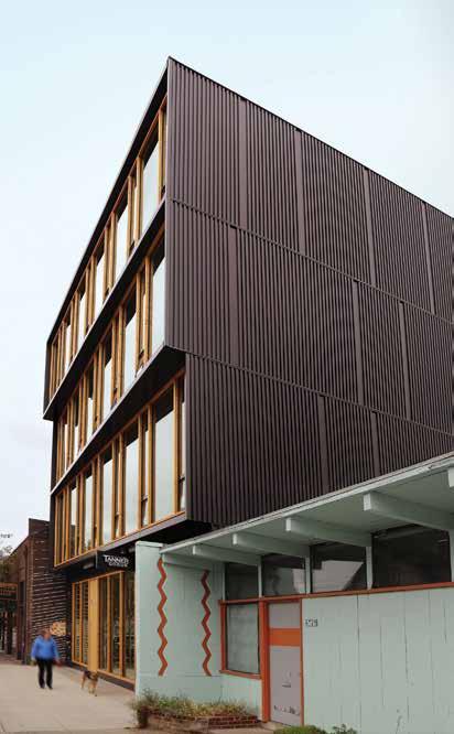
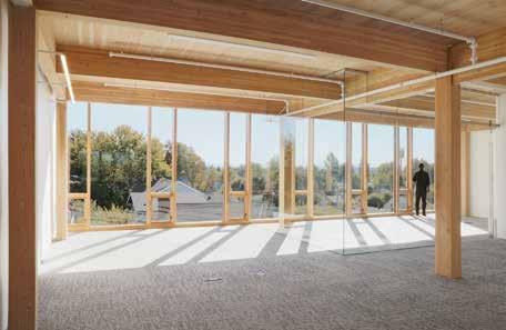
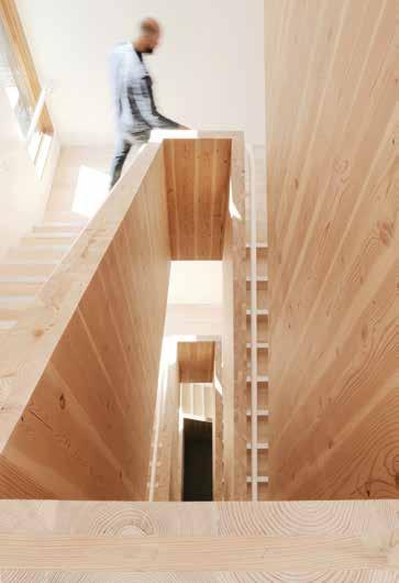
Albina Yard, the first building in the U.S. to use domestically produced cross-laminated timber (CLT) panels as the primary structural building element, has recently wrapped up con struction in North Portland’s Boise-Eliot district. The project is a 4-story, 16,000 square foot creative office building designed to accommodate small businesses looking to work in an environment with natural light and exposed wood. Providing an energy efficient workspace, and its shared conference rooms and courtyard, Albina Yard will be at home in the environmentally-conscious and communityoriented Mississippi Avenue neighborhood. The primary feature of the project is its exposed mass timber structural frame consisting of glue-laminated (glulam) beams and columns, and CLT floor/roof panels. Great care was taken in the design of the timber-to-timber connections to create a clean and modern timber aesthetic.
Significance
Albina Yard is unique because the structure is almost entirely composed of mass timber elements, involving the early implementation of CLT, and also unique in its local “forest to frame” story. The story is framed by the sourcing, manufacturing, and fabrication of the timber components in the Northwest, along with the local development and design team: Reworks, Lever Architecture, and KPFF Consulting Engineers. At the forefront of the implementation of mass timber buildings in the U.S., the design team faced a number of atypical challenges and is paving the way for future mass timber projects to come. These challenges included addressing regulatory hurdles and seismic requirements (as it relates to the CLT diaphragm use) for the utilization of a relatively new product like CLT. Challenges also included understanding the currently limited CLT supply chain and fabrication capabilities in the U.S., navigating pricing challenges, and convincing risk adverse sub-contractors to price the job fairly. Aaron Blake, owner of Reworks and Albina Yard, LLC speaks to the many benefits of working with CLT: “We see Albina Yard as a catalytic project, paving the way for broad market adoption of mass timber construction in Portland and throughout the country. Mass timber products derived from sustainably managed forests allow us to build faster, stronger and less expensively with fewer environmental costs. Albina Yard is a proving ground for this new building technology, giving design teams and construction crews an opportunity to gain expertise that can be applied to much larger projects.”
Sourcing & Fabrication
The goal from the outset of the project was to incorporate locallysourced timber products into the building. In particular, this included CLT panels manufactured by D.R. Johnson Lumber Co. out of Riddle, Oregon. CLT is manufactured by layering 2x members stacked
Exterior.
crosswise (at 90 degrees). Each layer is glued together to form panels up to 10 feet wide by 40 feet long. The perpendicular stacking creates a very strong, dimensionally stable product with two-way spanning capabilities. These properties and the large panel sizes create a distinct advantage over other timber flooring products considered. Thomas Robinson, the founder of LEVER and architect of Albina Yard and another CLT project, Framework, is a strong proponent of CLT and describes a few of the benefits: “The building design reveals the material qualities that are inherent to these new and innovative mass timber technologies. Because of the strength of the CLT panels, we can span longer distances with fewer beams and employ large, angled cantilevers that give the building façade a dynamic presence.” When the project started, D.R. Johnson was still in the process of completing the testing to receive ANSI/APA certification of their CLT panels, the first such certification for domestically produced panels. Anticipating approvals would be received, the design team created a framing layout customized to the panel sizes capable of being produced, which was a maximum of 10 x 24 feet at the time. This included forging a relationship between D.R. Johnson, who also supplied the glulam beams and columns, and Cut My Timber from Portland, Oregon, one of the few outfits with computer-numericcontrolled (CNC) machinery capabilities in the Northwest.
Scan to see a video of the construction.
Interior.
The Frame
The gravity structure for the project includes gypcrete-topped CLT floor panels supported by a glulam post-and-beam structure, with custom concealed timber-to-timber connections. The design of these connections required meaningful collaboration among Lever Architecture, KPFF Engineers, and Cut My Timber to determine realistic tolerance expectations and understand CNC capabilities. Ideally, all of the connections would have been fitted up in the shop to ensure a smooth installation on site. Unfortunately, due to schedule constraints, this was not possible for the first delivery of glulam members. The team discovered first hand that the timber could be fabricated to much tighter tolerances than the steel connectors themselves. Simple variations in weld sizes thus required field modifications to timber members receiving the steel connectors on the first level. The fabrication of subsequent glulam shipments was modified to allow for greater variations in the welds, resulting in a smoother installation process. The prevalence of concealed connections is only going to grow with the increased adoption of CLT. This will include the use of mass timber in fire rated construction where wood cover at the connections will serve to protect the concealed steel connectors. Thus, the ability to coordinate the connection design with the end fabricator will become ever more important.
Seismic
Portland is in a seismically active region and, as a result, Albina Yard is required by code to meet specific seismic performance objectives. Even with the adoption of the 2015 International Building Code (IBC), which recognizes CLT as a material for the first time, there is still no direct code guidance on how to adapt CLT for use as a shear wall element or horizontal diaphragm. As a result, the design team initially sought to use CLT as a gravity support member only to avoid potential schedule delays associated with a performance-based design. Originally, the vertical lateral force resisting system was to consist of light framed plywood shear walls and the CLT floor panels were to be topped with a plywood sheathing layer to create a horizontal diaphragm conforming to existing seismic provisions. During the design process, the State of Oregon came out with Statewide Alternate Method, No. 15-01 Cross-Laminated Timber Provisions, which brought forward the CLT provisions in the 2015 IBC and included conservative seismic design parameters for CLT as seismic force-resisting elements (Response Modification Factor, R=2). Working with the Statewide Alternate Method, and in close collaboration with the State of Oregon Building Codes Divisions, the excess plywood sheathing layer was removed to allow the CLT to act alone as the horizontal diaphragm. The diaphragm connections, CLT spline connections, and CLT-to-drag connections were designed to remain essentially elastic. The design team decided to continue with plywood-sheathed shear walls, rather than switch to CLT shear walls, due to the added ductility and associated higher Response Modification Factor this system provides (R=7).
Outside the State of Oregon, CLT can still be used as a lateral force-resisting element through the Alternate Material and Method provisions in the code which allows a performance-based design of these elements. This will require additional research and analysis on the Structural Engineer of Record’s part, and the path to approval should be coordinated with the Authority Having Jurisdictions from the outset of design. continued on next page
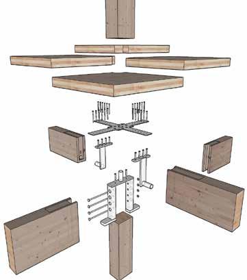
CLT concealed beam/column assembly. Construction.
Construction
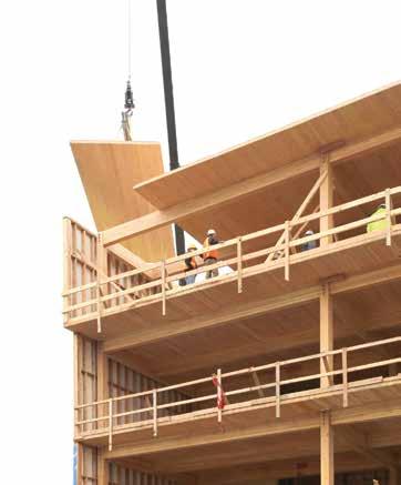
There are major advantages to the use of CLT in mass timber construction, such as reduced construction schedules and reduced manpower required. However, it does require significantly more pre-construction coordination and planning on the A/E/C team’s part, in comparison to a typical project. On the design team side, this includes working with the manufacturer to develop an efficient panel layout and coordinating all MEP penetrations in advance of fabrication to limit field cutting of the panels. An accurate 3D Building Information Model (BIM) is essential to this process to avoid potential conflicts and can prove helpful to the manufacturer for pricing and development of shop drawings. Understanding and coordinating acceptable tolerances between trades is also crucial. With the aid of CNC machinery, the tolerance capabilities of the timber components can be equivalent to concrete or steel construction. As a result, any additional tolerances which can be built into the design, particularly at the interface of different materials, can help ensure a successful project. For efficient installation, the contractor will want to pre-plan everything down to the order the panels come off the truck to speed up erection. If planned correctly, the installation can go extremely quickly. For Albina Yard, Timberland Framing Contractors installed the first level of CLT, approximately 4,000 square feet, in 4 hours. By the time they reached the 4th level, they had completed installation at this level in 2 hours with a crew of 5.
Future
The demand for mass timber construction, specifically the use of CLT, is on the rise and is only expected to grow once the schedule benefits and associated cost savings are fully realized for development and construction. Notably, another collaboration with this team is The Framework Project, a proposed 12-story mixed use, mass timber building in Portland, Oregon, which was named the West Coast Winner of the USDA-sponsored U.S. Tall Wood Building Prize Competition (https://tallwoodbuildingcompetition.org). Valerie Johnson, President of D.R. Johnson Lumber, reminds us of additional benefits. “Tall wood buildings have a great environmental story, and advanced wood products make better use of our state’s greatest natural resource. Increased use of these products in taller wood buildings means more jobs for rural communities that have been experiencing an economic decline for years.”▪
Blake Patsy, P.E., S.E., is currently the Managing Principal for KPFF’s Portland structural office. Due to his expertise in seismic design and his familiarity with Portland, Blake serves on the Structural Advisory Board for the City. Blake can be reached at blake.patsy@kpff.com.
All graphics courtesy of LEVER Architecture.
Project Team
Project Owner: Albina Yard LLC Structural Engineer: KPFF Consulting Engineers Developer/General Contractor: Reworks Architect of Record: LEVER Architecture Glulam/CLT supplier: D.R. Johnson Lumber Co. CNC Machining: Cut My Timber Lighting Designer: O-LLC Project Support: Woodworks


ECONOMICAL LONG-SPAN HIGH-RISE
By Cary Kopczynski, P.E., S.E., FACI and Joe Ferzli, P.E., S.E.
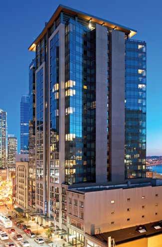
Viktoria Tower, at the heart of downtown Seattle, fosters urban living with 249 upscale apartment units ranging from studio to 2 bedrooms, six levels of parking above grade for tenants, and 3,700 square feet of street-level retail which spurs community revitalization. e project is LEED certi ed and incorporates an assortment of eco-friendly materials, which utilize sustainable building practices. Viktoria is a 25-story upscale apartment tower with no internal columns, creating an open oor plan that o ers spacious layouts w ith maximized usable square footage. Originally conceived as a condominium tower, the project was reinvented midstream to accommodate swelling demand for apartments from young urban renters. One of Viktoria’s most prominent features is its expansive oor plans. e structure has no restricting inner columns from the core to the exterior glass line, providing completely open interior space, architectural exibility, and enhanced views from each unit. Viktoria’s socially-focused amenities include a rooftop terrace with outdoor BBQ stations, party room, indoor sky lounge, theater room, and a tness center. With dazzling 360-degree panoramic views, the entire 25th oor is devoted to a resident lounge. Featuring an evergreen tree which pierces through an oculus opening, a dramatic butter y roof, which cantilevers more than 20 feet from the enclosed portion of the sky lounge, adds a unique charm to the modern high-rise building.
State of the Art Structural Design
Cary Kopczynski & Company (CKC) is the structural engineer of Viktoria. e structural system consists of cast-in-place concrete with post-tensioned oor slabs and a shear wall core for seismic and wind resistance. Using high strength concrete in the lower level core walls, the column sizes and concrete volume were e ectively decreased. e architectural revisions associated with the conversion from condominiums to apartments impacted the entire design team. Additionally, the upgrade from the 2003 International Building Code (IBC) to the 2009 IBC particularly a ected the design of shear walls. Substantial cost savings were achieved by modifying the core design, relocating subterranean parking above grade, and incorporating several value-engineering modi cations to the structure. In retooling the building, the unit count was increased and the average unit size decreased. With a tight building footprint, the engineer was compelled to nd a creative solution to attain the owner’s vision of large, open oor plans with minimal structural obstructions. After a number of structural frame iterations, CKC proposed an innovative solution to eliminate all internal columns. Slab spans of nearly 40 feet from the central core to the exterior glass line were made possible by increasing slab thickness around the perimeter of the core. is provided completely open living units and parking layout without structural obstructions. e long span oor system was carefully analyzed using a hybrid post-tensioned concrete where precompression forces and tendon pro les were designed to balance gravity loads.
Viktoria Tower, Seattle.
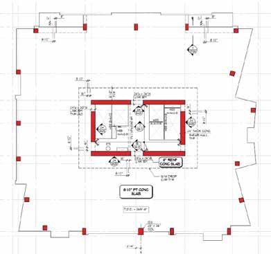
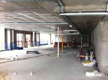
Column free space. Core wall vertical reinforcement ratio demand.
Due to proximity to adjacent buildings, the loads were minimized at the building perimeter to avoid settlement e ects. e engineer also minimized sideway motion during an earthquake to eliminate the possibility of contact with the surrounding buildings. State-of-the-art nite element and analysis tools were used to predict building drift and diaphragm de ection limits. During construction, the contractor discovered that the foundation of the adjacent building was crossing over the property line. e foundation of Viktoria was therefore carefully adjusted to bridge over the existing foundation. Close communication and synergistic coordination between the design and construction teams empowered CKC to make a rapid design change while keeping the tight construction schedule on track.
Design and Structural Benefi ts of Drophead
With urban real estate at a premium, maximizing usable interior space and view from each unit is critical. Creating open layouts in concrete towers with at plate slabs is di cult due to the need for internal columns to keep slab spans within reasonable ranges. e Viktoria design team developed an innovative shear wall core design which provided a way to eliminate all interior columns, increase architectural exibility, and improve structural e ciency. A column-free space was achieved by thickening the slab layout from 8½ inches to 16 inches for a distance of six feet at the corridor around the core perimeter. is sti ened the slab and created a unique core “drophead” system that eliminated the need for internal columns. Spans were increased to nearly forty feet, creating a column-free space throughout. e drophead eliminated transfer beams, which would have been otherwise required to shift, or “transfer” the location of interior columns as they pass through the lower retail, lobby, and parking levels. e Viktoria tower obstruction-free layout also streamlined the installation of non-structural interior walls, eliminating the need to build around restrictive columns. e strategic incorporation of post-tensioning allowed the use of 8½-inch slabs despite the ultra-long spans. is minimized structural mass, and consequently seismic forces, which bene tted the columns, core walls, and foundations. Additionally, high-strength concrete in the lower level core walls e ectively decreased the column sizes and total concrete volume. With close communication in the early design process, this innovative core design created positive outcomes for all involved in the design of Viktoria. e owner gained additional leasing space, the design team bene ted from increased architectural exibility and improved structural e ciency, and the contractor was able to expedite the construction process. Despite several engineering challenges, CKC’s creative solution helped the design team achieve the owner’s vision for the project. e result was a state-of-the-art modern residential tower with no internal structural obstructions.
Team Collaboration
Viktoria is an excellent example of successful teamwork. e owner, architect, engineer, and contractor worked closely from the early design phase to create a one-of-a-kind building that not only compliments the architectural intent but also meets the reality of the business world. continued on page 34
Weber ompson is the architect responsible for Viktoria’s architectural design, interior design, and landscape architecture. Viktoria is designed for those who want to enjoy downtown living without the commitment of purchasing. To that end, the architect integrated upscale yet approachable design elements with a neutral and elegant Northwest palette throughout. Its slender architecture is streamlined with vivid vertical metal panels and layers of glass curtain wall. Its strong verticality is accentuated with precast concrete, which creates a sense of symmetry and balance to the design. All private decks were transformed to bay windows to capture additional leasing area, to create spectacular views right o the units’ dining rooms, and to foster active social amenities. Turner Construction was the general contractor responsible for the overall coordination and day-to-day oversight of the project. Safety was of utmost importance to Viktoria’s construction team. Turner implemented numerous safety protocols, such as subcontractor screening, daily foreman meeting, and ladder policy. Close communication between Turner Construction, Weber ompson, and CKC was the key to the successful implementation of Viktoria’s unusual core design. Despite the simplicity of its appearance, the increased thickness of the slab required substantial work on the special formwork and shoring. Nonetheless, the construction team went above and beyond to adapt to its application quickly. e engineer minimized the constructability challenge by creating a buildable design and working synergistically with the contractor. Even though extra work and concrete were necessary to build Viktoria’s slab/core system, the design created signi cant savings in material and schedule. Elimination of internal columns produced numerous bene ts, and the design was well-received by the contractor. e owner and architect applied the savings to other aspects of the building that contributed to Viktoria’s market success.
Conclusion
e creative use of a unique core drophead system and post-tensioned concrete resulted in an elegantly e cient overall system that pioneered a new approach to concrete building design in high seismic regions. rough careful coordination between the design and construction teams, the building was constructed e ciently and economically and exceeded the expectations of all involved. Viktoria’s drophead system increased the dead load on the lateral system and subsequently reduced drift and tensile reinforcement demands.▪
Cary Kopczynski, P.E., S.E., FACI, is Senior Principal and CEO of Cary Kopczynski & Company (CKC). Mr. Kopczynski serves on the Board of Directors of both the American Concrete Institute (ACI) and PostTensioning Institute (PTI), Chaired the PTI’s Technical Advisory Board for six years, and served on ACI Committee 318 for several building code cycles. Mr. Kopczynski can be reached at caryk@ckcps.com. Joe Ferzli, P.E., S.E., is a Principal at Cary Kopczynski & Company (CKC), located in Bellevue, Washington, and the Senior Project Manager for Viktoria. Mr. Ferzli serves on the Board of Directors of the American Concrete Institute (ACI) Washington Chapter. Mr. Ferzli can be reached at joef@ckcps.com.
ADVERTISEMENT–For Advertiser Information, visit www.STRUCTUREmag.org

FIBERGLASS... THE STRUCTURAL ALTERNATIVE


FIBER REINFORCED POLYMER COMPOSITE STRUCTURAL SHAPES & PLATE

VISIT STRONGWELL.COM/STRUCTURE TO LEARN MORE


276-645-8000 • info@strongwell.com • www.strongwell.com
The World Leader in Pultrusion and Pultruded FRP Structures & Shapes
STRONGWELL PRODUCTS PROUDLY
ISO-9001 Quality Certified Manufacturing Plants
DALLAS FIRE STATION #27
Rebuilding with Site Constraints
By Akshai Ramakrishnan, P.E.
Courtesy of Thomas McConnell, Perkins + Will
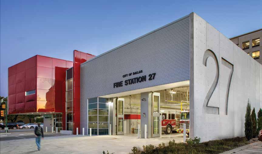
Upon opening its doors in December of 2015, Dallas Fire Station #27 was recognized as special in a number of ways: 1) It is one of only four currently operational multi-story fire station facilities for the Dallas Fire-Rescue Department (DFRD), and the first one built in the last 50 years; 2) Very few fire stations are composed of a concrete frame superstructure; 3) Only a handful of fire stations are LEED registered (Fire Station #27 is currently pursuing Gold certification); 4) No other Dallas fire station has an underground parking garage; and 5) The multiple points of entry required for the apparatus bay is unique, especially when it located at a very busy urban intersection. The structural challenges presented by these last two features are addressed in the following discussion. But first, here is a brief history of how these site constraints developed. Considering the fifty-seven fire stations that the DFRD manages for the city of Dallas, Texas, it can be difficult for an individual station to achieve distinction. With such a long history of service covering a large metropolitan area, the DFRD has utilized dozens of facilities to house their dedicated personnel during more than 140 years of operation. Despite the simplicity, utility, and efficiency these facilities are tailored to meet, an exceptional one pays special homage to the fine men and women who vigilantly maintain the protection of the community as their primary focus. The 23,000 square-foot building did not aim to accomplish each of the feats indicated above purely for the sake of differentiating itself from other facilities. The driving factors for some of these accomplishments were a result of necessity. The original station, which opened in 1948, was a single-story structure of a little less than 5,000 square feet which served the fringes of the growing city of Dallas. However, as the surrounding community began to urbanize, and the quantity of single family and multi-family residences and supporting commercial development increased exponentially, it became apparent the facility needed to be modernized. The existing lot encompassed just over 18,500 square feet. To accommodate new quarters, an apparatus bay, parking allotment for firefighters and visitors, and ingress/egress that could meet the minimum requirements for apparatus functionality and access to the street, the primary challenge was already evident. The lot was tucked into the east end of Preston Square, aligned with the southwest corner of the intersection of the Northwest Highway thoroughfare and Douglas Avenue, making the difficult task even more daunting. To the south of the lot (beyond the typical easement) was Berkshire Lane, a public street. Directly to the west of the property
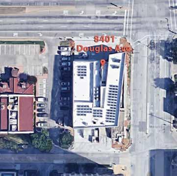
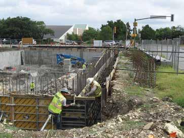
was an operating restaurant that, despite accommodating the City as much as possible, required functioning parking spaces and vehicle access to remain operational throughout the duration of demolition and construction activities. The design scheme to accommodate all of the site constraints required building vertically while maintaining grade level access to the apparatus bay to preserve efficient response times. This meant that building a basement level to move the required parking below grade was the most feasible solution. Within this solution, it was deduced that the access ramp would need to be a single entrance/exit ramp so as not to conflict with the apparatus operation, and so as not to limit the quantity of parking spaces available to the eighteen firefighters Station #27 was intended to house. A more than 14-foot deep excavation was required to set the basement level and install the footings supporting the concrete frame and walls. The extent of the 7,500 square foot basement was squeezed into the northeast corner of the site, with basement walls located four feet from the east property line and 13 feet from the north property line. This was to allow the apparatus bay to align on the west side of the building, the foundation of which was to bear on compacted subgrade backfilled against the west basement wall. This facilitated access for apparatus to enter the facility and turn out onto the busy intersection that handles more than 29,000 vehicles per day. Due to such a high traffic count and landlocked site, the excavation required the installation of a temporary earth retention system along the north and east sides of the basement. This allowed for continued use of adjacent roads without restriction throughout the construction. The solution implemented by Ancortex Inc. and AP Engineering Consultant, Inc., was a cantilevered soldier pile retention system with timber lagging, constructed of W6x25 piles embedded six feet into the limestone stratum and encased in a ten-inch diameter grout filled bore spaced at 4 feet on-center. The footing for the east basement wall extended 12 inches beyond the exterior face of the wall but, due to the eccentric loading of the upper-level structure in some locations, the footing extended a minimum of 24 inches from the exterior face of the wall for about 50 feet. As a result, a two-sided forming system by Doka USA was utilized for the basement wall construction, with traditional diagonal strut bracing onto the basement slab to brace for loads imparted by concrete installation and backfill placement between the lagging and the basement wall. This also proved to be a difficult task, as utility easements ran along the east edge of the site and a workable cavity space was required to apply waterproofing. A low strength flowable fill (gravel mixture) was used for backfill because of the lack of space for compaction. The underlying soils at this site consisted of a stiff clay for the upper four feet, weathered tan limestone for the next six feet, and a hard gray limestone layer occurring approximately 10 feet below grade. This soil/ rock profile was a positive, as it allowed the use of shallow footings bearing at the basement level. However, this required excavation of between four to nine feet of limestone materials which necessitated the use of heavy rock excavating equipment. Furthermore, a few (granted simpler) challenges were presented because the apparatus bay slab was bearing on compacted subgrade. The west wall of the apparatus bay was flushed up against the property line adjacent to the restaurant. To maintain similar foundation bearing for the structural cast-in-place concrete wall along this side, drilled concrete piers bearing on the limestone were installed offset from the wall so as to have clearance away from the plat restriction. Eccentrically loaded pilasters were designed with the grade beam placement so that a cold joint could be placed for the wall construction. The width of the apparatus bay extended a few feet over the westernmost basement wall, which was constrained due to the two-way access to the parking level. That basement wall required the design of the hydrostatic forces behind the wall (considering a drained condition as perforated drain pipe ran along the bottom of the wall) with an additional surcharge load of 250 psf for the apparatus bay. The north end of the parking garage roof structure extended beyond the footprint of the building above, which presented another challenge. The concrete joist floor structure for the 1st level required a 4-inch depression at the building transition to exterior parking and driveway to accommodate a paver system, and needed to be sloped at 2% grade away from the building. The depth of the structural system was limited to maintain minimum overhead clearance in the garage for vehicles. This resulted in the use of wider joists and narrower pans. To mitigate potential overhead conflicts, building utilities such as fire sprinkler lines were run between the narrow pan joists. Trunk lines were sleeved or cored through the joists. As a result of a portion of the 50,000-pound apparatus being able to turn out over the structured garage roof, the joists and girders in the end bay required that the design apply 2/3 of the load applied on an individual axle and additional analyses involving the moving wheel loads. In summary, Fire Station #27 achieved its primary goal: to provide an efficient and modern facility for the brave firefighters who call it home, while also standing out as a monumental structure that honors all firefighters who protect the city of Dallas.▪
Akshai Ramakrishnan is an Associate of JQ Infrastructure, LLC in the Houston office. He can be reached at aramakrishnan@jqieng.com.
The online version of this article contains references. Please visit www.STRUCTUREmag.org.
Project Team
Owner: City of Dallas, Texas Structural Engineer of Record: JQ Engineering, LLP, Dallas, Texas Architect of Record: Perkins+Will, Dallas, Texas General Contractor: Bartlett Cocke General Contractors


