46 minute read
Historic Structures


significant structures of the past
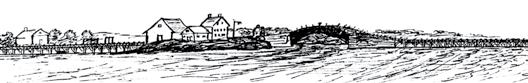
Piscataqua Bridge
By Frank Griggs, Jr., Dist. M. ASCE, D. Eng., P.E., P.L.S.
Dr. Griggs specializes in the restoration of historic bridges, having restored many 19th Century cast and wrought iron bridges. He was formerly Director of Historic Bridge Programs for Clough, Harbour & Associates LLP in Albany, NY, and is now an independent Consulting Engineer. Dr. Griggs can be reached at fgriggs@nycap.rr.com. The Piscataqua Bridge across the Great Bay of the Piscataqua River is located six miles west of Portsmouth, New Hampshire, and was built in 1794 with a span of 244 feet. It was the longest span bridge in the United States when it opened, holding that record until Lewis Wernwag built his Colossus Bridge across the Schuylkill River north of Philadelphia in 1812 with a span of 340 feet. Timothy Palmer had built bridges across the Merrimack River in Massachusetts, and was a pioneer in long span wooden truss bridge design and construction when he was called to build the most difficult part of the Piscataqua Bridge. Palmer’s first bridge was the Essex–Merrimack Bridge, west of Newburyport across the Merrimack River, that opened in 1792 (June 2013 issue of STRUCTURE magazine). That bridge was followed by a bridge at Andover (now Lawrence) Massachusetts across the same river in 1793. The bridge was built “to open a communication between Portsmouth and the interior of the state, and to divert its trade from Boston, Newburyport, and Portland, by which it has hitherto been engrossed. This bridge lies in a direct course to the heart of the state; and a turnpike road was originally intended to be opened from it to Concord on the Merrimack, and thence to the Connecticut River.” The Turnpike had been started in 1791 to connect Concord, the capital, with tidewater at Durham, New Hampshire. The users of the turnpike found, however, that a direct land route to tidewater at Portsmouth would be most advantageous and urged the construction of a bridge across the Great Bay connecting Durham with Newington. The initial petition to the legislature was submitted in December 1792 for authorization to build a toll bridge, and a survey made of the crossing and the results were published in the Portsmouth Herald on June 4, 1793 as follows:
From Fox point to Ram Island, 600 feet at high water, depth from 50 to 54 feet.
From Ram island to Goat Island, 330 feet at high water, depth from 42 to 44 feet.
From Goat island to Tuttle point on Durham side, 888 feet at high water, depth from 42 to 44 feet.
Length on the water 1818 feet.
Breadth Ram island 50 feet.
Breadth Goat island 390 feet.
Whole length of bridge 2258 feet. The existence of Goat Island in the middle of the Bay cut down on the amount of bridging required. In addition, a roadway system of sorts was in place as Furber’s Ferry was in service across the Bay. The state legislature granted a charter for the bridge to the Proprietors of Piscataqua Bridge on June 20, 1793 for an “Act to incorporate certain persons for the purpose of building a bridge over Piscataqua River between Bloody Point and Furber’s Ferry so called and for supporting the same.” The act also indicated that “a draw or Hoist, over some one of the channels shall be constructed of such width as the Judges of the Supreme Court of Judicature shall direct, previous to the erection of said Bridge, not exceeding forty feet, so that vessels may freely pass and repass through the same. Shortly after receiving the charter, the Proprietors began purchasing the property at both ends of the bridge and Palmer was formally selected in mid 1793. He gave them the design for the long trussed span; they started ordering materials for the bridge in November 1793 based upon his design. Major Zenas Whiting of Norwich, Connecticut was selected to build the trestle approach structures and the required draw span. The Whiting Bridge was a trestle structure on each end at the sides of the river and the Great Arch, Palmers 244-foot span, was over the main channel. The trestle’s were “…supported by piles, five of which were strongly framed and braced together and driven into the bottom of the river bed; string pieces were laid from one set of piles to another, and on them the planks or flooring was secured.” On the Durham side, Whiting built a small draw span for high masted boats. Notices in the New Hampshire Gazette on November 30 and December 11 described the wood that the Proprietors would need to build the entire bridge, including the long arch. Since the plans are missing and presumed lost in the fire at the offices of the bridge company, the materials ordered taken in conjunction with other Palmer Bridges give an idea of the size and placement of his members in the bridge. Robert Gilmor, who visited the bridge in 1797, made a sketch of Palmer’s prominently featured arch.
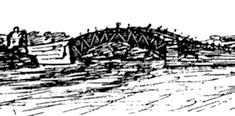
Th e December 14, 1793 issue of the New Hampshire Gazette listed the timber required for the arches. It included 1,535 pieces of pine timber from 15 feet to 50 feet in length, and ranging in size from 3 inches by 5 inches to 14 inches by 18 inches. Ninety-four of these pine timbers, intended for use in the wooden arch of the bridge, were to be 50 feet long and 14 inches x 18 inches with a 20-inch curve or sweep over the 50 feet. In other words he, wanted 50-foot long 14 x 18 pine timbers with a natural bend in them. Palmer designed his “great arch” with three sets of arches over a total width of 38 feet; each of these arches were diff erent than his previous bridges as he added a third intermediate member of the structure to carry the fl oor, rather than resting the fl oor on the bottom chord. In the words of a local historian, “the arch is composed of three tiers of girders, the lower one is sixteen feet from the chord, and twenty feet from the water at high tide. Th e second tier supports the planking on which the road passes, which is on a larger circle to facilitate the travelling. Th e upper tier answers the purpose of railing. Th ere are three sets of these girders, one on each side, and one in the middle of the bridge, which are so braced and framed together, as to make them whole strong and fi rm.” In other words, the lower
24'
16' 4'
40-50' Top Chord (Railing) Roadway
Lower Chord R = 450'± ~ Upper Chord R = 610'± ~
arch was the bottom chord of his truss, the upper arch was the top chord of his arch and the middle arch carried the fl oor to the truss. Th e span was almost 30% longer than his longest previous bridge. As with most wooden bridges of the time, the timbers would be cut and drilled to plan and erected off site to assure the proper fi t of all members. Th e trusses would then be dismantled and transported to the bridge site and re-erected on falsework. After all the connections were fi nished, the falsework would be dropped and the truss/arch would stand-alone. Work started on April 1, 1794 and the bridge was completed on November 25 of the same year. Palmer built massive falsework on which to build his trusses in the 50-foot deep and rapidly moving water. From a constructability
ADVERTISEMENT–For Advertiser Information, visit www.STRUCTUREmag.org standpoint, the falsework must have been as diffi cult to erect as the bridge. Th e main reason, other than depth of the water, was the 7-8 foot tidal range in the Bay. Palmer would later state, “he had, at the Piscataway Bridge, erected an arch of 244 feet; but he repeatedly declared that, whatever might be suggested by theorists, he would not advise, nor would he ever again attempt extending an arch, even to our distance, (Permanent Bridge) where such heavy transportation was constant proceeding.” Th e December 9, 1794 issue of the Portsmouth Gazette gave information on the bridge; its length was given as 2,362 feet, and width 38 feet. Th e article described the trestles as being built “on piles from fi fty-three to sixty-fi ve feet, driven into the bed of the river by ‘large hammers’ of oak timbers, braced and framed
on a new and improved plan.” The bridge construction used 3,000 tons of oak timber, 2,000 tons of pine, 80,000 feet of 4-inch plank; 20 tons of iron; and 8,000 tons of stone. Enos Whiting of Norwich, Connecticut is credited with superintending the pile work, and also with constructing “a draw for the passage of shipping, which moves across in a horizontal direction, instead of being raised on hinges, but it is feared this expected improvement will not answer the purpose.” Adams wrote “hundreds of people came long distances to cross and view the great enterprise that so auspiciously opened a new era in business. The Architect was Timothy Palmer of Newburyport, and the success of his work earned for him a great reputation. The entire bridge, [including the trestle spans and draw spans] cost $65,974.34, a large sum for those days.” It is clear that Palmer’s top chord on this bridge was only at railing height, and that the deck was close to the top chord and some distance (16 feet) above the bottom chord. This was the first time he changed his normal method of bracing the top chords overhead. He determined that a deeper truss was required for the longer span and that it became more difficult to have overhead cross braces, even if connected with ships knees, to provide sufficient lateral bracing. By having the deck near the top chord, it is possible to cross brace the trusses below the deck down to the lower chord. The bridge sparked a great deal of interest in the few international journals and books dealing with engineering subjects in the late 18th and early 19th century. The first written description of the bridge was in the Dictionary of Arts, Sciences and Miscellaneous Literature in its Supplement printed in Philadelphia in 1803: …a wooden bridge erected in North
America, in which this simple notion of Grubenhamm’s is mightily improved.
The span of the arch was said to exceed 250 feet, and its rise exceedingly small.
The description we got is very general, but sufficient, we think, to make it perfectly intelligible. In… are supposed to be three beams of the arch. They consist of logs of timber of small lengths, supposed of 10 or 12 feet, such as can be found of a curvature suited to its place in the arch without trimming it across the grain.
Each beam is double, consisting of two logs applied to each other side to side, and breaking joint, as the workmen term it.
They are kept together by wedges and keys driven through them at short intervals… Thomas Pope, in his 1811 A Treatise on Bridge Architecture, wrote that the “part which engages the attention of travelers is an arc nearly in the centre of the river, uniting two islands, over water forty-six feet deep. This stupendous arc of two hundred and fortyfour feet on the chord, is allowed to be a masterly piece of architecture, planned and built by the ingenious Mr. Timothy Palmer of Newburyport…” Since the original plans for the bridge have been lost in a fire at the company offices in Portsmouth, it is necessary to rely on the observations of travelers, and later writers, who were not engineers or builders but who had actually seen the bridge and crossed it, to understand the design and construction of the bridge and the impact it had on users. Timothy Dwight crossed the bridge in the fall of 1795, and described it as follows: …This structure stands in a region which gives it every advantage to make a striking impression on the mind…we came suddenly upon the bridge, an enormous structure, twenty-six hundred feet in length, of an interesting figure, finished with great beauty and elegance, new, white, and brilliant.
There are at this place two islands in the river; one, next to the southern shore, an oblong narrow rock: the other of sufficient extent for the site of house, garden, and some other enclosure…The whole scene had the appearance of enchantment, and in Arabia might not unnaturally have been attributed to the hand of a genie...Piscataqua bridge is formed of three sections; two of them horizontally, the third arched…The arch like the Haverhill Bridge [built in the following year] is triple, but no part of the work is overhead. The chord is 244 feet; and the versed sine, nine feet and ten inches. This arch is the largest in the United States, contains more than seventy tons of timber, and was framed with such exactness that not a single stick was taken out after it had been once put in its place. The whole length of planking is 2,244 feet. The abutments make up the remaining 356 feet and the island already mentioned…This is by far the most interesting structure of the kind which I have ever seen. Like the face in a well-contrived portrait, it is surrounded by such objects as leave the eye to rest on the principal one, and the mind to see but a single impression. Fletcher and Snow described the bridge as follows:
Its length was 244 feet, the rise was 27 feet 4 inches and the depth of framework of the arch, 18 feet 3 inches. There were three concentric ribs the middle one
carrying the floor of the bridge. The ribs were made from crooked timbers, so that the fibers were nearly in the direction of the curves, and they were connected by pieces of hard and incompressible wood, with wedges, driven between. The ribs were mortised to receive these connecting pieces and wedges, thus keeping an equal and parallel distance between them. Each rib was formed of two pieces, about 15 feet long, laid side by side in such a manner as to break joints. Their ends all abutted with square joints against each other, and were neither scarfed nor mortised. The two pieces of timber being held together by transverse keys and joints. All the timbers were admirably jointed and freely exposed to the action of the air. Any piece might be removed for replacement without injury to the remainder of the structure. It, primarily the deck portion, was rebuilt in 1803 when a lottery was held to cover the reconstruction. It was unusual that a wooden bridge would have to be rebuilt in only 7 years, but exisiting uncovered in a New Hampshire coastal environment could have accounted for significant decay of some of its members. The tolls were not sufficient to cover expenses, and the bridge was never a financial success. In 1818, Cyrus Frink, who had completed most of the earlier repairs, replaced the arch with “an entire new bridge, according to a wooden plan by him exhibited to the directors.” The reconstruction, including the new arch, was to be completed between June 4th and September 15th without obstructing or impeding the passengers. What his plan was, and how he replaced the main span while not cutting off traffic, is not clear. Whatever he did, it resulted in the removal of Palmer’s span. Frink’s bridge gave way on March 18, 1830 and, after being rebuilt, gave way again in 1854 and was not repaired. An ice jam on February 18, 1855 took the remainder of the bridge out. By that time, traffic had decreased significantly due to competition from the railroad that had opened between Boston and Portland, Maine, and the bridge was not rebuilt. This bridge was the most written about of any bridge in the country until Palmer’s Schuylkill River Permanent Bridge in 1805. Its 244-foot span was 84 feet longer in span than the Newburyport Bridge and incorporated an entirely unique framing plan, one that he, in part, was to use in his later bridges across the Schuylkill and Delaware Rivers.▪
Sutter Health Eden Medical Center

Structural Engineer’s Active Role in an IPD Project with Lean and BIM Components
By Mohammad Aliaari, Ph.D., S.E. and Edwin Najarian, S.E., P.E.
The Sutter Health Eden Medical Center (SHEMC) project in Castro Valley, California, set a new standard for structural engineers to play an active and signifi cant role in a successful Integrated Project Delivery (IPD) project, enhanced with Lean practices and Building Information Modeling (BIM) technologies. SHEMC is a new, state-of-the-art, 230,000 square foot replacement hospital with 130 acute care beds and a 36-bed universal care service. Th e vision of the project was to create
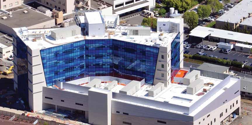
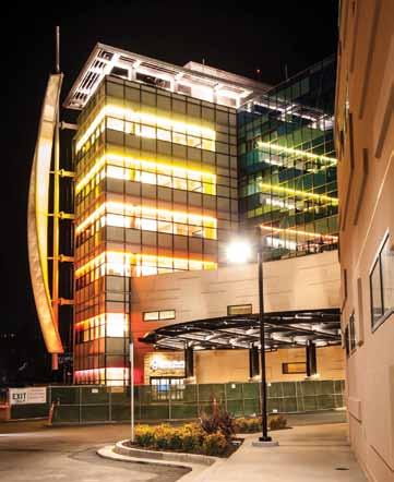
Figure 2: Sutter Health Eden Medical Center (SHEMC) Project. Courtesy of Sutter Health, Devenney Group, Christopher Skow Photography. Figure 1: Sutter Health Eden Medical Center (SHEMC) Project. Courtesy of Sutter Health, DPR Construction.
a landmark medical center that combines quality medical care, outstanding physicians and staff , and advanced technology to provide the best care for the community. Th e project consisted of a 7-story hospital building with a 4-story tower on top of a 3-story podium, a new central utilities plant and several new canopies (Figure 1 and 2). Th e design and construction cost was $230 million.
IPD Collaboration and Lean Practice
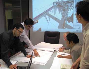
For the 1st time in the U.S., an 11-party IPD team including the owner, architect, structural engineer, design teams, general contractor and selected trade subcontractors, all co-signed an Integrated Form of Agreement (IFOA) contract, requiring them to work collaboratively, extensively use 3D BIM technologies, and implement lean practice, in a shared risk, shared reward environment, to design and deliver this hospital project within a 30% accelerated schedule and aggressive budget targets. Based on a study by the owner, there were potential high schedule and cost risks under a conventional design-bid-build process for this project. Some key strategies that were implemented to achieve the IPD objectives included: use of Value Stream Mapping to map the workfl ow; allocation of adequate early time and resources to plan the design process prior to design itself; bi-weekly 2-day team meetings (big room meetings) for design coordination; extensive use of BIM technologies with direct digital exchange capabilities (model based estimation, automated fabrication, scheduling, etc.); and, real time broad access to all project information through a web-based software. Extensive pool planning sessions were utilized during big room meetings for both design and construction phases throughout entire project duration. Arrangements were made for the inspector of record (IOR) of the project to be present in early project meetings. Th is allowed his voice and ideas to be heard ahead of time to minimizing potential comments and slowdowns during construction. Typically, IORs join the project long after approvals and at the start of construction.
Owner: Sutter Health Structural Engineer: TTG (TMAD Taylor & Gaines) Architect: Devenney Group General Contractor: DPR Construction
Other design teams and trade subcontractors
Structural System and Main Challenges
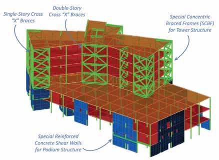
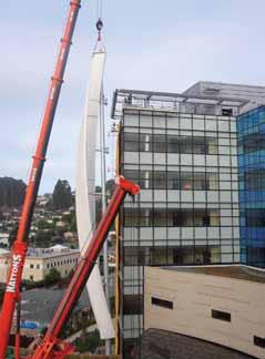
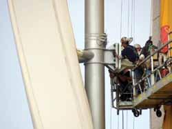
The project site is 0.5 miles from the active Hayward fault with Seismic Design Category F. Being an essential facility under California Office of Statewide Health Planning and Development (OSHPD) jurisdiction, results in a seismic importance factor of I=1.5. These factors led to the highest seismic design requirements in both California and the U.S. It was a challenging task for the structural engineer to design a structural Figure 3: Top: Isometric view of 3D structural analysis and design model. Courtesy of TTG system under the restricted requirements, meet the (TMAD Taylor & Gaines). inter-story drift limitations, and at the same time maintain the architectural intent and design. Several schemes were The foundation system consists of nearly 600, 60-foot deep, drilled investigated for an optimum system and, ultimately, a lateral friction cast-in-place piles (CIDH) with 75 ksi rebar. system combining Special Reinforced Concrete Shear Walls for The exterior of the building is a very complex skin interface the podium and Special Concentric Braced Frames (SCBF) for of glass curtain wall, precast CCAPP, precast GFRC, and metal the tower was selected. The tower floor plan is very irregularly panels. The analysis of interaction between the structure and skin shaped and lateral resisting brace frames are distributed mostly was a very challenging task. Design of geometrically complicated along the perimeter of the structure and around the elevator canopies and a 125-foot tall signature spire were among the other cores, where architectural design allowed. This provides a very challenges for the structural engineer. The building spire is designed robust and balanced distribution of the lateral system to control with all pipe elements and connected to five cantilevered beams the torsional and lateral movements (Figure 3). All braced frames with double end plate connections, which required very high fabare supported on shear walls in the podium level, with columns rication accuracy (Figure 4). There was an early aggressive project continuing to the foundation. The shear walls were designed using deadline to obtain a partial fund contingent on OSHPD approval concrete compressive strength of 7,000 psi. TTG, the structural of the structural design package, which put tremendous pressure engineer, performed extensive soil-structure interaction model- on the structural engineering team. The structural engineer had ing and analyses to provide a justified and lighter design for this to complete the structural design and obtain approval in advance, hospital project. A study by the project geotechnical consultant while the other design disciplines were still in early design phases provided required information for soil modeling and parameters. with target approval dates of at least one year ahead. Figure 4: Photos of installation of signature 125-foot tall spire element with double end plate connections. Courtesy of Sutter Health, DPR Construction.
Incremental Review and Structural Plan Checking Process
This project is one of the earliest projects in California using OSHPD’s incremental phase review process to accelerate the permitting process. The project was submitted in five different increments, including; primary structural system, site, building exterior, building interior, and medical equipment. Each increment consisted of several segments or phases. The design team had to completely transform from the traditional design workflow of schematic design (SD), design development (DD), and detailed construction documents (CD), and create a new workflow and process to allow the start of early construction along with a simultaneous design progress and intense 3D model-based design coordination. A 3rd party structural engineering firm was assigned by OSHPD for structural plan checking of the project. The structural engineer worked very closely with the
plan checking team through a detailed and delicate process, in which the review comments and responses were communicated in a weekly manner until all the comments were resolved and approval for the structural package was obtained on time.
3D Review of Structural Shop Drawings
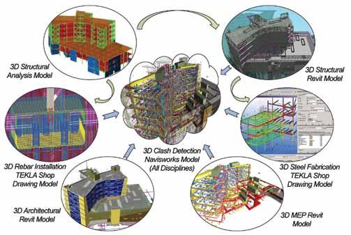
This project is one of the 1st projects where the structural engineer reviewed shop drawings in full 3D format. The 3D review of structural steel shop drawings was conducted through direct exchange of TEKLA models between the structural engineer and the steel contractor in 22 different segments. The structural engineer worked with Herrick, the steel fabricator, to customize TEKLA for a more streamlined review process. At any point in time, the structural engineer was working on the review of new segments while back checking prior segments, sequenFigure 5: Full 3D BIM-Based design, and construction modeling and coordination. Courtesy of TTG (TMAD Taylor & Gaines). tially. In addition, rebar installation shop drawings were also generated in 3D TEKLA models and reviewed in 8 different concrete pours. This allowed for a detailed constructability review by the structural engineer, In Conclusion general contractor, and rebar detailer. The 3D review process eliminated traditional methods of providing and mailing thousands of hard prints, resulting in savings in both project cost and in time. SHEMC was the 1st full IPD, 11-Party IFOA project in the US and also one of the earliest OSHPD incrementally reviewed projects. The project was very successful. TTG, the structural engineer, played a significant role, utilizing advanced and innovative technologies to
BIM-Based Design and Clash Detection overcome challenges and contribute to the success of the project: Extensive virtual design and building modeling efforts were utilized. Various 3D design models, along with 3D shop drawings models, were reviewed and clashed using Navisworks in a multi-disciplinary fashion (Figure 5). This process allowed the structural engineer and contractors to better understand the contact between the various structural and non-structural elements, and permitted resolving issues and conflicts ahead of time (Figure 6 ). Typically, these types of issues would not be identified and resolved until progress of construction, resulting in costly field repairs and delays. • • • • • All of the IPD goals were met or exceeded. Project delivered ahead of schedule, even with 30% fast track schedule. Project delivered on-budget, even with aggressive budget targets. The structural engineer produced fully coordinated and constructible drawings and 3D models. Steel delivered 6 months ahead of schedule with over $1 million in savings, returned to owner by steel contractor due to active collaboration between the structural engineer and steel contractor and IPD team in review of 3D shop drawing. • Construction change orders & RFIs for structure were under 15% of estimates for comparable hospital projects in California. • The project has won numerous design and construction awards. • The project has been twice on cover page of Engineering News-Record (ENR) (September 2011 and May 2009 issues).▪
Mohammad Aliaari, Ph.D, S.E., is a Senior Associate, Structural Project Manager at TTG Office in Pasadena, CA. He can be reached at maliaari@ttgcorp.com. Edwin Najarian, S.E., P.E., is a Principal, Structural Vice President at TTG Office in Pasadena, CA. He can be reached at enajarian@ttgcorp.com.
Padma Bridge
Design for Severe Earthquake and Deep Riverbed Scour
By Robin Sham, Ph.D., C.Eng, FICE
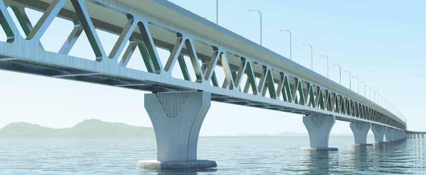
Padma Bridge – a 6.15km long, combined rail-road river crossing.
One of the greatest challenges to long-span bridge engineering is the forces of nature. Recent catastrophic events around the world reinforce the fact that nature can be destructive to infrastructure. At the Padma Bridge site in Bangladesh, AECOM used state-of-the-art technology and innovative disaster prevention and mitigation solutions to tackle some severe challenges. At 6.15 kilometers (3.8 miles) in length, the Padma Bridge is a landmark structure and one of the longest river crossings in the world. The Padma River is the third largest river in the world, and has the largest volume of sediment transport. During monsoon seasons, the Padma River becomes fast flowing and is susceptible to deep scour, requiring deep-pile foundations for bridge stability. The Padma Bridge site is also in an area of considerable seismic activity, resulting in significant earthquake forces being exerted on the bridge. This combination, together with other forces of nature, posed a unique challenge. The multipurpose Padma Bridge detailed design project has been successfully completed. AECOM developed alternative concrete deck forms, including an extradosed concrete truss bridge, a concrete girder bridge and a steel truss bridge. In all cases, a two-level structure was chosen, having significant advantages over a single level structure. These included segregated highway and railway envelopes to offer enhanced safety, improved operation, inspection, maintenance, and emergency evacuation procedures, as well as efficient provisions for utilities. With the railway in the lower deck, the structural depth beneath the railway is reduced, allowing the lengths of the railway approach viaducts for tie-in at the north and south banks to be minimized. With a two-level structure the construction cost is reduced, making the structure more efficient. Analytical models were developed for each of the bridge forms to determine member sizes and, in particular, the weight of the superstructure. The steel truss bridge was found to be the most efficient with the lightest deck. Further details of this option were developed to determine the optimum span length. Total deck weight and foundation loads were compared for span lengths of 120 meters, 150 meters and 180 meters (394 feet, 492 feet and 591 feet, respectively). From this data, a construction cost was estimated for each span length with the optimum span being 150 meters. In conclusion, the most economic and appropriate form for the bridge was found to be the steel truss bridge with a concrete top slab acting compositely. The multipurpose bridge also has many utilities built into it, including a gas pipeline, telecommunications and a high-voltage power transmission line. Additionally, it has emergency access points in order to facilitate evacuation of a train on the lower deck. A detailed study of seismic hazard at the site was performed to determine suitable seismic parameters for use in the design. Two levels of seismic hazard were adopted: Operating Level Earthquake and Contingency Level Earthquake. Operating Level Earthquake has a return period of 100 years with a 65 percent probability of being exceeded during that period. Contingency Level Earthquake has a return period of 475 years with a 20 percent probability of being exceeded during a 100-year bridge life period. Any damage sustained from such an earthquake would be easily detectable and capable of repair without demolition or component replacement. In conjunction with these investigations, AECOM carried out further analysis to determine the optimum foundation design, and two pile types were investigated; large diameter (3 meter; 10 feet) raking steel tubular piles and large diameter cast-in-situ concrete bored piles. Raking piles were more efficient in resisting lateral loads resulting from earthquake motions. This type of load is resisted as axial force in the steel piles, while the lateral load is resisted by the flexural capacity of the piles for the concrete bored piles. The very large bending moments generated by a seismic event dictated that insufficient flexural capacity could be created by reinforcement alone, and a permanent steel casing would be
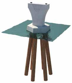
Raking steel tubular piles are very effective in withstanding large lateral forces. Some 60 meters (197 feet) of pile is unsupported due to riverbed scour.
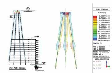
A structure-free field soil interaction model. required to enhance the capacity down to 10 meters (33 feet) below the riverbed level, which for a 100-year scour event would be -61m PWD. It would also be necessary to have more than fifteen 3-meter (10 feet) diameter vertical concrete piles, compared to eight raking steel tubular piles. The large number of piles increased the weight of the pile cap and also the local scour. All of these factors had an adverse effect on the cost and constructability of the foundations, therefore the preferred solution was recommended as being the raking steel tubular piles. The behavior of the bridge is complex due to its height, which is 120 meters (394 feet) when the effects of scour are taken into consideration, and the large mass of the superstructure, pile caps and piles. A three-dimensional non-linear time history dynamic analysis, using a modified Penzien model, was adopted. It was divided into two parts, the structure and the free field soil. The interactions between the structure and the free field were simulated by lateral spring links. In order to determine the equivalent shear modulus and effective damping ratio between each layer of the soil, free field analysis was carried out beforehand using the Shake analysis program. Subsequently, a threedimensional dynamic analysis was carried out using the equivalent shear modulus and effective damping as input data. Ground motions were applied to the model to simulate the earthquake case, and loads were generated in the piles and substructure accordingly. Although other load combinations were considered, such as ship impact and wind, these effects were not found to be critical for the substructure, and the seismic load combination dictated the design. A further model was developed to investigate the global behavior of the bridge. The bridge is divided into six span modules, each span 150 meters (492 feet) long, so the global analysis model examined an individual six span module and applied different levels of scour at each pier. A scour hole may form around an individual pier, or around two or more piers. The global model looked at various combinations in order to determine the critical axial, shear and bending loads on the foundations of any particular pier.
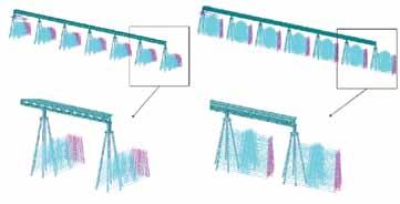
A three-dimensional global model for a 6-span bridge module.
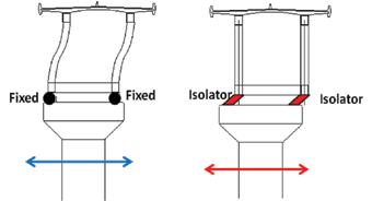
Initial studies of the bridge were based on the deck being supported by traditional sliding bearings, with the point of fixity being the central pier of the six-span module. To avoid the fixed pier being heavily loaded during a seismic event by a longitudinal translation, shock transmission units were proposed at the free piers to ensure even load distribution between the piers. But under this system, the loads applied to the piers were still large; therefore, as part of the value engineering process, AECOM considered alternative forms of articulation. The original seismic design strategy was to dissipate seismic energy through plastic hinges at the bottom of the piers. Further design optimization identified the benefits of seismic isolation, which allows the structure to behave elastically without damage. The application of seismic isolation has reduced the number of piles, the size of the pile caps and the size of the steel superstructure, resulting in a more cost effective design. Seismic isolation bearings have been used worldwide to mitigate seismic response by isolating structures from seismic input. They can accommodate thermal movements with minimum resistance, but will engage under seismic excitations. In this strategy, all primary structural members remain elastic without any damage or plastic hinging. Isolation bearings contain three key elements: one to provide rigidity under service loads and lateral flexibility beyond service loads, one to provide self-centering capability, and one to provide energy dissipation. These key elements have to be properly designed and fine-tuned to achieve optimal seismic behavior. Analyses indicate that seismic forces can be greatly reduced by replacing conventional pot bearings with isolation bearings. Friction pendulum bearings utilize the characteristics of a pendulum to lengthen the natural period of the isolated structure so as to reduce the input of earthquake forces. The damping effect due to the sliding mechanism also helps mitigate earthquake response. Since earthquake induced displacements occur primarily in the bearings, lateral loads and shaking movements transmitted to the structure are greatly reduced. The reduced seismic loading generated at the top of the bridge piers significantly reduces pile loads. With the conventional scheme of bearings and shock-transmission units, eight raking steel piles were required for each pier; with seismic isolation this was reduced to six, leading to a savings in foundation costs of more than 20 percent. AECOM then further developed the design with the inclusion of seismic isolation. The impact of the seismic isolation scheme is not limited to the substructure; the reduced seismic loading leads to reduction in section sizes for truss members, with an overall saving in truss steelwork of greater than 6 percent.▪
Robin Sham, Ph.D., C.Eng, FICE, is Global Long Span and Specialty Bridges Director of AECOM. In 2011, he was conferred the highly prestigious Fellowship of the City and Guilds of London Institute for his “outstanding contribution to the field of civil engineering”. Dr. Sham may be reached at robin.sham@aecom.com.
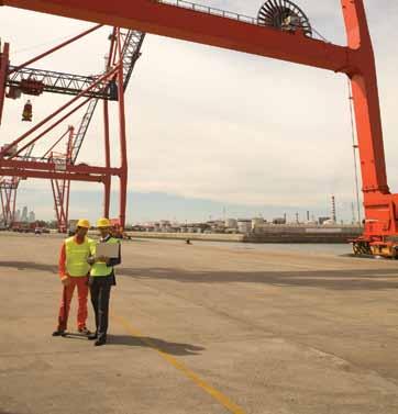
Mass Transit at Phoenix Airport
By David A. Burrows, P.E., LEED AP BD+C and John A. Lobo, P.E., S.E.
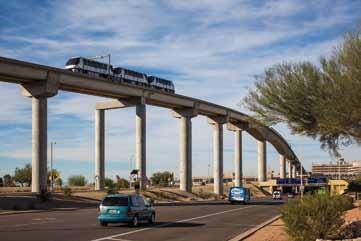
PHX Sky Train headed east over the Taxiway R Crossing, Terminal 4 and the control tower in the background. Courtesy of Bob Perzel.
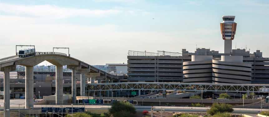
On April 8, 2013, Phoenix Sky Harbor International Airport opened the first stage of the PHX Sky Train™, a 5-mile long automated transit system exclusively serving the Airport. Expected to carry 2.5 million passengers a year, the system provides a dedicated, streamlined, safe, convenient, and more sustainable transportation link between airport terminals, parking lots, rental car center and regional lightrail transit facilities, and reduces congestion around the airport terminals. This is no small feat given that Sky Harbor is one of the ten busiest airports in the country. Known as one of the largest economic engines in the state of Arizona, Sky Harbor currently serves over 40 million people a year and has grown steadily throughout its 75 year history. Since the development of its newest terminal in the late 1980s, the Airport has contemplated building a transit system to deal with traffic congestion due to increasing passenger demand and aging ground transportation infrastructure. Without the Sky Train, projections show that quality of service and future Airport growth would be crippled by gridlock on the Airport’s roadways. Planning efforts resulted in a 5-mile long corridor for the Sky Train in three stages to spread overall funding requirements. Currently operating, Stage 1 consists of approximately 2 miles of guideway, of
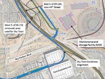
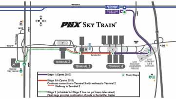
Figure 1: PHX Sky Train route map. Courtesy of Phoenix Aviation Department.
which over 1.5 miles is elevated, to connect three stations: a Metro light-rail stop; a major airport parking facility; and Terminal 4, the largest airport terminal. Stage 1A, which is now under construction, builds a new station at Terminal 3, approximately ¾ mile of guideway and a walkway to connect the Stage 1 facilities and Terminal 2. The final stage is in conceptual design and will provide future connections to the rental car center and another major airport parking lot (Figure 1).
Transit System Planning
Constructing a dedicated transit system within an operating airport is costly and will unavoidably impact existing facilities and operations. However, the Phoenix Aviation Department determined that long-term benefits outweighed the short-term cost and potential disruptions. Projections for Sky Harbor showed that an automated transit system would be the best way to increase landside capacity and avoid restricting future airport growth. To maximize benefits, planning considered long-term development of the Airport, opportunities for transit oriented development, strategies to maximize ridership on the system, and repurposing an adjacent underutilized freeway. • Station siting – providing connections at the airport terminals, parking facilities, rental car center and the regional light rail system, stations are located to serve passengers as well as airport and airline employees and other support staff.
When fully operational, the Sky Train will eliminate existing
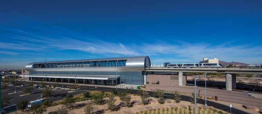
44th Street Station. Courtesy of Bob Perzel.
airport bus operations. Stations are sited and programmed to accommodate future parking garages, support facilities and potential private development to increase ridership. • Accommodation for future stations – segments along the alignment are designed to accommodate future stations for additional airport parking and terminal facilities needed for long-term growth. • Provide drop-off/pick-up away from terminal core areas – to relieve congested terminal curbs, designated nonterminal stations will accommodate buses, vans, shuttles, passenger vehicles, etc. This will create convenient passenger drop-off and pick-up areas that are a short Sky Train ride away from terminals. • Repurpose an existing freeway – without a good connection to the surrounding regional freeway system, a section of freeway located just east of the Airport, SR 153, had historically been underutilized. The project uses a portion of the corridor to carry the Train at-grade, creating a very cost effective solution to what would otherwise have been a costly below grade alignment through a runway protection zone. The remainder of SR 153 was modified to a typical city street where it still has ample capacity to carry traffic flows (Figure 2). This freeway corridor reconfiguration is estimated to have saved the project approximately $30,000,000.
Planning to Build in an Operating Airport
Sky Train infrastructure design required careful consideration of construction impacts on airport operations and facilities, as construction requirements drove many key design decisions. An integrated design and construction approach was used to help ensure that the project was built on-time and on-budget. At the 30% design level, a Construction Manager at Risk (CMAR) contractor was brought onto the team. The use of CMAR allowed early confirmation of construction schedule and budget, value engineering to be integrated into design, constructability issues and operational impacts to be mitigated during the design phase, and design tailored to the contractor’s preferred construction approach. A fast-track delivery of construction documents was necessary to minimize overall project schedule and risk associated with inflation and fluctuating material costs. In order to accomplish this, design and construction schedules overlapped by 2 years in an overall construction schedule of 3.5 years; and, to allow design to stay just ahead of construction, 31 separate design packages were issued. Building Information Modeling (BIM) was used by all design disciplines for vertical structures, and shared with the contractor to avoid conflicts and quickly resolve those that did occur. The single most fundamental element to mitigating construction impacts to all airport patrons, tenants, airlines, and operations was developing and communicating a well planned construction plan, gaining buy-in by stakeholders, and executing it as scheduled. It was essential that the airport continue to provide for the needs of airport users even through the most demanding construction operations. Therefore, a thorough outreach to multiple stakeholders was critically important. Key stakeholders extensively involved in the project were: Airport Operations, Airport Facilities & Services, the Airlines, Federal Aviation Administration, Valley METRO Rail and the Union Pacific Railroad. Some of the challenges mitigated by advanced planning and stakeholder communication included: • Restricting heavy construction activities around Terminal 4 to nights in order to minimize effects of noise, dust and congestion from construction traffic on passengers.
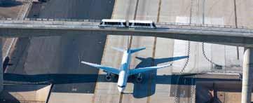
A US Airways jet passes beneath the Taxiway R Crossing with the PHX Sky Train overhead. Courtesy of City of Phoenix Aviation Department.
• Keeping the pedestrian bridge between concourses open while constructing the Terminal 4 Station and guideway directly above them. • Minimizing the number of concourse gates that were closed during any given period. The Sky Train team worked closely with the affected airlines to minimize gate closures and scheduled work so that closures could be staggered, especially during peak travel seasons. • One of the security checkpoints directly below the Terminal 4 Station was scheduled for expansion shortly before Sky
Train construction. By working closely with the Airport and
Checkpoint design team, the support columns of the Station in the area were constructed during the checkpoint widening work, thereby eliminating a future disruption. • Sky Train’s pedestrian bridge link to the Valley Metro Light
Rail system crosses above the Light Rail’s overhead catenary power lines. To avoid future disruption of Light Rail service, completion of the pedestrian bridge had to be advanced ahead of the December 2008 start of Metro Light Rail operations, several months ahead of breaking ground on Sky Train construction.
Creating a LEED Certified System
In January, 2013, the PHX Sky Train facilities achieved Gold certification from the U.S. Green Building Council (USGBC) under the Leadership in Energy and Environmental Design (LEED) for New Construction Version 2.2. Supporting LEED’s priority to reduce greenhouse gas emissions, operation of the Sky Train alone will relieve terminal roadway and curb congestion and will result in approximately 20,000 fewer vehicles per day at Sky Harbor, thereby reducing CO2 emissions by nearly 6,000 tons annually and ensuring that the airport’s
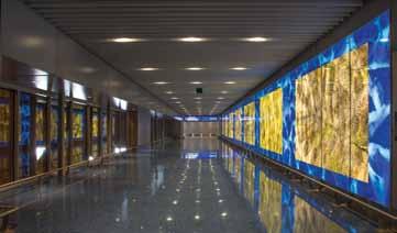
Figure 3: LEED scorecard for PHX Sky Train Stage 1. Source: U.S. Green Building Council. Interior of the bridge over Sky Harbor Blvd leading to the Terminal 4 Station. Courtesy of Bob Perzel.
LEED Facts
for New Construction (v2.2)
Certification awarded Jan 2013
Gold
Sustainable sites Water efficiency Energy & atmosphere Material & resources Indoor environmental quality Innovation
44
5/14 3/5 10/17 7/13 14/15 5/5 roadways flow freely. Efficiencies that were built into the Sky Train project, as documented by the LEED process, are expected to save the City over $10 million dollars in the first 20 years of operation. Initially, only the Sky Train stations were planned to be LEED certified. However, during the design process, a campus approach, whereby stations and guideway would be rated together, was chosen as the best option. This change was motivated primarily because the East Economy Lot station was changed from an enclosed to an open-air structure. While the latter consumes less energy, the baseline against which energy reduction would be measured was reset to an open-air structure. Although the first transportation project to be evaluated using a campus approach, it allowed credits to be computed as an aggregate for the guideway and stations, rather than by each individual station. The campus approach proved to be advantageous, allowing a score of 44 out of 69 possible credits, as seen in the details of Figure 3.
Stage 1 Grand Opening
With about 300 elected officials, business leaders and other invited guests in attendance, on April 8th of this year, the PHX Sky Train made its debut run from the 44th Street Station to Terminal 4. The automated, electric train’s smooth and seemingly effortless ride stands in sharp contrast to the monumental effort that went into building it. Constructing nearly two miles of guideway at one of the busiest airports in the country without disrupting flights, halting traffic, or going over budget, is a huge achievement for the City, the contractors and the design professionals involved. Challenges such as making the world’s first crossing of an active taxiway, fitting the Terminal 4 Station around an existing pedestrian bridge and concourses, and weaving a narrow path between two multistory parking garages, were overcome with collaboration, cooperation and perseverance. The end result is that the Sky Train has transformed the Airport’s landside transportation system. Growing from a two terminal airfield serving 3 million people annually just four decades ago to a three terminal international airport serving 40 million passengers last year, completion of the Sky Train will position Sky Harbor to continue providing highquality service well into the future.▪
David A. Burrows, P.E., LEED AP BD+C, is a senior structural engineer at Gannett Fleming, Phoenix, Arizona. He was the lead engineer for the design of the Taxiway R crossing. David can be reached at dburrows@gfnet.com. John A. Lobo, P.E., S.E., is a bridge engineer at Gannett Fleming, Phoenix, Arizona. He was a member of the Sky Train fixed facilities design team for 10 years. John can be reached at jlobo@gfnet.com.
SoNo Ice House
Time for a Change

By Bruce D. Richardson, P.E., Nils V. Ericson III, P.E., LEED AP and Chris T. O’Brien, P.E.
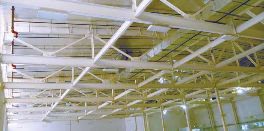
Figure 2: Clear-span trusses.
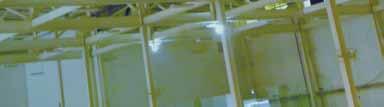
The renovation of an obsolete manufacturing facility into a state-of-the-art ice hockey development center presented challenges that required creativity, teamwork, and an owner committed to following a lifelong dream in order to keep the project on schedule and under budget. Ryan Hughes, the owner and operator of North American Hockey School and manager of North American Rink Management, had the vision to utilize the former manufacturing building’s high bay clearance and wide open interior spaces to create a state-of-the-art hockey facility that featured two indoor hockey rinks. He needed to get the project started quickly and be in operation in time for the start of the season for the Connecticut Oilers of the Empire Junior Hockey League, the rst local hockey team in Norwalk, CT in over 50 years. Ryan enlisted the help of Claris Construction Inc., a Design-Build contractor from Newtown, CT and e Di Salvo Ericson Group, Structural Engineers, Inc. from Ridge eld, CT. After the initial walk-through of the cavernous space in July 2011, it was apparent that the building had some obstacles to overcome before conversion into a hockey facility would be completed. e one-story industrial building had served as a manufacturing plant for Nash Engineering from the time it was constructed in the 1960s until they moved out in 1995. e building’s con guration was well-suited for a manufacturing plant; it included tall interior clearance, 45 feet high at the roof peak, and widely spaced interior columns. e roof framing system consisted of sloping steel rafters supporting zee-purlins. Despite the tall clearance and wide column spacing, many of the interior columns would con ict with the layout of the hockey rinks and would need to be removed. In addition, a temporary sound studio had just moved into a portion of the building to begin the lming of a major motion picture, and the noise sensitive lming operations would prevent any construction activity on the site for several months. Using historical documents of the original construction, e Di Salvo Ericson Group modeled the existing roof framing system and developed a method of removing the interior columns that con icted with the hockey rink locations. e column removal would be accomplished by creating trusses out of the existing sloping steel rafters by introducing new horizontal steel bottom chords and sloping steel web members between the rafter ends. e new truss con guration would clear span over the new hockey rink locations and be supported on new steel columns and footings at each end. Furthermore, the new column-truss frame would be rigidly connected to upgrade the renovated facility to current Connecticut State Building Code wind and seismic requirements. e upper portion of the existing steel columns would be incorporated into the new truss con guration and, after the construction of the trusses was completed, the lower portion of the columns would be removed (Figure 1). Claris Construction, Inc. prepared a nal layout of the new hockey facility within the existing building that indicated the removal or relocation of twelve (12) interior columns. Also, a new two level mezzanine would be required to provide additional space for a training gym, locker rooms, and a snack bar. Prior to the nal design and fabrication of the clear span trusses, eld measurements and documentation of the existing steel rafters and columns were required to provide an accurate basis for the nal design model and for the fabrication drawings. is responsibility was assumed by the steel fabricator, Engineered Building Products, of Bloom eld, CT, and was undertaken immediately following the completion of the motion picture lming and the removal of the sound stage sets. Interestingly, the results
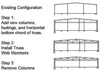
of the eld measurements showed that the existing steel framing was out of plumb by a few inches at the peak of the roof, parallel to the ridge, and required that the new columns at the ends of the trussed rafters be o set from the existing columns on the exterior wall by the same amount. e structural engineers used the eld measurements to prepare a nal design model with RAM Structural System and Visual Analysis to analyze and design the new structural steel elements of the clear-span roof trusses. e nal design included the analysis and strengthening of the existing sloping steel rafters to support the additional compression force that would be introduced after the truss construction was completed and the columns were removed. e eld measurements were also used for the preparation of the structural details of the new truss connections, and allowed for including provisions to accommodate the eld variations in the location of the steel members and for the out-of-plumb steel framing. e unique approach to the roof framing alterations allowed the building to remain enclosed and intact during the renovation, and the new horizontal bottom chord of the trusses allowed ample headroom for the hockey activities. In addition, by leaving the existing columns in place until after the construction of the trusses was completed, the requirement to temporarily shore the building was eliminated, allowing unrestricted access to the work area so that the installation of the footings at the new column locations could start immediately. is feature turned out to be extremely bene cial to the project schedule. During the early part of the project, as the excavations for the new column footings began, several buried foundations were uncovered that were not anticipated and that were not re ected in the historical documents. As a result, the design and construction of many of the new foundations was delayed in order to address the unique condition of these speci c footing locations. e project completion would have been delayed signi cantly if the new foundation work had not bene ted from the early start. Once the foundations were completed, the steel roof truss framing was installed relatively quickly and the tight project schedule was maintained while transforming the forty year old industrial building into a modern sports facility (Figure 2). Claris Construction, Inc. and e Di Salvo Ericson Group approached the project with the understanding that the solution to the column removal needed to address the short time schedule, the limited access to the space at the start of the schedule, and the need to keep the project within budget. e unique solution to create trusses out of the existing sloping rafters was a simple idea that made maximum re-use of the existing structure, and took advantage of the existing high bay clearance and the relatively low headroom required for hockey. e execution of the solution was complicated by the need to implement the work in a short time period while adapting to the various geometries and hidden surprises provided by the existing conditions.▪
Bruce D. Richardson, P.E., is a Principal with e Di Salvo Ericson Group in Ridge eld, CT. Bruce may be reached at bruce@tdeg.com. Nils V. Ericson III, P.E., LEED AP, is a Project Manager with e Di Salvo Ericson Group in Ridge eld, CT. Nils may be reached at nils@tdeg.com. Chris T. O’Brien, P.E., is a Senior Project Engineer with e Di Salvo Ericson Group in Ridge eld, CT. Chris may be reached at chris@tdeg.com.
e project was awarded a 2013 ACEC/CT Engineering Excellence Award.
ADVERTISEMENT–For Advertiser Information, visit www.STRUCTUREmag.org