22 minute read
STRUCTURAL DESIGN
design issues for structural engineers T he intent of this 3-part series is to expand the engineer’s understanding of the realities and opportunities in fatigue and fracture design. After reading this segment, the reader may have more questions than answers. Tis is not because the reader will not learn anything, but because they will better know the questions they should be asking.
Have Crack? What’s Next?
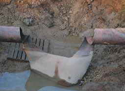
Have you ever had a crack in a structure or been called on to evaluate one? It can be rather unsettling. Cracks like the one in Figure 1 are pretty easy. We replace the segment of pipe. However, what if you have a crack like the one in Figure 2? Alternatively, the UT inspector tells you there is a crack inside a key portion of your structure that you cannot even see. Under these circumstances, the solutions become less obvious and more difcult. Complicating matters is the fact that there is nothing in the codes that guides the General Principles of Fatigue and Fracture engineer in evaluating cracks, leaving a big hole in the engineer’s ability to assess them and provide recommendations for Part 1 repair. Fortunately, there are ways to evaluate these challenges, which will be discussed in the By Paul W. McMullin, S.E., Ph.D. next two articles in this series.
Figure 1. Rupture in a gas pipeline.
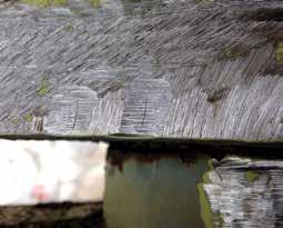
Figure 2. Crack in a steel truss.
Fantasy vs. Reality
Paul McMullin is a founding partner at Ingenium Design in Salt Lake City. He is an Adjunct professor and the lead editor of the Architect’s Guidebooks to Structures series. Paul can be reached at Paulm@ingeniumdesign.us.
It’s Complicated – and that’s OK
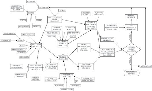
Embrace the complicated nature of cracks. Te variables that infuence fatigue and fracture behavior are truly legion. Figure 3 shows numerous inputs into fatigue and fracture design. It is certainly not complete, but it is a good start. Te greatest disservice we can do in our approach to fatigue and fracture design is to oversimplify things. Crack design is full of oversimplifcations. Why? It makes the design easier – initially. Who would not like that? In the real world, the problem and solution are much more complex. Oversimplifying the problem results in the engineer missing important variables that afect performance.
By looking at the way engineer’s talk about fatigue and fracture, we see where fantasy distorts reality. Te fatigue constant, Cf , is a common fxture in the fatigue design tables of the American Institute of Steel Construction (AISC), the American Association of State Highway and Transportation Ofcials (AASHTO) and the American Railway Engineering and Maintenance-of-Way Association (AREMA). However, it varies in each table. How can a constant have many diferent values? Te mere fact we call Cf a constant shows we have room for improvement in the way we think about fatigue. Two examples are illustrative of the fantasy in fatigue design. Let’s take a look at the S-N curve and the assumed crack in an eyebar. S-N Curve Te textbook stress-number of cycles (S-N) curve is nice and smooth and comes complete with a threshold for steels. However, when we look at the test data represented in Figure 4, we see scatter – lots of it. Fantasy is a simple curve; if we keep our stresses low enough, we do not ever have to worry about cracks. Reality tells us there will be outliers that lead to cracks. Eyebar Te assumed crack location in an eyebar is at the pin, perpendicular to the bar length, illustrated in Figure 5. Tis makes a lot of sense and is a great place to start. However, if we only looked for cracks at the assumed location, we might miss all the other cracks. Reality shows us cracks do not just occur where we expect them to. Why? Let’s get into that.
Why Complicated?
So why is it so complicated? Mother Nature. Seriously. Materials are not perfect, environments are not benign, and loads are never what we think. More specifcally, the following profoundly afect crack formation, growth, and critical size: • Size • Location • Detailing • Grain Structure • Residual Stress • Corrosion • Load spectrum Tese parameters are where many of the outliers originate. Laboratory testing simply cannot
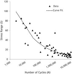
Figure 4. Scatter in fatigue data.
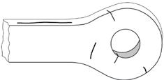
Figure 5. Assumed and actual crack locations in an eyebar.
ADVERTISEMENT–For Advertiser Information, visit www.STRUCTUREmag.org


US Patent 6213679; other patents pending


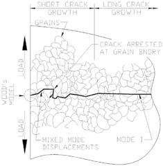
Figure 6. Crack growth phases.
pick up all the variables that a structure will experience. Tis is unsettling if all we have available is a chart that tells us our structure will live forever if our stress is low enough. So what should the design engineer do? First, come to terms with the reality that cracks are complicated. As the engineer embraces all the parameters, it will become clear what is important and what needs additional attention. Second, use improved tools such as fracture mechanics to quantify the problem better. Tird, use realistic material testing. Fourth, inspect. At some point, get out in the feld and look at the problem. Observing the problem frst-hand is the only way to know what is going on. Finally, embrace the vast array of knowledge that is available. To this point, Pellini, while at the Naval Research Labs stated:
In summary, the present trends in fracture research emphasize an ever-increasing sophistication in the treatment of the problem – building upon rather than eliminating past knowledge. Te great variety of fracture research evolves from the need for attention to widely diferent problems which have special features.
Terefore, the engineer should not expect that fracture-safe design should ultimately evolve to a single generalized procedure, but rather to a variety of procedures that overlap and integrate into a coherent pattern. (Pellini 1969, p. 87) More than a nice quote – it is wisdom for the ages.
Crack Growth Basics
Crack Growth Phases Getting into some specifcs, consider the following four stages of crack growth: nucleation, short and long growth, and fnal instability. Te frst three phases are shown in Figure 6. Te nucleation phase is the period required for a crack to form. Next, the short crack path depends heavily on grain structure, and often described as “tortuous”. Te long crack phase is smoother, larger, and less infuenced by grain structure. Final instability is often fast fracture, with the crack moving at the speed of sound in the material. Crack Modes Tere are three modes of crack loading: opening (Mode I), sliding (Mode II), and tearing (Mode III). In Mode I, cracking is characterized by stresses and displacements normal to the crack surfaces. In-plane shearing stresses with associated crack displacements in the plane of the crack, and perpendicular to the crack leading edge, produce Mode II cracking. Mode III cracking is caused by out-of-plane shear with displacements also in the plane of the crack, but parallel to the crack front. Crack Growth Mechanisms While fracture mechanics is interested in dealing with the critical crack size and how fast a crack will reach this size, it tells us nothing about how the crack originated. Without understanding how the crack formed, one can only superfcially deal with the crack. However, when the processes of cracking (the physics of failure) are understood, the crack can be treated in a holistic manner. Tis results in a safer, more reliable structure. A broad range of mechanisms cause cracks and infuence a crack’s potential propagation and propagation rate. Figure 3 lists many of the factors that afect both crack nucleation and growth. As seen from the table, the causes of cracks and infuencing factors on propagation are intermingled. Focusing on one variable, as is so often the case with stress, and not considering other factors will likely result in a design that is unconservative, possibly by orders of magnitude.
Constraint
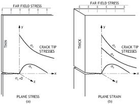
direction of applied stress) due to Poisson’s efect, illustrated in Figure 7. Triaxial stress states reduce the principal shear stresses in materials. Tis, in turn, diminishes plastic deformation, which occurs on planes of principle shear stress due to slip. To come full circle, the reduction in a materials ability to plastically deform reduces its toughness, or ability to absorb fracture energy.
Fracture Toughness
Toughness is to the boxer as strength is to the weightlifter. Toughness is a measure of the amount of abuse a material can take. More technically, fracture toughness measures crack resistance. Toughness Trends Fracture toughness and all structural properties are infuenced by size. As size increases, toughness – and strength, stifness, and stability – decrease, as shown in Figure 8. As we move from a test specimen to component test to full-scale performance, there is a general trend of decreasing properties. Unique to fracture toughness, as the material gets thicker, the toughness decreases. After a certain point, the toughness remains the same – known as the plane strain fracture toughness. Toughness is also highly infuenced by temperature. Figure 9 shows the transition curves for a Charpy and Dynamic Tear Test. As temperature decreases, so does fracture toughness. Note how the test type changes the location of the curve. Te curve to the right is a 1-inch thick specimen, while the Charpy curve is based on the standard one-half inch thick specimen. If the material was ½-inch thick and relied on the Charpy test, we would grossly miss the actual transition temperature. Tis was the case in the Liberty Ship failures during World War II. Finally, strain rate afects fracture toughness. As the strain rate increases, the toughness decreases. It is worth considering this for impact type loads.
We hear from seasoned engineers to avoid over-welding joints. Why? It certainly has an economic and environmental impact, but, more importantly, it reduces constraint. Reduced constraint increases toughness and energy absorption. Constraint refers to the materials inability to deform because the surrounding material restrains it. When a material is constrained, a tensile stress is created in both directions perpendicular to the applied stress (Y and Z directions if X is in the
Structural PracticeS
practical knowledge beyond the textbook
In the engineering and construction industry, any truss spanning more than 60 feet is considered to be “long span”, thus requiring engineering consideration (per International Building Code (IBC) 2015 Section 2303.4, “Trusses” [for design of]). Te purpose of this article is frst to explore and explain various aspects of building with long-span, open-web trusses, including manufacturing, architectural design options, engineering considerations, and installation practices and, second to provide examples of structures where long-span, openweb trusses are featured (Figure 1). Two types of wood trusses are found in today’s market: • Metal-plate-connected wood trusses are typically manufactured with chords and webs of solid-sawn wood fastened together with metal plates. Tese types of trusses are typically used in roof applications, yet are sometimes used in foor systems. • Open-web pin-connected trusses have chords made of Long-Span, Open-Web Trusses either solid-sawn or engineered wood, and tubular steel webs attached using pinned connections. Tese trusses are suitable for either roof or foor systems. By Dave Schubert, P.E. With their open-web construction, both truss styles allow for easy installation of plumbing, electrical lines, and HVAC ductwork. Te trusses are custom designed and manufactured for each job, yet pin-connected trusses ofer designers and builders the advantages of both wood and steel that generally allow for a shallower truss. Tey can also be attached to a variety of wall types, and their high strength-to-weight ratio and long-span capabilities give architects more design freedom with large open spaces. Although much of the following design and installation information could be applied to either style of truss, the balance of this article will focus on pin-connected trusses.
Profle Options
Pin-connected open-web trusses come in a variety of profles and chord confgurations allowing for unique designs. Although the trusses are industrial grade and come with cosmetic imperfections, some designers elect to leave them exposed for visual efect. Following is a list of the various open-web truss profles (Figure 2). Parallel Chord: An economical workhorse ideal for fat roofs and foors. Tapered: Allows for built-in roof drainage and a dramatic look when designed with a more extreme depth diferential. Pitched and Radius Pitched: Provides varying slopes to create diferent looks for roofs and ceilings. Bow String: Ofers a radius pitch continuous arc across the top chord while creating a fat interior ceiling at the bottom chord. Barrel and Compound Barrel: Both the top and bottom chords have radii to provide curved ceilings. Pitched Top Chord/Radius Bottom Chord: An unusual chord combination that allows curved ceilings with a pitched roofine.
Dave Schubert (DSchubert@ redbuilt.com) is a Technical Representative for RedBuilt™, a manufacturer of engineered wood products.
Te online version of this article contains detailed references. Please visit
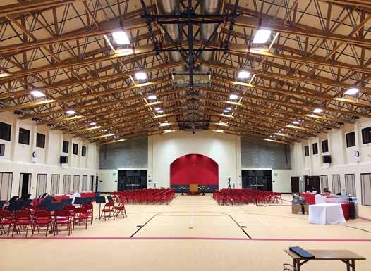
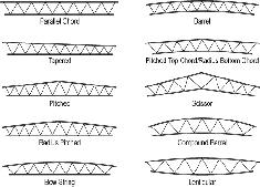
Figure 2. Open-web truss profles.
Scissor: Ideal for shallow depth trusses with vaulted interiors. Lenticular: A lens-shaped truss (curved top and bottom).
Design and Engineering Considerations
IBC 2015 Section 2303.4.1.3, “Trusses spanning 60 feet or greater,” requires that a registered professional be responsible for the design of both temporary and permanent bracing. Temporary bracing is any non-permanent element used to stabilize the trusses during the construction process. Te primary component of permanent bracing is typically the plywood or oriented strand board (OSB) roof diaphragm that laterally braces the top chords of the trusses. Other permanent bracing elements are used for conditions in which the bottom chord is in compression, such as wind uplift or cantilever conditions. Even without compressive forces, the bottom chord should be braced to hold the truss in proper alignment, which is usually perpendicular to the roof deck. Providing adequate temporary bracing enhances safety and prevents truss damage during installation. Permanent bracing helps ensure the truss will support the intended design loads. Structural Roof Panels Top chords in compression can buckle laterally if not properly braced. It is recommended that plywood or OSB-rated panels that form the roof diaphragm be fastened directly to the tops of the trusses to provide permanent lateral stability. If the truss top chord is a double-chord member, both top chord members should be independently fastened to the roof diaphragm to prevent lateral buckling. Alternate decking materials may lack adequate top chord buckling restraint. For example, structural insulated panels have large, single fasteners that may fall between truss chords or split the truss chords. Cementitious fber panels not only use large fasteners but may require structural adhesive to create a bond to brace the truss top chord adequately. Wood tongue-and-groove decking may not provide a diaphragm to brace the trusses unless the boards are fastened together or have structural panels installed over them to create the diaphragm. Metal decking may also lack diaphragm action if not properly designed. A wood cap attached directly to the top chords of the trusses may help address issues of oversized or closely spaced fasteners. Diaphragm Design with Modular Erection Modular erection involves a group of trusses that are assembled on the ground with most of the permanent plywood or OSB panels fastened in place to the truss top chords. Also, 2x4 top and bottom chord bridging with cross bracing is installed – typically ten foot on center – to brace the bottom chords. Tis entire assembled unit, which is very stable relative to a single truss, is referred to as a “truss module”. When trusses are erected in modules, the permanent roof diaphragm will have a continuous edge at eight-foot-on-center (based on standard panel dimensions). Te engineer must take this panel layup into account when designing the diaphragm. Most long-span open-web trusses have double chords, meaning the top chord consists of two separate members (usually 2x6 members), connected with pins and lock washers at truss panel points. It is common for the manufacturer to factory install a plywood cap on the trusses to transfer shear across the joint. Diaphragm nails should be long enough to penetrate through the plywood cap and into the truss chord. IBC 2015 section 2306.2 on woodframe diaphragms references the American Wood Council’s Special Design Provisions for Wind and Seismic (AWC SDPWS). Te AWC SDPWS provides diaphragm assembly Tables 4.2A, 4.2B, and 4.2C, in which nailed diaphragms can be used to determine allowable diaphragm shear. When using these tables and designing with double-chord open-web trusses, a nominal framing width of three inches should be employed when determining allowable shear. Te engineer should review the truss manufacturer’s allowable nail spacing into the truss chord to verify the closest allowable on-center spacing is not exceeded. Loading Te structural engineer’s drawings should provide all design loads, along with load duration factors and/or required load combinations. Following are some examples: • Snow loads, including any snow drifting or non-snow live loads
• Uniform design dead loads for top and bottom chords • Any wind or seismic lateral loads • Wind uplift loads • Other loads, including those for mechanical units or loads suspended from the trusses Engineers must also address other loads, such as sprinkler mains, which often are not known until after contract drawings are completed. Connections Open-web trusses typically include factoryinstalled bearing hardware. Te engineer should work with the manufacturer to verify gravity, uplift and lateral capacities during the design process and confrm if the engineer or the manufacturer is responsible for the design of any given connection. Usually, if the hardware is factory-installed on the truss, the truss manufacturer assumes design responsibility for the connection, but only if the engineer specifes the design loads. Be aware some truss hardware may only be designed for gravity or uplift load conditions. Additional hardware from another manufacturer may be required to resist lateral loads. Wall anchors and straps specifcally designed for use with open-web trusses are available. It is important to choose an anchor or strap that has fasteners compatible with the truss chords and bearing hardware. It is up to the engineer to specify the correct model. Bearings Specifcations for truss bearing hardware required bearing lengths, allowable feld tolerance, slope bearing requirements, and minimum chord cut-of lengths all vary based on the truss series and the specifc design application. Te engineer should address all of these requirements during the design process to ensure that there are no installation issues related to the bearing details. Defection Long-span trusses can experience signifcant vertical defection when loaded. It is advisable for the engineer of record to review the design defections and specify the truss camber for long spans. Te following situations are examples of when camber and defection should be evaluated: • Trusses located next to fxed elements such as walls • Defection limits related to suspended/ movable partition walls • Gap requirements over non-bearing partition walls • Top-of-wall bracing details continued on next page
• Long-term creep and short-term creep that can vary depending on truss chord moisture content and construction loads • Roof designs with potential for ponding With scissor profle trusses, limiting horizontal defection should also be considered. Truss Length Truss design length may exceed what the manufacturer can build or ship to a given area. Trusses can sometimes be manufactured in two sections and assembled in the feld using special connections where the sections meet. Although they are designed much the same way as any standard length open-web truss, long-span trusses present some additional considerations. It is recommended that the engineer works in close collaboration with the manufacturer during the design process, thus avoiding potential design and installation issues.
Open-Web Truss Installation Methods
Due to their long length and narrow chords, steps must be taken during installation to prevent buckling or rolling of the trusses. Open-web trusses less than 70 feet in length are usually installed one truss at a time with the use of strut bracing. Strut bracing is manufactured using light gage steel tubing with fattened ends that include punched nail holes positioned over the truss chords. Tey are designed to ft common truss spacing such as 16 inches, 24 inches, 32 inches, or 48 inches on-center. Te bracing is temporary in that the struts can be removed once the trusses are permanently braced with the diaphragm. Instability of the truss chords due to the truss self-weight, as well as temporary construction loads, is amplifed as the span increases. For
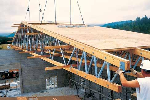
Figure 3. Workers are guiding a module of pitched trusses into place.
Figure 5. Spreader bar with proper pick locations lifted by a crane. Notice the second module in assembly jig on the ground.
spans over 70 feet, modular erection is recommended to avoid material damage, or worse yet, a work-site injury. Some manufacturers contractually require modular erection when spans exceed 70 feet. In addition to improving safety, modular erection can speed up the installation process (Figure 3). When using the modular erection method of stabilizing long-span trusses during installation, the structural engineer should include appropriate information in the contract drawings to let the contractor know modular erection is required. Following is an example of appropriate verbiage: “Te trusses shall be installed in rigid modules at least 8 feet in width, accurately assembled in a jig with fnal sheathing permanently attached while on the ground. Specifed bridging and bracing shall be installed in each module as detailed in the manufacturer’s drawings.” Trusses typically arrive at the job site on a fatbed trailer in banded bundles. When banded, the bundles are relatively stable, but it is still important to have the pick points spaced far enough apart to provide stability (Figure 4). Using a single forklift to move long span trusses should be avoided. Te truss bundle should be placed on dunnage and all trusses braced in preparation for removing the banding. Once the bands are removed, the trusses can be moved one truss at a time into a prebuilt jig to assemble the truss modules. A crane with nylon rigging straps long enough to widely space the pick points is typically sufcient to move the single trusses into the jig. Jigs should be located on level ground, be designed to support the trusses in multiple locations, and take the truss camber into consideration. Te purpose of the jig is to provide a safe way to space and align
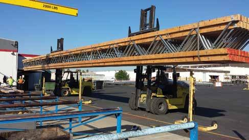
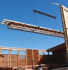
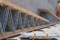
Figure 6. Delivered segments before assembly. Once assembled, they will form a 75-foot-long scissor pitched truss. Note the required steel-tube crossbracing in the foreground.
trusses squarely for attachment of bracing and sheathing while still on the ground. Once the modules are constructed, they will be ready to lift into place in a safe and efcient manner (Figure 5). As with truss design, the design professional can receive assistance from the manufacturer regarding bracing methods.
Examples and Applications
Some common applications for long-span open-web roof trusses are school gymnasiums, church gathering rooms, and light commercial construction – anywhere a big, open room is desired. Trusses can be installed in buildings with wood, concrete or masonry walls, including those located in high seismic zones. While spans can extend over 100 feet, the most common long-span applications range between 60 and 100 feet. Taylor Middle School Located in Millbrae, California, the 15,694 square-foot cafeteria of Taylor Middle School not only serves school lunches but is also a venue for graduations, board meetings, community meetings and even basketball and volleyball games. Te design team selected a scissor truss system that spans the width of the cafeteria and then left it exposed to create an open feel. Te 75-foot-long double-scissor trusses are eight-foot-on-center and meet seismic and other loading requirements (Figure 6). Lighthouse Baptist Church MultiPurpose Building While it is typical for a gymnasium to be located on the ground-foor level, not so for Lighthouse Baptist Church, where their only option was to go up. Te design and construction team created a frst-foor with ofces, classrooms, and a sanctuary, and a second-foor that hosts a basketball gymnasium with roll-out bleachers (Figure 7), to develop this unique multi-purpose building.
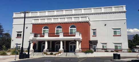
Figure 7. Te multi-purpose building for Lighthouse Baptist Church includes a second story basketball gymnasium.
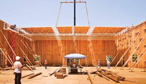
Figure 8. Modules of 89-foot-long pitched profle trusses for multi-purpose building hoisted into place by crane.
Te two-story, wood-framed building is 45 feet high and 22,464 square feet in size. Its 89-foot-long, pin-connected open-web trusses are spaced at 48 inches on-center and span the entire gymnasium. Left exposed, they create an attractive, clean-looking roof structure. Te team built the entire roof in modules on the ground and then lifted them into place by crane to keep construction simple (Figure 8). Morrell’s Electro Plating Located in Compton, California, Morrell’s is a metal fnishing provider for the aerospace and military defense industries. Teir 80,000-square-foot structure features 62 trusses, each 73 feet long. Te clear span of the trusses allows an obstruction-free interior to the warehouse. Te truss depths of just 36 inches were required to accommodate building height restrictions of the city. Te building includes concrete block walls with wood ledgers that support the trusses. Two hold-downs per truss end were used to anchor the walls laterally to the trusses (Figure 9).
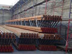
Figure 9. Tese single-piece 73-foot-long, top-chord- bearing parallel profle trusses will be installed onto wood-ledgers-connected concrete block walls.
Long-span, open-web trusses provide architects with design freedom and engineers with a choice in material selection. Te trusses are custom designed, detailed, and manufactured to meet the structural needs and design intent for the specifc application. Tey are economical and provide the added beneft of building with wood, which is considered a green alternative to steel or concrete.▪


