46 minute read
STRUCTURAL DESIGN
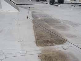
design issues for structural engineers Construction Science and Engineering, Inc., an architectural and engineering firm, has investigated several low slope roof applications with water stains, ponding, framing damage on the lower side of the roof span, and structural collapse. Further examination typically reveals a relatively level surface when compared to other roof locations (Figure 1). A similar occurrence is often found in exterior deck applications. (Figure 2). In studying this potentially problematic issue, two building code parameters were identified that contribute to low slope roof and deck serviceability issues. This article examines susceptible bays with respect to the ¼ in 12 design slope and code permitted deflection ratios. Part 2 will identify design and construction practices that contribute to serviceability issues.
Background
The 2015 International Building Code (IBC) identifies ponding instability as a design consideration for snow and rain loads. The 2010 edition of the Minimum Design Loads for Buildings and Other Structures (ASCE 7-10),
Building designers routinely stipulate within construction documents the well-known code minimum ¼ in 12 design slope for low slope roofs and exterior deck applications. This practice, on the surface, appears to eliminate the code requirement to investigate a susceptible bay. Additionally, common practice is to specify or accept minimum building code deflection ratios for low slope applications. However, many building designers apparently fail to give due consideration to footnote “e” in IBC Table 1604.3 which states in part; “The above deflections do not ensure against ponding…” A code defined deflection ratio is a function of the span and is therefore not influenced by material characteristics and design load variables. Each deflection ratio defines the deflection limits that are commonly approached as structural members are optimized for cost. Bender and Woeste recognized this relationship and showed a beam member installed to a ¼ in 12 slope that deflects to a code permitted deflection ratio results in an average slope less than ¼ in 12. They also noted the average slope is further reduced when a long-term creep deflection component is introduced. The Bender and Woeste (2011) study ¼ in 12 Design Slope and Water Drainage validates the author’s field observations for serviceability complaints and water retention associated with low slope roof Part 1 referenced by the IBC, defines “ponding” as the “retention of water due solely to the deflection and deck applications. The deflection curve was approximated using the properties of a circle to By Scott D. Coffman, P.E., SECB of relative flat roofs.” The standard requires “susceptible bays” be investigated to ensure verify the average slope was independent of the span and remained unchanged for a specified adequate member stiffness is present to pre- deflection ratio. Additionally, the lower end of vent progressive deflection. Specifically, “Bays the deflection curve was noted to be relatively with a roof slope less than ¼ in./ft. …shall be flat, which explained potential causes of observed designated as susceptible bays. Roof surfaces ponding. In the author’s company’s study, surwith a slope of at least ¼ inch per foot (1.19°) faces with a design slope of ¼ inch per foot or Scott Coffman is a Forensic toward points of free drainage need not be con- less should be considered as a susceptible bay. Engineer with Construction sidered a susceptible bay.” The phrase “toward Specifically: Science and Engineering, Inc. points of free drainage” is critical because it 1) The average slope of the deflected member in Westminster, SC. He can gives meaning to what is meant by a slope of is less than ¼ inch per foot; and, be reached at scottcoffman@ ¼ inch per foot. The same principle may be 2) At and near the lower reaction, constructionscience.org. applied to exterior decks, although decks are the deflected member is relatively not specifically identified within ASCE 7-10. horizontal or flat.

Y1 Average Slope Y3
Y4
L/2 L/2
SPAN (L)
SPAN (L)
Figure 3. Deflected shape of beam with uniform load. Figure 4. Average slope of deflected member
Figure 3 visually depicts the downward movement of a beam member subject to load and vulnerability to ponding at the low end.
Average Slope Example
The average slope for the performance of a member installed to a ¼ in 12 design slope and permitted to deflect to a code permitted L/180 ratio is illustrated by the following example: • Member Span: 25 feet • Roof Total Load Deflection Limit:
L/180 • Right Support Datum Elevation: 0.00 inches • Left Support Elevation:6.25 inches (Y1) • Midpoint Elevation: 3.13 inches (Y2) • Member Total Load Deflection (L/180): 1.67 inches (Y3) • Distance from datum to deflected member: 1.43 inches (Y4) The “average slope” is the slope of a line from the low-end support to the point of maximum deflection for a member. For a simply supported beam member subjected to a uniform load, the average slope is from the center of the span to the low-end support. In this example, the right support is the low end and point of free drainage. Figure 4 shows the original member slope and deflected shape. The distance from a level datum to the deflected member is 17⁄16 inches (Y4); the difference between the member’s original position and code permitted deflection ratio at the mid-span. The average slope from the center of the member’s deflected shape to the low-end support is 0.117 inches per foot, a slope less than 1⁄8 in 12 or nearly flat. When a member initially installed to a ¼ in 12 design slope deflects and approaches the total load L/180 code permitted deflection ratio, the average slope becomes less than 1⁄8 in 12. The calculated 0.117 in 12 average slope is constant for any span designed to the L/180 deflection ratio. ASCE 7-10 explicitly identifies member stiffness as a means to control progressive deflection of a susceptible bay. Design professionals typically specify a more limiting deflection ratio than required by the building code for the application to achieve a stiffer member. As expected, the average slope approaches the ¼ in 12 design slope for a stiffer member or a higher deflection design ratio. However, a beam element subject to gravity load deflects, and the average slope remains less than the designed ¼ in 12 design slope. Therefore, a beam element installed with ¼ in 12 slope requires a “susceptible bay” analysis based on ASCE 7-10, since all members deflect under load.
Deflection Curve at the Lower End
The lower end of the deflection curve is also a typical location for ponding, water stains, and damaged framing members (Figure 5). This opinion is based on observations made during forensic investigations. The vertical difference between a ¼ in 12 plane and the L/180 deflection curve was calculated for spans of ten feet to forty feet in 2-foot increments. The deflected shape crosses the horizontal datum in the region of L/16, creating negative slope and a “bowl” at the low end. A “bowl” naturally retains water and restricts free drainage or water discharge. Ponding or water retention should be expected toward the low end of a plane designed to a ¼ in 12 slope.
Long-Term Creep Effects and Example
Structural materials susceptible to longterm creep intensify the deflection curve. The IBC estimates the creep component of long-term deflection to be half the immediate dead load deflection or a 1.5 factor. The creep deflection component may approach the initial dead load deflection, a 2.0 factor for wood products. The 2014 Truss Plate Institute Standard (TPI) recommends the 2.0 factor where the building designer does not specify adjustment factors for serviceability. The 1.5 building code factor was applied by the author for a “best case” scenario to study the effects of creep deflection. Continuing the previous example, the initial dead load deflection is taken as the difference between the roof’s total load (L/180) and roof’s live load (L/240) deflection ratios. This calculates to 0.42 inches (1.67 – 1.25) for a 25-foot span. The long-term creep
Y1 Average Slope
12
1/4 DETAIL "A"
L/2 L/2
SPAN (L) L/16
DETAIL "A" Y1
12
Average Slope
1/4
L/2 L/2
SPAN (L) Y3'
Y4' Y2
12
Average Slope
L/2 1/4
DETAIL "B"
L/2
L/6
DETAIL "B"

L
Figure 7. Increased “bowl” is caused by member creep.
INTRODUCING DRIFT FASTCLIP™ SLIDE CLIP .
component is 0.21 inches (½ * 0.42). The center of the deflected member is 1.25 inches (Y4´) above the right end support (3.13 – 1.67 – 0.21). The average slope from the center of the member deflection curve to the support is 0.10 inches, or essentially no slope, and remains constant for any span (Figure 6, page 25). Although the average slope with a creep deflection component remains positive, albeit small, the low end of the member deflection curve remains of particular interest. The deflected shape crosses the horizontal datum in the region of L/6, creating a larger “bowl” area for ponding (Figure 7). As the dead load becomes a greater percentage of the total load, creep deflection increases and the “bowl” effect becomes more pronounced at the low end. It is imperative that deflection calculations include material long-term creep effects when compared to the ordinary live and total load code permitted deflection ratios.
Potential Design Solutions
Potential solutions to mitigate low slope serviceability issues are limited. ASCE 7-10 indirectly promotes a more stringent deflection ratio to prevent progressive deflection. The ASCE solution is imperfect because stiffer members increase the cost and the average slope remains less than ¼ in 12. A member or plane designed to an “average slope” of ¼ inch per foot is one method to mitigate ponding and resultant material damage. For a simply supported beam member subjected to a uniform load, the average slope line is from the point of maximum deflection at the center of the span to the low-end support. A more practical solution is a combination of increased slope and member stiffness. Design tools currently available afford a quick and efficient means for a designer to calculate the average slope of a member; the “average slope” being the slope of a line from the low-end support to the point of maximum member deflection. A combination of increased member stiffness and design slope that results in a surface with an average slope of at least ¼ inch per foot towards points of free drainage should eliminate susceptible bays.
Summary and Conclusions
The building code establishes the minimum parameters for building design. A member or system that satisfies each code parameter may create a less than ideal condition when multiple minimum code parameters are combined. The combination of the ¼ inch per foot design slope and a maximum permitted deflection ratio creates such a condition for free drainage. The code, however, does recognize this potential condition in IBC Table 1604.3 footnote “e” and instructs a building designer to investigate applications with insufficient slope or camber for ponding. Building designers, contractors, and perhaps code officials have come to believe a roof or exterior deck surface designed to the ¼ inch per foot slope is satisfactory because it meets building code intent. However, member deflection creates an average slope that limits free drainage and contributes to ponding toward the low end. Members optimized to a code permitted deflection ratio further reduce the average slope and may create a negative slope or a “bowl” at the low end that limits or prevents free drainage. The condition is exacerbated for materials susceptible to creep deflection. Beam elements designed or installed to the ¼ inch per foot slope should be considered a susceptible bay. In the absence of code performance limits for low slope roofs, a building designer should consider implementing a more stringent total load deflection ratio, increase the minimum slope for positive drainage, design to an “average slope” of ¼ in 12, or a combination of each. The practice should also be extended to decks.▪
Need a defl ection solution that also accommodates horizontal drift? Drift FastClip allows 2-inch vertical and lateral defl ection, and works with FastClip screws for friction-free sliding. Get more details and data at clarkdietrich.com.
2017 ClarkDietrich Building Systems ©


Software Continues to Evolve


NEW OFFERINGS, ADD-ONS, AND UPGRADES ASSIST ENGINEERS IN MEETING TODAY’S CHALLENGES
By Larry Kahaner
Companies that provide software for the engineering and construction industry are continually updating their off erings to keep pace with what structural engineers want and, most important, to keep up with code changes. At Dlubal Software, Inc. (www.dlubal.com/en-us), CEO Amy Heilig says that the latest addition to their 3D fi nite element analysis software, RFEM, is the RF-CUTTING-PATTERN add-on module. “We are beyond excited to off er this to engineers who specialize in the design of membrane and tensile structures, as the software market for this type of application is extremely slim. RF-CUTTING-PATTERN generates and organizes cutting patterns for membrane structures taking into account curved geometry, compensations, and overlaps with the minimum energy theory fl attening process.” She adds: “ is new module can be used in conjunction with RF-FORM-FINDING which determines the membrane’s pre-stressed shape used in the initial state for further static analysis. e supporting structure for the membrane can then undergo a full analysis design per AISC, ACI, NDS, and ADM. A complete structural solution for fabric, cable, and tensile membrane structures can now be achieved with the single design program, RFEM.” A recent company project is the Brock Commons, an 18-story mass timber, hybrid student residence currently under construction at the University of British Columbia in Vancouver, Canada, and designed by Dlubal Customer, Fast + Epp. “When completed in the summer of 2017, it will be the tallest mass timber hybrid building in the world at 174 feet high”, Heilig says. “ e structure is comprised of 16 fl oors of fi ve-ply cross-laminated timber (CLT) fl oor panels, a concrete transfer slab at level 2, and a steel-framed roof. e structural analysis for the CLT components was completed using Dlubal’s RFEM in conjunction with the RF-LAMINATE add-on module.” As far as trends are concerned, Heilig says that design engineers remain steadily busy which in turn correlates to an increased demand for a high performing structural analysis and design software. “We have seen a surge in cross-laminated timber (CLT) interest, as massive timber continues to be heavily marketed throughout the U.S. and Canada. RFEM remains the top choice for timber engineers for comprehensive CLT analysis and design per the 2015 NDS, in addition to member design per the NDS and CSA. We continue to see steel and concrete design dominate the structural engineering market, and this probably won’t change anytime soon. However, we are now seeing an increased demand for unique material and geometric designs as architects and owners are seizing opportunities to stand out with their structures. Dlubal caters to this exact scenario. We provide solutions for the structural engineer who is faced with complex structural geometry or in need of structural design of not only steel and concrete, but also glass, CLT, aluminum, timber, fabrics, and cables.” (See ad on page 30.) Benjamin Follett, U.S. Product & Marketing Manager, for SCIA Inc. (www.scia.net/en), would like SEs to know about SCIA Engineer 17. “For the U.S. market specifi cally, we updated all the steel codes to the newest versions; that is the 2016 AISC code and 2016 AISI code for cold form steel. e updates include new formulas, new references notations, and terminology.” He adds: “ ere also are improvements to the design and workfl ow of composite slabs, such as creating automatic load combinations. We have also added diaphragms. Simplifi ed diaphragms, rigid diaphragms, fl exible diaphragms, and semi-rigid diaphragms all have been requested by our users. ese users want to simplify a building or perhaps don’t want to go through the full slab design when they are not doing a concrete slab.” Says Follett: “As far as BIM is concerned, we have a new link directly with Revit, so it is support for the newest version SCIA 17 and the newest version of Revit 2018. It was more of a maintenance release for us, a bug-fi xing release. “We also improved our interoperability with a cloud BIM tool that we call BIM+. BIM+ is a free online BIM server. e goal of BIM+ for us at the Nemetschek Group is to have all our software utilize this online, cloud-based server to exchange models with other Nemetschek software,” he concludes. “Cold-formed steel design, and especially the AISI North American Specifi cation, can be a little foreign to most engineers,” says Clif Melcher, CFS Product Manager at Simpson Strong-Tie (www.simpson.com). “CFS Designer software by Simpson StrongTie can simplify and automate the design and engineering of CFS structures, and provide great time-saving solutions,” he says. “Many CFS engineers may know CFS Designer by its original name, LGBEAMER. Simpson Strong-Tie has upgraded the software and taken it to the next level. Similar to LGBEAMER, CFS Designer can automate common design components, including wall studs, beams, columns, wall openings, x-braced and sheathed shear walls,

floor joists, and rafters. In addition, it includes the latest codes and features a Stacked Wall Design tool that automates the design of up to eight stories of load-bearing CFS stud framing. A new, user-friendly interface as well as organizational and file management tools have been added. The software also has automated the selection of bridging and curtain-wall rigid and slip connectors,” Melcher notes. StructurePoint’s software (www.structurepoint.org) suite includes features which emphasize the solution of intricate scenarios or niche cases in reinforced concrete design, says the company’s Resource Manager, Dana Lee. “Our team routinely posts technical notes on our website to aid users in accessing the full range of capabilities built into the software for specific, frequently-encountered cases. Most recently, we have addressed the effective flexural stiffness for calculation of the critical buckling load of individual columns, as well as concrete type classification based on unit density. These technical notes, among many others, use the latest American (ACI 318-14) concrete codes and provide multiple options for solutions to fit a range of projects. These can be found on the Resources page of our website, along with various technically-focused tools to aid engineers in completing their most demanding projects.” Lee would also like SEs to know that their software manuals for each of the programs within the suite are now easily accessible on their website in multiple formats. “The online versions feature simple headings and easy navigation, including search and filters to efficiently access resources such as methods for a solution and dynamic design examples. The manuals are also available as PDF files.” StructurePoint is formerly the Engineering Software Group of the Portland Cement Association (PCA), and it continues to develop and enhance the full range of advanced software and engineering services to model, analyze, and design reinforced concrete structures, notes Lee. “Recent focus in the Middle and the Far East, where concrete design software is in high demand, has kept our team busy as we adapt to various business paradigms. StructurePoint has been supporting and growing alongside the global market by meeting the needs of engineers in six continents and over 50 countries. While we provide our products and services as an essential tool to academic institutions and engineering firms internationally, we continue to ensure the stability and growth of our local and national user-base.” Lee concludes: “With the experience and legacy gained over 60 years as PCA’s engineering software group, structural engineers continue to trust StructurePoint to extend knowledgeable support via consulting engineering services. Engineers everywhere value StructurePoint as a gateway to the vast resources and knowledge base of the cement and concrete industry. The promise of rising infrastructure spending in the U.S. economy is creating energy, excitement, and new opportunities for engineering firms to create proposals and feasibility studies. Clients experiencing this trend are tapping into StructurePoint’s concrete industry experience to relieve heavy workloads, augment their staff, and advise on all of their concrete project estimates, preliminary designs, and comparative studies.” (See ad on page 32.)
continued on page 33
ADVERTISEMENT–For Advertiser Information, visit www.STRUCTUREmag.org
RFEM 5
Structural Analysis & Design Software & Design Software
Kauffman Center for the Performing Arts Kansas City, MI, USA © www.novumstructures.com
DOWNLOAD FREE TRIAL
www.dlubal.com
Powerful, Intuitive & Easy
Steel Aluminum Glass Concrete Tanks Piping
JOIN US
September 21-23, 2017
IABSE 2017 Vancouver, BC Canada
October 12-13, 2017
2017 NCSEA Summit Washington D.C. Dlubal Software, Inc.
Philadelphia, PA (267) 702-2815 info-us@dlubal.com www.dlubal.com
Timber CLT Cables
LACKNER + RAML Ziviltechniker – GmbH © www.lackner-raml.at

VCmaster (www.vcmaster.com/en) has been developed with the needs of engineers in mind, according to company offi cials. ey note that the program intelligently combines technical calculations and word processing in one single user interface. Everyday tasks such as calculation, documentation, compilation, as well as the reuse of technical data and calculations, are tackled with their integral concept. Highlights of VCmaster include: • Uniform Documents: VCmaster off ers engineers a unique and comprehensive concept. Outputs of all structural analysis or CAD programs can be incorporated into VCmaster, guaranteeing a uniform and consistent layout. • Convenient Revisions: Positions and details are exchanged automatically, and reports are amended and checked by a click of the mouse. All revised pages are then subjectspecifi cally indexed. • Sustainable Benefi t: All digitally compiled VCmaster documents can be easily adjusted, combined, or reused at will. • Interactive Design of Structural Elements: VCmaster automates the design of structural elements. Formulas are presented in standard mathematical notation and calculated automatically. Material or section values are determined from stored databases. • Interactive Design Aids: VCmaster includes numerous predefi ned design aids for structural analysis. Engineers can create their own design calculations and combine them with existing templates to create design briefs. is year’s development focus for VCmaster has been on improving the handling of the software and simplifying data entry. VCmaster has been revised in many aspects to achieve this goal. Major improvements include: • Extended options for design and formatting. • Faster data entry due to the new favorites folder, pre-defi ned input lines, and automated completion of variables. • Easier checking of indices for page numbering and database queries. • VCcopy-technology, an intelligent alternative to the Windows clipboard.▪
ADVERTISING OPPORTUNITIES
Be a part of upcoming special advertorials in future issues.
To discuss advertising opportunities, please contact our ad sales representatives:
JOE MURPHY DENIS O’MALLEY
203-254-9595 203-356-9694, ext. 13
sales@STRUCTUREmag.org
ADVERTISEMENT–For Advertiser Information, visit www.STRUCTUREmag.org
National Council of Structural Engineers Associations OCTOBER 1114, 2017 · WASHINGTON HILTON · WASHINGTON, D.C.
NCSEA invites the best of the structural engineering fi eld to join us in Washington D.C. as we celebrate 25 years of bringing together structural engineers. e 2017 Structural Engineering Summit features education sessions specifi c to structural engineering, including 3 specialized panels and an entire track dedicated to young engineers. Flip to NCSEA News, pages 62-63, for more information on this year’s Summit!
WEDNESDAY, OCTOBER 11 8:00-5:00 NCSEA Committee Meetings All Attendees Welcome (See the schedule on www.ncsea.com) 4:30-5:30 Young Member Reception Young Members & NCSEA Board of Directors Only 4:30-5:30 Delegate Reception Delegates & NCSEA Board of Directors Only
5:30-7:00 Welcome Reception All Attendees Welcome
THURSDAY, OCTOBER 12 7:00-9:00 Delegate Interaction Breakfast Delegates, SEA Leadership & NCSEA Board of Directors Only
8:00-9:00 All Attendee Breakfast 9:00-10:00 Keynote: Shaking Up DC - e Insiders’ Story
Martina Driscoll, P.E., Principal & Unit Manager, Wiss, Janney, Elstner Associates and Terrence Paret, Senior Principal, Wiss, Janney, Elstner Associates
10:00-10:30 Break on the Trade Show Floor 10:30-12:30 ASCE Panel on How to Improve ASCE 7
Ron Hamburger, P.E., S.E., SECB; John Hooper, P.E., S.E. and Don Scott, S.E.; ASCE/SEI 7 Committee Leadership
12:30-1:30 Lunch on the Trade Show Floor
1:30–2:30 Concurrent Sessions
Track A Seismic Design of Diaphragms by the Provisions of ASCE 7-16
S. K. Ghosh, Ph.D., S.K. Ghosh Associates, Inc.
Track B NEHRP Recommended Seismic Provisions
Kevin Moore, C.E., P.E., S.E., Senior Principal, Simpson Gumpertz & Heger Inc. and Charles A. Kircher, Ph.D., P.E., Kircher & Associates
Young Engineer Track Young Member Mentor Roundtable
Seth Th omas, P.E., S.E., Chair of the NCSEA Young Member Group Support Committee 2:00-5:00 SEA Executive Director Roundtable SEA Executive Directors & SEA Leadership Welcome 2:30–3:30 Concurrent Sessions
Track A SEAOC Wind Design Manual - An Overview
Emily Guglielmo, P.E., S.E., Martin/Martin, Inc and Steve Kerr, S.E., Josephson, Werdowatz & Associates
Track B Solar Photovoltaic Systems in ASCE 7-16
Joseph H. Cain, P.E., Director of Codes & Standards, Solar Energy Industries Association (SEIA)
Young Engineer Track Wind Design Considerations for Joist/Joist Girder Structures
Tim Holtermann, P.E., Canam-Buildings
3:30-4:00 Break
4:00–5:00 Concurrent Sessions
Track A Assessment of Performance-Based Seismic Design Methods in ASCE 41 for New Steel Buildings
John Harris, Ph.D., P.E., S.E., research structural engineer in the National Earthquake Hazards Reduction Program of the Engineering Laboratory (EL), National Institute of Standards and Technology (NIST)
Track B You Can’t Just Delegate Everything Away to Others with Deferred Submittals
Ben Nelson, P.E., Martin/Martin, Inc.
Register now on www.ncsea.com to save $100!
Young Engineer Track YMGSC-Basics of Shear Wall Design
Moderated by Seth omas, P.E., S.E., Chair of the NCSEA Young Member Group Support Committee
5:00 - 6:30 Trade Show Reception
Network with the companies providing structural engineering products and software! 7:00 A Celebration of Structural Engineering at the National Building Museum Join CSI for a unique celebration of structural engineering, including dinner, champagne, cocktails, & live music.
FRIDAY, OCTOBER 13 7:00-9:00 Breakfast on Trade Show Floor All Attendees Welcome 8:00-9:50 Delegate Collaboration Session Delegates, SEA Leadership & NCSEA Board of Directors Only 8:00-9:50 Product Presentations All Attendees Welcome ese brief presentations will provide more information on products or software from our exhibitors. 10:00–11:00 Concurrent Sessions
Track A Cracking Within Existing Concrete Masonry Walls: When Are Calculations Required?
Jose Busquets, P.E., Bracken Engineering
Track B Structural Engineering Engagement and Equity (SE3)
Nick Sherrow-Groves, P.E., ARUP and Angie Sommer, S.E., ZFA Structural Engineers 11:00–12:00 Concurrent Sessions
Track A Tall Wood Buildings in the U.S. – A Codes and Standards Update
Lori Koch, P.E., American Wood Council
Track B Networking Strategies: Even Introverted Engineers Can Network Eff ectively!
Jennifer Anderson, Career Coach
12:00-1:00 Lunch on the Trade Show Floor
1:00–2:00 Concurrent Sessions
Track A State of the Practice: Blast Design of Building Facades and Structural Systems
Cliff Jones, P.E., S.E., Project Engineer, Protection Engineering Consultants
Track B Shhh...It’s No Secret! Ideas to Help Grow Your Firms Clientele and Advance Your Career
Jana Monforte, Associate and Director of Marketing/Business Development, Wallace Engineering, and Sarah Appleton, P.E., S.E., Principal, Wallace Engineering 2:00–3:00 Concurrent Sessions
Track A e Structural Innovations of the New Mercedes Benz Stadium
Erleen Hatfi eld, P.E., S.E., AIA, Buro Happold
Track B Contract Negotiation as a Tool for Managing Project Risk
Gail Kelley, P.E., Esq., LEED AP
3:00-3:30 Break
3:30–4:30 Concurrent Sessions
Track A Evaluation and Retrofi t of Existing Structures for Mitigation of Progressive Collapse
Aldo McKay, P.E., Protection Engineering Consultants
Track B Applied Business Mechanics Understanding Your Accounting & Financial Systems
John Tawresey, S.E., F.TMS, F.SEI, Chief Financial Offi cer, KPFF Consulting Engineers
6:00-7:00 Awards Banquet Reception 7:00-10:00 Awards Banquet
SATURDAY, OCTOBER 14 8:00-9:00 Breakfast All Attendees Welcome 9:00-12:00 Annual Business Meeting Open to All Attendees
HANCOCK’S TILT

REVITALIZATION OF THE HANCOCK OBSERVATORY
By John Peronto, S.E., P.E., SECB, LEED AP and Christian DeFazio, P.E., LEED AP
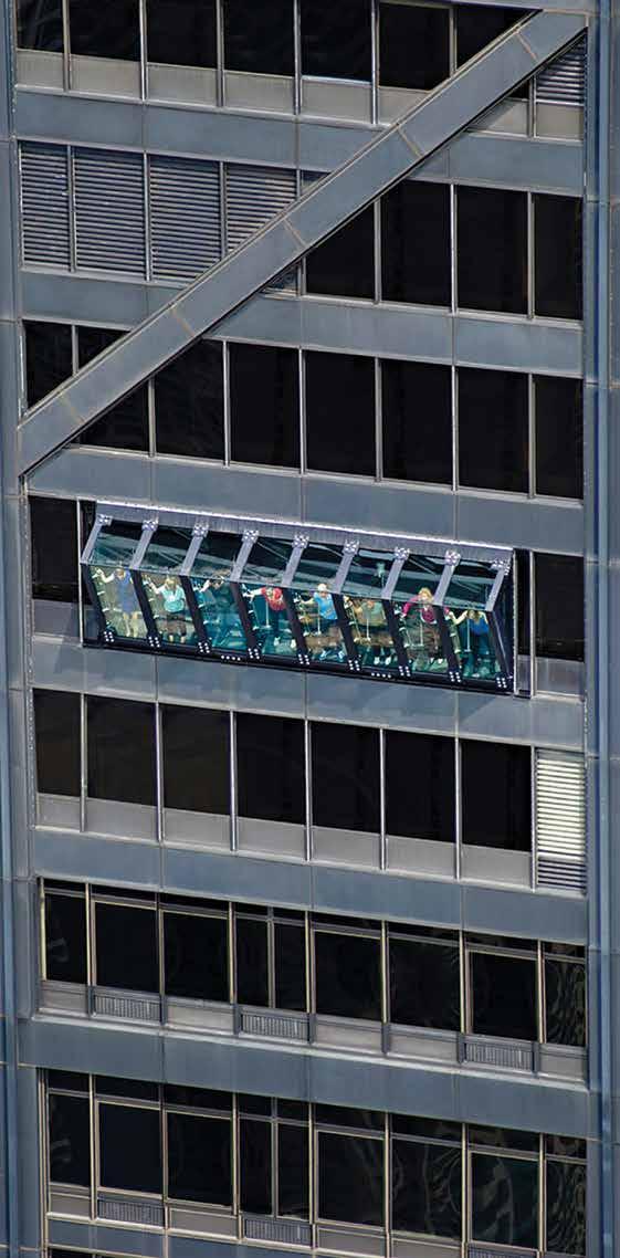
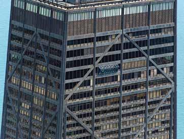
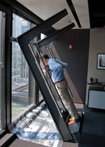
In early 2013, Thornton Tomasetti (TT) partnered with colleagues at Montparnasse 56 (M56), who had recently purchased the 94th-floor observatory in Chicago’s iconic John Hancock Tower, with a plan to modernize and revitalize the experience for its visitors. The M56 plan involved gutting and modernizing the interior space and installing a unique attraction that would add an adventure element experience for guests. The concept of “tilting” patrons outside the footprint of the tower was pitched by M56 as a way to provide a one-of-a-kind thrill, taking full advantage of the Hancock Tower’s height and spectacular views of Chicago.
Key Challenges
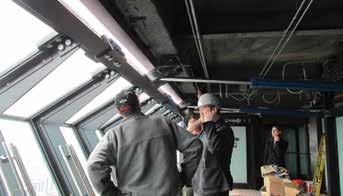
Designing and constructing a fi xed-tilted exterior curtain wall is no easy task, so taking that concept to the next level and developing an operable exterior wall with the ability to safely hold observatory patrons was a complex challenge. A steel-framed operable wall skeleton was developed to provide a robust and durable system that would be capable of operation 7 days a week. A steel frame provides excellent fatigue resistance and element ductility, as well as a clear load path. Integrated into the steel frame were structural glass components. e powered actuation system was also a direct part of the structure’s load path, so full-scale static load proof testing was done on the actuators to ensure their published load carrying capabilities. Ergonomics and patron experience required evaluation to test the concepts of thrill and comfort. For this challenge, TT fabricated a fullscale mockup of a single bay of the Tilt. is mockup was utilized by surveying the experiences of both a random sampling of TT and M56 staff to evaluate the comfort of the geometry, vertical hand railing, tilt angle, tilt speed, and tilt motion profi les.
Hancock’s tilt.
The final and very important challenge of maintaining the integrity of the world-famous architecture was also addressed by designing the Tilt structure’s geometry to mimic the existing exterior wall expression.
Mechanism and Components
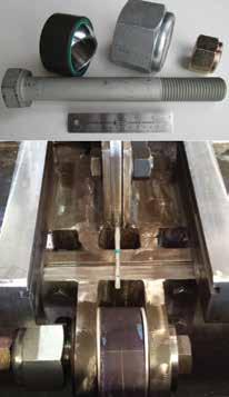
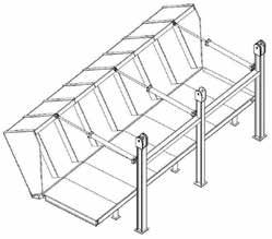
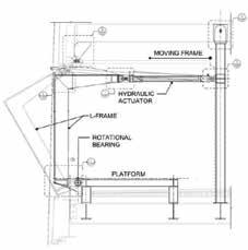
The Tilt system is a mechanized steel and glass structure that is comprised of three main components: • 3-Dimensional Steel L-Frame • Rigid Steel Platform at the Base • Overhead Actuation System The 3-D steel frame structure of the Tilt is 27 feet wide and 7 feet tall and can hold eight patrons at a time, one in each module. The geometry of this frame fits in one complete bay of the Hancock Tower and can rotate 30 degrees outward from the face of the tower’s exterior. A 30-degree angle was determined to be a point where the majority of patrons would have their center of gravity outside the exterior face of the tower while maintaining a reasonable clear height for patron modules, as this height is controlled by rotational clearance of the L-frame and the existing structure of the building. Rotational joints are located at three points along the base of the L-frame and are comprised of PTFE spherical bearings with custom machined AISI 4140 quenched and tempered hollow sleeve bolts, each containing an internal ASTM A320 L7 high-strength bolt for redundancy. These three locations serve as the rotational frame’s anchorage to the rigid steel platform at the base. W8 and W6 PTFE rotational joints and redundant pins. wide-flange beam members, which were posted down to the existing W18 floor beams, comprise this rigid base platform. Hydraulic actuators, with 4-inch diameter bores and 2.5-inch diameter rods, are located at three locations overhead and are aligned in plan with the three lower L-Frame points of rotation. These actuators are capable of resisting forces over 40,000 pounds and are digitally controlled with the ability to be programmed for different motion profiles and push-pull speeds. A hydraulic pumping system was installed in the mechanical space of the tower core area, which serves to power the Tilt actuation system. Overhead end-stops comprised of steel plates and rubber buffers were mounted to the underside of the existing spandrel beam to prevent over rotation of the L-frame. These stops are engaged by steel armatures, which are welded to the top of the L-frame, contacting them if the frame were to rotate beyond 30 degrees. With the cyclical nature of the Tilt mechanism, a detailed fatigue analysis was conducted utilizing both AISC design approaches and ASME fatigue design approaches like those developed by Shigley. Special detailing and testing requirements for welded connections and their base metals were also developed to be in accordance with AISC’s fracture critical detailing requirements and AWS D1.1 requirements for “cyclically loaded structures.”
Wind Tunnel Testing Program
At a height of 1030 feet above grade, actual wind loads for the design of Tilt would be much greater than those required by the Chicago
Tilt system. Tilt in use.

Building Code and are greatly influenced by the surrounding tall building topography. The Boundary Layer Wind Tunnel Laboratory at the University of Western Ontario was engaged to address this issue and conduct a High-Frequency Pressure Integration test (HFPI) at a scale of 1:200 of the top of the Hancock Tower, with the Tilt both open and closed. These loads were then utilized for the design of the Tilt structural steel frame, actuation system, and structural glass elements. Wind climate data was also utilized to better understand daily and weekly operational wind speeds, and corresponding wind pressures, that the Tilt would experience regularly.
Structural Glass
The glass elements of the Tilt are assemblies of 3⁄8-inch thick fullytempered glass panels with DuPont SentryGlas laminate inner layers. The front elements are comprised of three glass panels and two laminate inner layers, and the side and overhead elements are comprised of two glass panels and one laminate inner layer. The design of these assemblies was based on the results of the wind tunnel test wind pressures, and considering the glass panel assembly as a “Glass Walkway” in accordance with ASTM E2751-11. All panels are continuously supported along their edges and were analyzed in both SJ MEPLA and ABAQUS to evaluate their performance. The finite element analyses indicated that only two 3⁄8-inch thick glass panels with a single SentryGlas inner layer were required for the front main elements; however, the third layer was kept at these locations as a redundant layer for added safety. connections and implemented by M56. Each quarter, component and member connections are inspected and maintained, as required, to ensure that the Tilt’s condition is in general conformance with the original design intent. All inspections conducted by M56 are performed in conformance with AISC, AWS, and ASTM requirements for cyclically loaded structures.
The Tilt Experience
The Tilt system is an understandable, robust, and regularly maintained structural steel and glass mechanism that has been offering Chicagoans, and its visitors, a safe but unique and exhilarating experience in the much loved John Hancock Tower.▪
John Peronto, S.E., P.E., SECB, LEED AP, is an Associate Principal with Thornton Tomasetti. John designed the mechanized Tilt structure, for which he is a Patent Inventor. He can be reached at JPeronto@ThorntonTomasetti.com. Christian DeFazio, P.E., LEED AP, is a Senior Project Engineer with Thornton Tomasetti and served as the Project Manager of Tilt through construction. He can be reached at CDeFazio@ ThorntonTomasetti.com.
Project Team
Inspection and Maintenance Program
As the Tilt is a machine in addition to being a structure, a required regular Quarterly Inspection Program was developed for the steel Owner: Montparnasse 56 USA Structural Engineer: Thornton Tomasetti Contractor: Cupples
“ Get used to being ahead – with JORDAHL® anchor channels.“
Elisabeth Smith, Development Engineer at JORDAHL
1913 – First anchor channel manufacturer.
2013 – First IAPMO uniform ES anchor channel product evaluation. – First anchor channel design software based on IBC and IRC building codes.
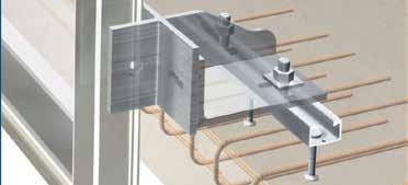
For more than 100 years JORDAHL® anchor channels and T-bolts have guaranteed the reliable anchoring of loads to concrete. Providing simple and fast installation, the JORDAHL system provides easy location adjustment for structural concrete connections without the time consuming hassle of welding or drilling. Hot rolled channel pro les provide high capacity and reduce in-built stresses allowing high dynamic load capability. This enables their ability to accommodate both high and rapidly uctuating loads over millions of cycles without metal fatigue. Just the sort of anchoring reliability needed for your project. With reliable performance veri ed by IAPMO Uniform ES Report #0293 and City of Los Angeles Research Report RR25797-T, JORDAHL® anchor channels are easy to design according to IBC, IRC, ACI 318 Appendix D, and ICC-ES AC 232, using our innovative JORDAHL® EXPERT software. The software can be downloaded for free from our website.
Our team off ers unequalled customer service and technical experience. We would be pleased to off er you additional assistance, and look forward to working with you.
DECON USA INC. 103 East Napa Street, Suite B Sonoma, CA 95476 Tel (866) 332-6687 www.deconusa.com

Use of Innovative Software Helps Reduce Costs and Project Delivery Time
By Katherine Flesh
Set to be the United Kingdom’s second tallest building next to the Shard skyscraper, 22 Bishopsgate is a 62-story, 912foot (278-meter) glass-clad tower that will sit at the center of a cluster of high rises in London’s Financial District. PLP Architecture conceptually designed the building, featuring 120,000 square meters (nearly 1.3 million square feet) of offi ce space, retail shops, fi tness centers, educational facilities, restaurants, and an open viewing terrace and observatory, in a bid to create the city’s fi rst vertical village. WSP Parsons Brinckerhoff (WSP) was retained to manage the structural modeling and design, as well as provide multi-discipline engineering services to ensure sustainability, achieve a BREEAM excellent rating, and be the fi rst in London to adopt the WELL Building Standard promoting the health and well-being of the building’s 12,000 occupants. e £1.5 Billion (approximately $1.9 Billion US) project required that 22 Bishopsgate be built on the site of a previously unfi nished building, the Pinnacle, where the foundation, basement, and partially constructed core (called the “stump”) of this structure remained. e new tower needed to incorporate the former Pinnacle’s foundation and three stories of basement structures. In addition to the site constraints amid several high-rise buildings, a tight timeline, and budget requirements, “ e challenge was to marry the superstructure, which did not correspond to where the foundations were,” explained WSP structural engineer Diego Padilla Philipps. e project team used Bentley Systems’ RAM Structural System and RAM Concept to provide WSP an integrated BIM solution to structurally design an effi cient building that would be larger than, and completely diff erent from, the Pinnacle design.
Recycling the Foundation
Working cooperatively with local structural specialists, WSP chose to demolish the seven-story Pinnacle stump and analyze the interaction between the new design and the existing basement and foundation structural elements to determine what could be salvaged. Said Philipps, “We used RAM Concept to analyze the complicated geometry and export the spring reactions for the piles from the geotechnical analysis, and tried to make them compatible and interpret how the foundation was going to work.” Since the core footprint of 22 Bishopsgate is larger than the Pinnacle, the team determined that if they added new raft and pile caps to adapt the existing supports to transfer the structure’s weight, they could establish the additional foundation capacity for the bigger building while still using 100 percent of the former Pinnacle’s foundation. Saving and reusing the existing foundation not only reduced costs but also minimized impact to the environment on this multi-use tower project.
Innovative Solutions
Because the footprints for the two buildings did not match, the team decided that the basement was the best place for the substructure load transfer structures. Using RAM Concept, WSP
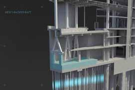
analyzed and modeled the three basement floors to determine how to build around and through them to optimize the transfers. On the north side of the structure, the project team designed three columns to support the 62 stories. WSP designed a raft to spread the loads for the three columns into the existing foundations. However, the raft could not support the loads, so the project team used A-frames to distribute the weight appropriately. Due to the waste management strategy implementation on the south side of the structure, the team could not use a vertical column going down to the foundation. WSP needed to incorporate an inclined column on this side of the structure, with high-strength cables to tie the column to the core. Similar to the basement transfers, the superstructure also required some elements to be transferred using inclined columns. However, while the basement’s inclined column was tied to the core, the superstructure did not lend itself to this type of support because the high-strength cables would interfere with the services running through the openings at these levels. To resist the lateral forces generated by an inclination spanning 50 stories high, WSP used RAM Structural System to analyze and design a horizontal transfer system where the floor plates behaved horizontally. Having columns at different positions throughout the superstructure, without corresponding foundations in the substructure, required WSP to design concrete walls all the way around to transfer the loads. The integrated software solution WSP used resulted in an innovative design solution that salvaged the existing basement structure.
BIM Advancements
To design the floors and determine the optimal shape of the overall structure, WSP linked RAM Structural System with Fabsec and Revit. Stated Philipps, “At some point in the design of the project, it was requested that we transfer all the elements to Fabsec... so we integrated RAM with Fabsec.” The team used RAM Structural System to analyze the steel frame for the floors and exported all the elements to Fabsec for design. Linking the two technologies allowed for the integrated design of the steel-plated floor
22 Bishopsgate Tower.
“The technology allowed for an efficient building design. We achieved 100 percent re-use of existing foundations, 50 percent re-use of the existing basement, and 30 percent more building space than the previous scheme.” — Andrew Woodward,
Director, WSP Parsons Brinckerhoff
“22 Bishopsgate is one of those rare projects that truly showcases the ingenuity of the engineers to deal with difficult site conditions and demanding program requirements to develop a truly innovative solution. Using innovative technology enabled WSP to consider over 50 alternate designs, and address complex 3D geometric irregularities and construction conditions to meet the demands of this amazing project.” — Raoul Karp, Vice President, Analytical Modeling Product Development, Bentley Systems beams, and facilitated seamless collaboration and information mobility with the client to meet the project’s changing demands. Furthermore, the team conducted up to 70 iterations to achieve the required design. With each iteration taking one or two engineers a week to model, WSP used Revit integrated with RAM, through Bentley’s Integrated Structural Modeler, to produce drawings and models simultaneously. This integrated approach accelerated the structural design process, reducing engineering and modeling time from 70 to 43 weeks, a reduction of nearly 40 percent.
Interoperable Technology Drives Design
Using Bentley’s interoperable applications for schematics through to construction design provided efficient and economical solutions within the tight time frame, as well as ensured strict compliance with European regulatory codes. The final design for 22 Bishopsgate was a structural steel frame that was 15 percent lighter than the Pinnacle design, with an efficient shape housing 30 percent more floor space and designed to achieve an excellent BREEAM rating and promote the health and wellbeing of its occupants.
Fast Facts
• 22 Bishopsgate is set to be London Financial
District’s tallest building and the city’s first vertical village designed to promote the health and well-being of its occupants. • WSP used RAM to design the structural system of the multi-use tower, incorporating existing structural elements from the previous
Pinnacle building. • The final design was 15 percent lighter and 30 percent larger than the original Pinnacle design.▪ Katherine Flesh is the Director of Analytical Modeling that leads the marketing strategy and positioning for Bentley’s Bridge, Offshore, Pipe Stress, Site Optimization and Structural products. She can be reached at katherine.flesh@bentley.com.
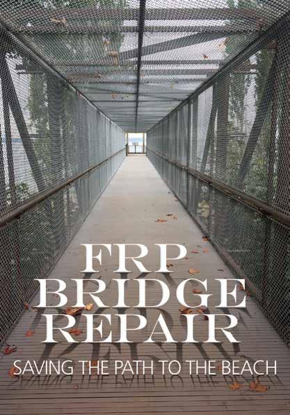
Perched on a bluff along the shore of Puget Sound, Howarth Park is a heavily wooded and frequently used public park in Everett, Washington. With its spectacular views of the Sound and small beach at the water’s edge, the park is very popular. However, like most of the eastern shore of Puget Sound north of Seattle, the actual beachfront is cut off from the uplands by the Burlington Northern Santa Fe (BNSF) railroad line. The public must cross a pedestrian bridge over the railroad tracks and descend down to the beach level on a wooden stair tower to access the beach.
The Existing Bridge
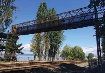
The existing pedestrian bridge is a nine-foot tall, eight-foot wide, two-span steel box truss structure that spans 49 feet from the hillside abutment to its center steel support tower, and then 80 feet across the BNSF tracks. This bridge, built in 1987 to replace an earlier timber bridge, was constructed entirely of weathering steel tubular sections. It was designed and built by a large national bridge design-build firm and was constructed economically, with small, thin-walled hollow structural sections (HSS). Many of the HSS truss members were 1⁄8- or 3⁄16-thick. It is likely that weathering steel was chosen for its natural weather protection and low maintenance attributes. About the time that this bridge was built, weathering steel was very popular for bridges and other structures throughout the country. However, some issues were starting to come to light and, in 1989, the Federal Highway Administration (FHWA) published a Technical Advisory, Uncoated Weathering Steel in Structures, which presented guidelines for the proper use of weathering steel. This document outlines several situations in which weathering steel is not recommended. Unfortunately, several of these situations could exactly describe the Howarth Park pedestrian bridge. FHWA guidelines include: 1) weathering steel should not be used where the atmosphere is wet for long periods of time; 2), weathering steel should not be used in a marine environment; and 3) weathering steel should not be used where site conditions don’t allow rapid drying, or where detailing may cause trapping of water on the steel surface. All of these conditions exist at the site of this structure, located on a bluff overlooking the Puget Sound.
The Existing Conditions
Weathering Steel
The owner was concerned about the condition of the bridge, as some excessive corrosion of the truss members had been observed near the hillside abutment. That end of the bridge is shielded from the drying action of the wind by surrounding trees and vegetation as well as the abutment itself. KPFF was requested to perform an assessment of the integrity of the existing bridge. It Weathering steel is often was decided that a survey referred to by the trade name of remaining steel thickof Cor-Ten, or Corten as ness should be conducted originally produced by the US Steel Corp. It is available By Greg Schindler, S.E. and Sara Roberts, S.E. on representative members throughout the structure. in various ASTM standards, Bridge walkway with new FRP decking. This was based on visual including A588 and A847 observation of the members (for pipe and tubes shapes), and has a special chemical makeup that and the knowledge that the original thickness of the steel members causes the surface to develop a protective oxide patina that can reduce was thin. Mayes Testing Engineers conducted ultrasonic testing of or eliminate the need for a protective coating. Initially, this patina the HSS section thicknesses of selected members of all parts of the develops similarly to corrosion of normal carbon steel. However, once bridge structure. the patina stabilizes, it forms a dense barrier between the base metal The primary members of the box truss – the chords, diagonals, and and the external elements. Some additional corrosion continues over cross beams – all were found to have minimal loss of section. The the life of the structure but at a very slow rate. Thus, the patina protects protective patina seemed to be performing as intended. The walkthe steel from the atmosphere. The successful use of weathering steel ing surface of the bridge consisted of 3x12 timbers laid across three depends on several factors, but key among them is one crucial design HSS 4x3x1⁄8-inch longitudinal stringers, which in turn rested on HSS concept – the steel must be allowed to dry fully between wettings. If 5x3x3⁄16 cross beams at the truss bottom chord panel points. When the steel is used in conditions that cause it to stay wet for long periods some of the timbers were removed to test the HSS stringer members, of time, the oxidation process continues beyond the protective patina it was discovered that many had corroded so badly that large holes stage, and detrimental corrosion will develop. were present on the top faces. This was the result of a design detail
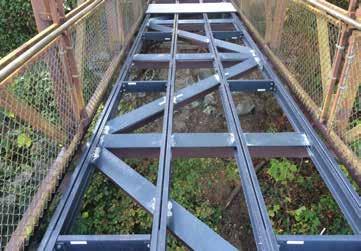
Bridge during repair. New FRP deck framing.
that allowed the wood members to prohibit drying of the steel surface. Also, the timbers were bolted to the stringers with bolts tapped into the steel tubes. This allowed water to make its way into the tubes, corroding them from the inside. In addition, there was a lot of sand trapped in the joints between the timber walking surface members. The foot traffic from the beach delivered a continuous supply of chloride-laden beach sand to the steel surface. As a result of this discovery, the bridge was immediately closed to the public and a design commenced to replace the degraded members.
Repair Design
Several types of decking were investigated as options to replace the timbers, and it was determined that Fiberglass Reinforced Plastic (FRP) T-bar pultruded grating would provide the best alternative as it is weather resistant, non-corroding, and lightweight. The open cross-section allows unrestricted air flow to the steel truss members. Initially, the repair design intended to replace the corroded stringers with new weathering steel HSS sections. During discussions with the FRP grating supplier, Fibergrate Composite Structures, it became apparent that a better long-term solution would be to use FRP structural members for the stringers. The three HSS 4x3 deck stringers were replaced with four stringers of 6-inch by 3⁄8-inch double FRP C-shapes, also provided by Fibergrate. New weathering steel tabs were welded to the tops of the existing cross beams and the FRP C’s were bolted to these. The only members of the existing primary steel box truss that were replaced with new weathering steel were a few lower chord diagonals and cross beams near the abutment end of the pedestrian bridge. These members, as well as strategic portions of the existing steel structure where there was a possibility of continuous wet conditions, were coated with a high-performance paint system. In keeping with current common practice, the overall approach was to paint weathering steel in portions of the bridge where excessive moisture or inadequate air flow was likely. The chosen FRP decking has a T section with small spaces at the walking surface. This shape is often used near pools and other places where people walk barefoot. It was chosen for the Howarth Park project to minimize the possibility of pedestrians dropping small items through the cracks onto the active railroad lines below. Also, to minimize the buildup of sand on the remaining steel cross beams and diagonals below the deck, flat sheets of ¼-inch FRP were installed above those members as sloped “sand shields” to shed the sand that falls through the grating. Another benefit of using FRP members to replace existing members is that FRP is lightweight, an important factor for an existing structure with little reserve capacity. The repair approach decreased the weight imposed on the structure, as well as the seismic mass. continued on page 47
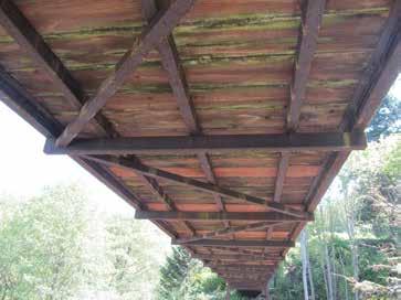
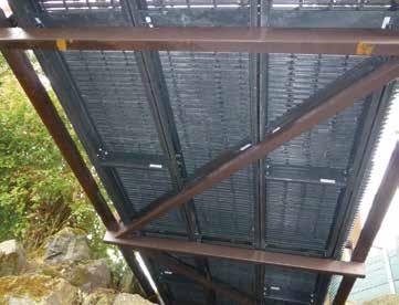
An additional consideration in choosing light weight FRP members to replace existing ones is that the Howarth Park pedestrian bridge is in a remote location, with limited access. e remote site meant that the contractor, Forma Construction, was required to hand-carry all construction materials and equipment to the site. Very little fi eld welding was required in the new design, and the FRP Typical corrosion in steel stringers. members were connected with stainless steel bolts or self-tapping screws. e sand shields were connected with stainless steel gauge metal clips normally used for wood construction. e entire project was accomplished with hand tools. e FRP supplier produced shop drawings for the members, similar to steel fabrication drawings. Once construction started, the process went smoothly. e biggest challenge on the project turned out to be the lengthy process of getting approvals from the railroad to work over a highly traffi cked, active railway.
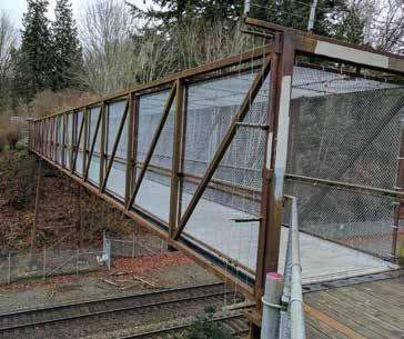
Completed project.
Project Team
Conclusion

Owner: City of Everett Parks and Recreation Structural Engineer: KPFF Consulting Engineers, Seattle, WA Testing Agency: Mayes Testing Engineers, Inc., a Terracon Over the course of its 30 years, a majority of the Howarth Park pedestrian bridge weathering steel members performed as intended with regard to corrosion, despite being located in a marine envi Company, Lynnwood, WA Contractor: Forma Construction, Olympia and Seattle, WA FRP Structural Sections: Fibergrate Composite Structures ronment. Only where detailing or natural shielding of the bridge prevented adequate drying of the steel did the steel corrosion continue to a dangerous state. With weathering steel, proper design and detailing to allow air circulation and thus drying DO YOU VALUE INTEGRITY? cycles is essential. e choice to replace some weathering steel members with At Fibergrate, we do. FRP members allowed for effi cient design and construction. Typically, FRP is used in caustic environments such as chemical plants or proximity to salt water, but the use of FRP structural members for this pedestrian bridge repair enabled the work to be KNOW FRP. KNOW EXPERIENCE. KNOW FIBERGRATE. completed effi ciently with corro- ∙ Fiberglass Reinforced Plastic ∙ 50+ years manufacturing ∙ Engineering services sion-resistant materials. e bridge is now re-opened to the public and will provide many years of additional ∙ Corrosion resistant ∙ Lightweight ∙ Low maintenance ∙ and supplying FRP solutions Engineered to withstand the harshest environments ∙ ∙ ∙ Local sales Fabrication facility Product warranty service.▪
Greg Schindler, S.E., is an Associate at KPFF, Seattle. He is also a Past President of NCSEA and is a member of the STRUCTURE magazine Editorial Board. Greg can be contacted at greg.schindler@kpff .com. Sara Roberts, S.E., is a Principal at KPFF, Seattle. Sara can be contacted at sara.roberts@kpff .com.
Don’t compromise your integrity. Specify Fibergrate FRP today.
To learn more, visit www.fibergrate.com 800.527.4043 | info@fibergrate.com
