
55 minute read
Structural Rehabilitation
renovation and restoration of existing structures
Performing renovation or restoration work on historic houses of worship presents a unique set of challenges for design professionals, and in particular structural engineers. These structures often feature large open-space areas, archaic structural systems and hard-to-define load paths, and varying degrees of deterioration or distress (often lack of maintenance and upkeep driven). All of these factors can make even the most simple-seeming renovation projects difficult, unique, and, in some cases, even stressful. Depending on the scope of planned renovations, structural upgrades aimed at preserving safety and mandated by building codes may also be triggered, which can be hard to implement or cost-prohibitive for structure types typical for historic houses of worship. However, renovating older, historic buildings to keep them functional and to equip them with modern amenities is a necessary undertaking. Understanding the inherent challenges at the outset of a project is key Divine Design: Renovating to making the renovations successful. Historic and Preserving Historic houses of worship are commonly part of the Houses of Worship social fabric of neighborhoods, and it is important to preserve them for the Part 1: Foundations benefit of the community, as well as for their architectural significance. By Nathaniel B. Smith, P.E. and Milan Vatovec, P.E., Ph.D. This article discusses commonly encountered structural issues on renovation projects of this type, and provides guidance on ways to address them. Part one of this series focuses on foundations. Parts two and three, to be published in upcoming issues of STRUCTURE magazine, will focus on wall and roof systems, respectively.
Nathaniel B. Smith, P.E., is a Senior Project Manager at Simpson Gumpertz & Heger’s office in New York City. He serves as Project Manager on numerous projects involving repair and rehabilitation of houses of worship. He can be reached at nbsmith@sgh.com. Dr. Milan Vatovec is a Senior Principal at Simpson Gumpertz & Heger Inc. He serves as the Principal-in-Charge of numerous repair and rehabilitation projects. He can be reached at mvatovec@sgh.com.
Foundations
Foundations are a critical component of any building structure; however, they also pose a significant maintenance and troubleshooting challenge as main foundation components are typically buried below grade and not readily accessible. Modern reinforced-concrete foundations typically require little if any maintenance over the life of a building. However, historic buildings commonly feature stone masonry and other archaic foundation systems that are more susceptible to damage due to movement or changed load paths, as well as deterioration due to exposure to moisture or other environmental factors. As a result, they require periodic evaluation, troubleshooting, and maintenance.
Stone Masonry Walls
Unreinforced stone masonry is a brittle building material, and is susceptible to damage from
Typical stone masonry foundation wall.
almost any type of movement. The actual construction details and quality of construction invariably affect the robustness and in-service performance of the walls. Stone masonry walls come in a variety of styles, and usually reflect the vintage of the building, the materials that were readily available at the time of construction, and the style of the local craftsman that built the wall. High quality walls are typically constructed from cut-stone fully laid in mortar. The mortar in these walls helps to hold all of the pieces together, and enables them to act as a single, homogeneous component. Sturdiness of such walls is always greater than that of dry-laid stone walls. However, while dry-laid walls do not contain any (or much) mortar, if they were carefully constructed they could be fairly robust. A dry-laid stone constructed with cut stone will typically be more robust than a wall constructed from irregularly shaped stones. In the worst case, one may encounter a rubble stone wall that was constructed by basically dumping stone in a trench with some mortar to “hold things together.” Poor quality of construction of such walls makes them very susceptible to damage and performance issues. Movement of foundation walls can occur for a number of reasons; the two most common are related to settlement of the soil below the foundation, and/or lateral soil pressures on the cellar portion of the foundation walls. Because of the brittleness of masonry walls, differential settlement will typically result in cracks developing at mortar joints and in shifting of the stones themselves. This distress will often translate up the height of the building, and can also result in rotation or other out-of-plane movement of the walls above. Lateral soil pressures, on the other hand, often cause bowing or leaning of the masonry walls. The walls typically span vertically between the cellar floor and the first floor, and are incapable of resisting the induced bending without distress. Wall cracking can be locally repaired through a number of conventional methods (e.g. repointing, brick stitching, etc.). However, if cracking, vertical displacement, bulging or bowing of the foundation walls is significant, the wall may need to be rebuilt, or additional lateral support
provided to prevent further distress or collapse of the wall. Rebuilding a wall will typically require extensive excavation on the exterior of the building, as well as temporary shoring of floor framing so that the wall can be removed and rebuilt. This option is frequently not cost effective, and consideration should be given to providing supplemental lateral support. Additional lateral support can be provided by constructing a liner wall on the inside face of the wall, or installing buttresses or tiebacks. The tradeoff may be that these supplemental elements could encroach on the interior or other usable space, but are likely less expensive than a rebuild. As with any below-grade space, the exterior of the masonry foundation walls are exposed to moisture. Stone and mortar are porous materials that absorb water; prolonged exposures will degrade the mortar, which is often lime-based and more susceptible to moisture-driven damage than current Portland cement-based mortars. Deterioration of mortar can lead to loosening and shifting of the stone elements, which may in turn cause distress in the structure above: brick masonry bearing walls may crack and bulge, floor framing can experience loss of bearing, or other distress may ensue. The stones themselves may also degrade from exposure to moisture; the amount of deterioration depends on the type of stone and level of exposure. Less dense and more porous stones such as sandstone and limestone will absorb more moisture and are therefore more susceptible to deterioration. This becomes especially critical if they are located near the ground surface and are subject to freeze-thaw cycles, which will accelerate the deterioration. More dense stone like granite, schist, or gneiss will absorb minimal amounts of moisture, and are much more resilient to deterioration. Evaluating the condition of stone masonry walls is difficult because typically only a portion of the interior face of the wall is exposed (or can be easily exposed by removing finishes), whereas the majority of exterior wall may be below grade. The interior face of the wall is typically also in the best condition because it is exposed to a relatively dry environment and, chances are, it has been maintained over its life (repointed, painted, etc.). Trying to extrapolate the condition of the exterior face of the wall based on the observed condition of the interior face is likely fruitless, given the potentially drastic exposure-condition difference; deterioration, if any, may not have spread through the thickness of the wall (foundation walls are typically on the order of 2 to 4 feet thick). The best way to evaluate the exterior of the foundation walls is to excavate test pits at select exterior locations, to observe the typical condition of the stone and mortar up close, and, if necessary, collect samples for subsequent testing. If sufficient deterioration of the mortar exists, repointing or strengthening of the wall may be necessary. When repointing, care should be taken to try to match the composition of the new mortar to the existing mortar. Modern mortar mixes use Portland cement as the binder, which is much stronger than limebased binders and creates a much stiffer mix. Using a stiffer mortar mix for repointing can result in unintended performance and cracking. Repointing the exterior of the foundation wall will also typically require excavation to expose the face of the wall, and is therefore an expensive exercise. If this work is undertaken, it is also a good time to consider providing a waterproofing or water-management system to minimize the contact of wall components with moisture, and to prolong the life of the foundation system. Upon completion of the work, proper site grading should also be provided to promote surface drainage away from the walls. Similar to the above-discussed methods, strengthening of deteriorated stone masonry walls may include construction of a reinforced-concrete (or shotcrete) liner wall on the inside face of the wall, providing supplemental framing, adding bracing, etc. Using a thin reinforcing-mesh, such as fiber-reinforced polymer sheets or laminates (FRP) is difficult given the typically uneven face of the stone and the variation in mortar joint locations.
Deep Foundations
Depending on the local soil conditions, historic houses of worship may be founded on deep foundation systems. A commonly used historic deep-foundation system is untreated timber piles. Untreated wood piles have successfully been used for centuries throughout the world to transfer the weight of structures sitting on fill or other types of weak top strata to deeper soil layers capable of providing adequate support. Untreated timber piles can have a long service life if the tops of the piles stay submerged below the local groundwater elevation. However, groundwater elevations can be affected in numerous ways, but most critically by man-made actions: adjacent construction work, leakage into sewage systems, sumps installed within newer buildings located nearby, paving and diverting surface runoff away from foundations, etc. If the tops of the timber piles become exposed to oxygen due to lowering of the groundwater, the wood can quickly deteriorate due to fungal
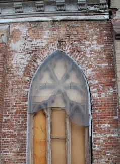
Effects of differential settlement.
attack (rot). Wood destroying fungi ‘eat away’ at the wood cell structure, causing severe deterioration that can result in a significant loss of cross-section, change in mechanical properties, and a significant decrease in strength. This deterioration can lead to crushing of the wood fibers, pile failures, and localized or global differential settlement of the superstructure. If the deterioration is minimal or caught early, the piles may be able to be salvaged if the groundwater elevation can be restored and maintained to a level above the tops of the piles. This is typically accomplished by re-charging the groundwater to raise the water surface, installing coffer dams that surround the building footprint, etc. If the deterioration is too advanced, underpinning and re-supporting the building structure is typically required. The difficulty, of course, is that evaluating the condition and understanding the magnitude of the problem is often a difficult and expensive proposition: extrapolations of remaining service-life
Attention Bentley Users
Have you received your automatic quarterly invoice from Bentley? Would you like to reduce or eliminate these invoices? Use SofTrack to control and manage Calendar Hour usage of your Bentley SELECT Open Trust Licensing. Call us today, 866 372 8991 or visit us
www.softwaremetering.com
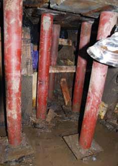
Cut and post underpinning method.
predictions often need to be made based on a very small sample size (limited number of test pits), yet the variability in damage amongst the population can be significant. Typical remedial approaches include either adding new pile elements (essentially circumventing the existing piles), or the cut-and-post method (underpinning). The cut-and-post method involves removal of the deteriorated tops of the piles, and replacement with concrete-filled steel posts wedged to the underside of the foundation or pile cap. When a group of piles is cut and posted, excavation is then filled with concrete to create a new cap and to fully encase the steel posts (therefore making the whole system less susceptible to water fluctuations). Planning and phasing of this approach is critical, especially for columns where temporary supports may need to be provided (especially if only a few piles support the entire column cap). Adding supplemental piles to the perimeter walls is an effective option in lieu of underpinning. There are numerous pile options available: push-pier, helical, micro-piles, etc. Several items need to be considered when providing supplemental elements to the existing system. First, whenever possible, piles should be added to both sides of the walls to avoid eccentricity issues. Second, the most challenging part of adding supplemental piles to masonry foundation walls is usually attaching the piles to the walls to be able to transfer the loads into the new system. This can be accomplished in several ways. One way is to place piles opposite each other adjacent to the wall, and to construct a connecting grade (needle) beam under the wall to transfer the load from the wall to the piles. However, this requires
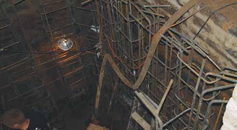
Supplemental piles.
extensive excavation and coordination with existing pile locations. Another option is to install the piles on opposite faces of the wall, to construct concrete caps atop each pile, and then install rods through the existing wall to each cap. The rods are then post-tensioned to “clamp” onto the existing wall to transfer the wall loads to the piles. For smaller loads, specialty or bolted brackets can be used to attach the piles to the wall. If none of these options work, independent foundations can be installed to support new structural framing to carry the increased loads Distress to the structure can also be due to eccentrically loaded existing piles. The crude historic methods used to install timber piles can result in piles not being in the proper locations. Eccentrically placed and loaded piles along perimeter walls, and especially at interior column pile caps, can cause distress and problems in service. The eccentric loading can cause rotation of the pile caps and leaning of the columns or walls extending up from the cap. The eccentricity can be addressed by adding piles to the cap in a similar manner as described above. Replacing the pile cap below a column may also be necessary in some situations, which can be extremely difficult. This typically requires that the column load be temporarily removed so that the cap can be removed and replaced. Extensive shoring, jacking, and monitoring is often needed to accomplish this, and can be prohibitively expensive. Supplementing the existing piles and maintaining the existing cap should be the first option considered. In some instances, timber grillages (horizontal timbers) were placed over the tops of piles during original construction to provide a flat surface to lay the base course of masonry. Grillages act as continuous beams to transfer loads from the masonry to the piles. As building loads are transferred through the timber grillage to the piles, the timber is loaded perpendicular to the direction of the grain. However, due to its cellular structure, wood is weak in the perpendicular-to-grain direction and may be inadequate to resist such loading. This weakness, combined with the relatively high concentrated loads at the piles, can lead to local crushing of the timber grillage and settlement of the structure. Timber grillage that is placed eccentric to the pile tops can cause further crushing and splitting of the wood, leading to larger localized displacements. The cut-and-post method of underpinning alleviates this condition as the tops of the piles and timber grillage are removed.
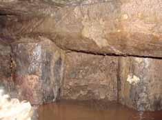
Increased Loading
Renovations can often add load to the building foundations due to increased weight of finishes, additional proposed occupancy loads, addition of HVAC systems, and many other items that can be part of a typical renovation project. Accounting for and assessing how these additional loads affect the existing foundations, especially those featuring timber piles, can be difficult. Due to their age, there are often no available building plans, as-built documentation, or pile-installation records for historic houses of worship. However, expensive investigations to determine the type, layout, configuration,
and then capacity (through testing, analyses, etc.) of the existing foundations may not be needed, depending on the projected load increase. A reasonable rule of thumb, supplemented by engineering judgment and other considerations, is to take no further action if the additional building loads increase the foundation loads by less than 5%. For load increases above 5%, and in some cases up to 10%, determining the existing foundation layout and capacity is needed. This may require a potentially significant investigative effort: in-situ testing of stone or masonry, probing and sampling for subsequent testing, test pits to expose foundations, evaluation of support and soil conditions, soil and other testing, additional analyses, etc. If pile foundations are involved, typical size and configuration of the piles needs to be documented as well. A load test may also be prudent to ensure that the piles have sufficient capacity and that the increased loading (or suspected deterioration) will not cause settlement of the structure or other distress. Load tests on existing piles should be performed on piles along the perimeter walls, where the weight of the masonry wall above can be used as a reaction load. Typically, one of the piles exposed in the test pit is selected for the test. The top of the pile is removed so that a hydraulic jack can be installed and wedged between the pile and the underside of the wall. The jack is then used to load the pile in increments up to and beyond the current pile load, and the pile displacement is measured. The load and displacement measurements are recorded and evaluated, in a similar manner to any other pile load test, to determine an allowable capacity for the piles. Often, the existing foundation systems will not have any reserve capacity, and adding new loads to the building will require supplemental foundations. A number of effective options, some described above, can be used to achieve greater foundation capacity: wall or column strengthening, underpinning, increasing the bearing area, adding supplemental components (or piles), etc.
Conclusion
Foundations are a critical part of any building. Problems with foundations, if not addressed, will almost invariably affect the superstructure, often in significant and irreversible ways. Understanding existing conditions, limitations, and expected in-service behavior of the foundation systems is especially important in historic structures such as houses of worship, and are a key to success for any renovation or restoration project.▪

State-of-the-Art Products
STRUCTURAL TECHNOLOGIES provides a wide range of custom designed systems which restore and enhance the load-carrying capacity of reinforced concrete and other structure types, including masonry, timber and steel. Our products can be used stand-alone or in combination to solve complex structural challenges.
V-Wrap™
Carbon Fiber System
DUCON®
Micro-Reinforced Concrete Systems
VSL
External Post-Tensioning Systems
Tstrata™
Enlargement Systems
Engineered Solutions
Our team integrates with engineers and owners to produce high value, low impact solutions for repair and retro t of existing structures. We provide comprehensive technical support services including feasibility, preliminary product design, speci cation support, and construction budgets. Contact us today for assistance with your project needs.
www.structuraltechnologies.com +1-410-859-6539
To learn more about Structural Group companies visit www.structuralgroup.com DUCON® trade names and patents are owned by DUCON GmbH and are distributed exclusively in North America by STRUCTURAL TECHNOLOGIES for strengthening and force protection applications. VSL is the registered trademark of VSL International Ltd.
REACHING NEW HEIGHTS

IN LOS ANGELES
By Gerard M. Nieblas, S.E., LEED AP
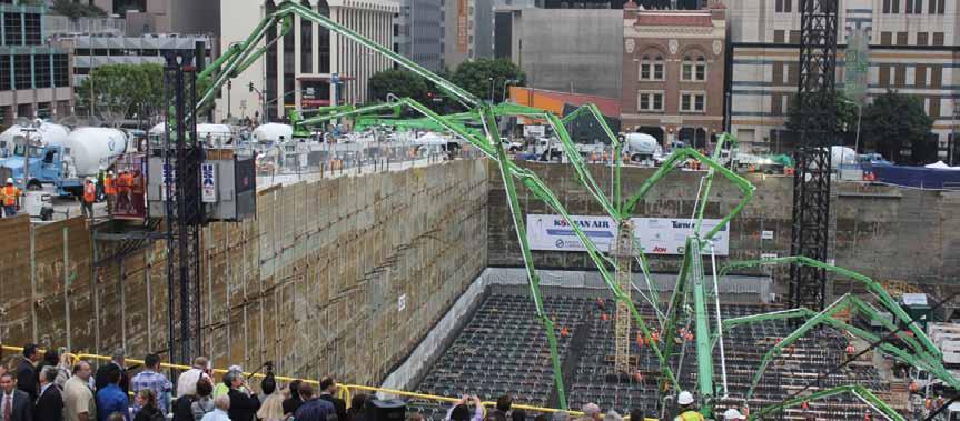
Th e grand pour (Guinness World Record).
The skies above downtown Los Angeles will see a new high rise offi ce/hotel building by March of 2017. Rising out of a 90-foot deep excavation in the earth, the building will dominate the skyline of Los Angeles. Th e Wilshire Grand project takes up an entire city block. Th e site is bounded by Wilshire Boulevard and Francisco to the north, and 7th Street and Figueroa to the south.
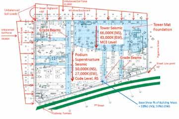
Unbalanced soil loads.
Project Description
Th e project is approximately 2,000,000 square feet with 900 hotel rooms, 400,000 square feet of offi ce space and 45,000 square feet of retail space. Th e fi ve-level subterranean parking covers the entire site and will accommodate 1,100 vehicles. Th e structure will have a rooftop pool with ocean views, highly advanced pressurized double decker elevators, an architectural roof top sail and a 200-foot tall architectural spire. Th e Tower structure is 73 stories, with the lower fl oors comprised of offi ce space and the upper 40 fl oors as hotel rooms. Th e lateral system for the building is a concrete core wall with concrete fi lled steel box columns and structural steel framing outside the footprint of the core. Th e lateral system of the Tower is extremely slender, with a 30-foot wide core wall in the transverse building direction and nearly 1,000 feet tall. Along the height of the structure there are buckling restrained braced frames to reduce the overturning demands of the core wall on the mat foundation and to stiff en the structure for transverse wind and seismic drift. In order to meet the aggressive schedule, the project is fast track. Th e building permits were issued as Foundation Only, Foundation +, Superstructure part A to the 26th fl oor, and a “Building Permit Set” to the 73rd fl oor.
The upper 40 floors of the Tower are hotel rooms. To maximize views for all the rooms, it was architecturally important to provide floor to ceiling glass. A conventional code design of this structure would have required a secondary lateral system along with the core wall design. This system would have been some type of steel frame with deep members around the perimeter of the structure where views of the Pacific Ocean were most valued. The design team selected Performance Based design to eliminate this second lateral “back up” system. A secondary benefit to the Performance Based Design allowed the design team, along with the owner and the peer review panel, to set the performance objectives for the structure. Len Joseph with Thornton Tomasetti provided invaluable consulting on the performance based design of the Tower and its interaction with the podium structure.
Unbalanced Site Loads
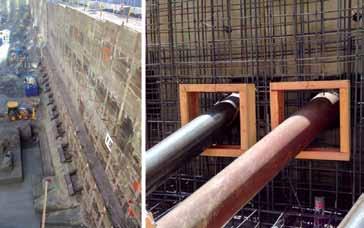
The northwest corner of the site is 39 feet higher than the southwest corner of the site. This unbalanced soil load results in an unbalanced horizontal force of approximately 25,000,000 pounds. This unbalanced force is approximately 80% of the base shear of the Podium superstructure and approximately 50% of the Tower base shear. In the east west direction, this unbalanced soil force accounts for 23% of the total base shear of the entire project. The addition of interior basement walls and fin walls off the core walls are required to resist these additional horizontal soil forces. These supplemental basement walls are supported on grade beams as large as 18 feet wide and 12 feet thick, with over 1 million pounds of reinforcing steel.
Shoring
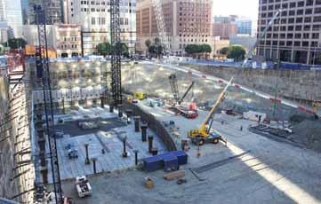
The excavation for the site encompassed an entire city block. There are 316 soldier piles around the perimeter of the excavation. The excavation along 7th Street is as close as 5 feet from the subway tunnel. To provide additional stiffness in the shoring system, rakers were added at 8 feet on center along 7th Street, adjacent to the subway tunnel. The x, y and z coordinates of the tunnel along the length of the excavation are monitored on a daily basis. This will continue until the entire podium structure reaches street level. Because of the removal of the soil adjacent to the tunnel, it has moved vertically approximately ½-inch.
Lateral Foundation Analysis
The Tower mat foundation was designed for two levels of earthquake resistance, as well as a 1,700 year wind event. The tower was designed for MCE (the Maximum Considered Earthquake – 2% probability of exceedance in 50 years, or 2,475 year return period) site specific response spectra utilizing several damping values, and for the SLDE (Service Level Design Earthquake – 50% probability of exceedance in 30 years, or 43 year return period) site specific response spectra utilizing several damping values. The SLDE earthquake design values were typically 15-20% of the corresponding MCE values. The Tower was designed for a suite of eleven time histories utilizing a Non-Linear Time History Analysis provided by our consultant, Thornton Tomasetti. continued on next page
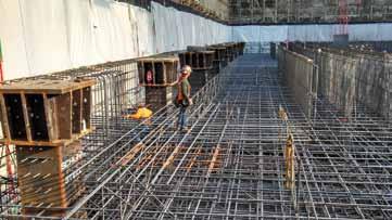
Mat reinforcing with shear reinforcing.
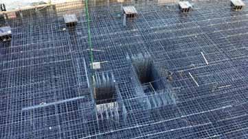
Elevator pits before top of mat reinforcing.
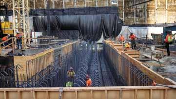
Grade beam with one million pounds of reinforcing.
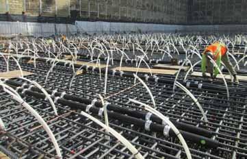
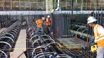
Vibrating the mat pour.
The Podium structure and basement were designed for the prescriptive requirements of the 2010 California Building Code and ASCE 7-05 with a response spectra analysis. The interaction of the Tower structure with the podium structure and the framed parking levels was worked out by comparison of relative rigidities of each structure between Brandow & Johnson Inc. and Thornton Tomasetti.
Tower Foundation
The foundations for the project are supported on bedrock. The allowable bearing pressures for sustained vertical loads under Allowable Stress Design were 12 ksf and 30 ksf for transient loads at localized areas from wind and seismic forces. The ultimate soil bearing pressure was 90 ksf for localized transient loads under the MCE design event. The footprint of the mat foundation extends past the outside of the Tower to reduce bearing pressures under the mat, and provide more stability for the foundation. Under service loads, the average net bearing pressure under the mat is 12 ksf. Under the maximum considered earthquake (2,475 year return period) the bearing pressures are as high as 58 ksf in small localized areas. The vertical loads from the core wall and the applied loads on the mat foundation are so great that it is anticipated that the 18-foot thick mat will dish approximately 1 inch under the weight of the core wall, and the mat will settle approximately 2 inches from the weight of the tower. The foundation for the Tower was poured in mid-February of 2014. It set a Guinness Book world record for the largest continuous concrete pour in history. The USC Marching Band led the first concrete truck. In total, 21,200 cubic yards of concrete were poured in 18.5 hours between Friday night and Saturday morning. The mat pour was 17 feet - 6 inches thick and had 6.7 million pounds of reinforcing steel. The original reinforcing in the bottom of the mat was 13 layers of #11 @ 6-inch on center each way. The reinforcing steel subcontractor was concerned about placing these bars and threading the headed #9 shear reinforcing through a clear space of 4½ inches. To alleviate this congestion, #18 bars with couplers were utilized. The bottom mat reinforcing was modified to 13 layers of #18 bars at an average of 15-inch on center. Since #18 bars may not be lapped spliced, mechanical couplers were utilized to join the bars. Each of these bars had to be hand spun onto the coupler and tightened with a torque wrench. In the top of the mat are 4 layers of #11 bars at 12-inch on center. To reduce the amount of reinforcing required, grade 75 ksi steel was utilized throughout the mat foundation. In the center portion of the mat, bars were spaced at 4 feet on center max in each direction for temperature expansion and contraction, and to provide support for the cooling pipe.
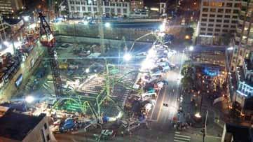
Night time photo of grand pour.
Mat
Concrete Temperatures
The heat of hydration was so great due to one continuous pour, the concrete temperatures were predicted to exceed 160 degrees without mitigation. To combat this, an active cooling system with on-site cooling towers was provided. Approximately 2,000 vertical loops of ¾-inch PEX pipe were manifolded together to remove heat from the concrete. This cooling system was left in place for two weeks for continued heat removal. Another concern with the temperature of the concrete was the differential temperature from the interior to the exterior of the mat. We were limited to a maximum 35 degree temperature differential from the exterior edge to the core of the mat. In order to keep the extreme edges of the concrete from “catching cold”, thermal insulation was added on the top of the mat to keep the concrete warm. This thermal insulation was left in place for two weeks. The Contractor waited patiently for two weeks to get on the mat to start forming the core wall. Core Wall The concrete shear walls at the base of the structure are 48 inches thick and heat of hydration was always a concern for the design team. Initially it was planned to build a mockup of the 48-inch wall, with thermocouples to monitor temperature and reinforcing to model congested areas of the walls. Due to the nature of the schedule, time did not allow for a mockup. To provide the design team with a level of comfort, the Contractor retained a concrete expert from Illinois. Computer models were made to simulate the heat of hydration, and the concrete mix and cement were analyzed. It was determined that the core wall concrete was DEF (Delayed Ettringite Formation) susceptible. DEF is a type of internal sulfate attack on concrete. In order for DEF to be an issue, three things need to be present: • Unfavorable Cement Chemistry – 12% fly ash in the concrete and unfavorable cement chemistry. • Long Term exposure to water – concrete core wall exposed to the elements for 1½ to 2 years. • Temperatures over 160 degrees – with a large amount of cement in the mix, a great deal of heat of hydration, and warm summer temperatures in Los Angeles, this was an issue.
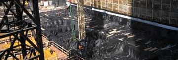

First lift of corewall reinforcing. To avoid DEF, it was necessary to chill the concrete mix so that concrete temperatures would never exceed 160 degrees. Los Angeles had numerous days where the ambient air temperature has exceed 100 degrees. Typically concrete can be delivered at point of placement as warm as 90 degrees; to avoid DEF, concrete delivery temperatures were limited to 70-75 degrees. The reduced concrete delivery temperature retarded the mix from maturity, which complicates the 4-day cycle of the concrete core wall. The Contractor’s schedule requires that the form system be jumped 12 hours after the pour. With lower delivery temperatures of concrete and slower maturity, the concrete is reaching approximately 1,000 psi at 12 hours. It was initially assumed that the concrete would reach 2,500 PSI at 12 hours. This created schedule problems with the coil inserts utilized in the core wall to jump the form system. Currently, test protocols are under development to demonstrate a safety factor of 3 in the design loads of the form system for 1,000 psi concrete.
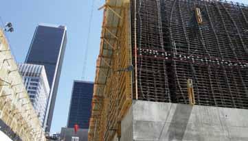
Typical corewall reinforcing.
Conclusion
The Wilshire Grand Hotel/Office building will continue rising from the ground over the next three years. In late 2015 the structure should top out, with the remaining time devoted to the completion of the architecture and building skin. This will be the tallest structure west of the Mississippi. Outside of New York and Chicago, it will be the tallest structure in the United States. It will be the only highrise building in Los Angeles without a flat roof top, redefining the Los Angeles skyline with its elegant sail atop the structure.▪
Gerard M. Nieblas, S.E., LEED AP, is President of Brandow & Johnston Inc. Gerard may be reached at gnieblas@bjsce.com.
ADVERTISEMENT–For Advertiser Information, visit www.STRUCTUREmag.org
Helical Pile Technology
Exclusive Patented Technologies for Foundation Solutions
ESR-1854
ICC-ES Recognized as Code Compliant to meet International Building Code
Patented threaded connection provides a higher torque rating to penetrate dense soils; Rigid connections to maximize lateral capacity

Up to six different pile diameters in stock to provide the most economical solution to meet any design load

Custom fabrication of piles & brackets for residential, commercial, industrial, and utility solutions


Watch Our Helical Installation Video: ramjack.com/HelicalPiles 888.332.9909


Patented threaded connection; Strongest, most rigid in industry
Thermoplastic Helical Piles resist corrosion/ environmentally friendly
Helical Piles stamped into true spiral shape; Penetrates load- bearing strata
Geopier is Ground improvement.™

Work with engineers worldwide to solve your ground improvement challenges.
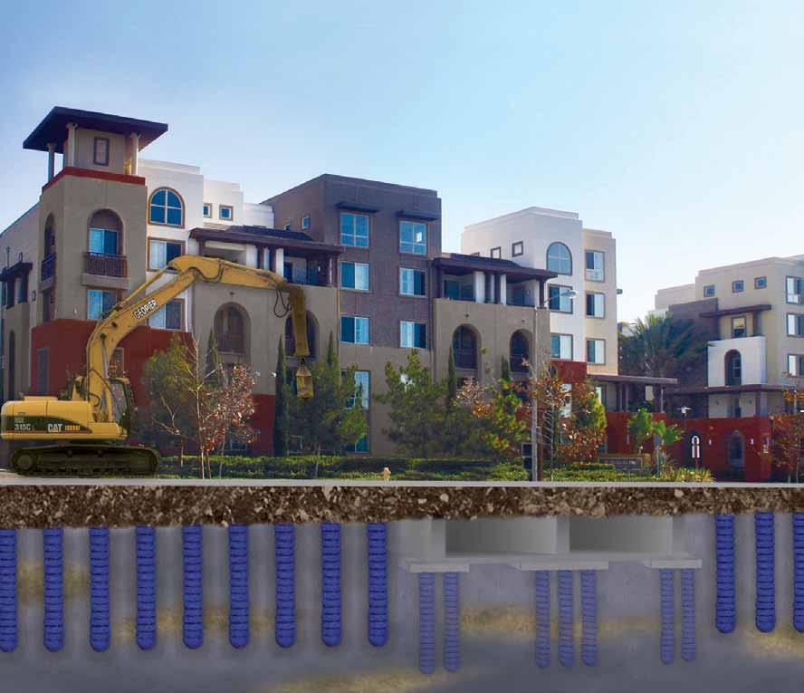
the Geopier Gp3® system: controllinG settlement
we help you fix bad Ground.
For more information call 800-371-7470, e-mail info@geopier.com or visit geopier.com.
Plans for the 150,000 square foot Avalon Irvine apartment complex in Irvine, CA featured a common “wrap” style structure, with 4-story apartments surrounding a 4.5-story parking garage. The site was underlain by 20 to 25 feet of soft to medium stiff lean clay with groundwater encountered at depths of 8 to 10 feet. The clay was underlain by stiff clay and dense sand to a depth of 50 feet. Reconciling the settlement tolerances between the apartments and the parking structure presented a unique design challenge. The GP3® system was an ideal solution, meeting the specified settlement tolerance for 1” total foundation settlement and ½ inch differential between the parking structure and the apartments. By reducing total settlements and accelerating time rate of settlement for all structures, GP3 eliminated the need for a 6-9 month surcharge.
Shoring Up the Past New York CitY Style By Alan M. Rosa, P.E. and Stephen Lehigh
The design of temporary shoring for existing buildings offers the engineer challenges on multiple levels, especially on vintage structures in New York City when not all the existing conditions can be known. This article presents a project that involved temporary shoring at the second floor of approximately ninety feet of exterior bearing wall and storefront of a depression-era six-story apartment building located on a busy intersection in midtown Manhattan. The building was continuously occupied during shoring operations. The design included an innovative rigid support of an excavation system designed for removal of existing foundation walls, and support of temporary shoring systems. The project, located at the corner of East 63rd Street and 3rd Avenue, is part of the construction of a new Metropolitan Transit Authority (MTA) 2nd Avenue Subway Line project. This building will serve as a new entrance to the 63rd Street/Lexington Avenue Station by way of a newly installed escalator entry.
Proposed Construction
The proposed permanent design creates access to the lower level of the subway station adjacent to the building using an escalator at the northwest corner of the building. The access point exits at street level within the envelope of the existing apartment building. During the construction of the new entrance, the building will receive a new reinforced concrete foundation wall that will replace an existing stone rubble wall. The masonry bearing walls and the existing storefront above the street level will be replaced with a new perimeter steel support frame. The new foundation will include a reinforced concrete slab, at approximately the same elevation of the existing basement, that will ramp down fifteen feet below the basement level for the new escalator.
Existing Building Construction
Typical multi-story residential construction of this era consisted of wood floor framing, masonry bearing walls, and perimeter steel storefront framing. The estimated temporary shoring loads of this project at the second level varied from 8 kips per foot (kips/ft) to approximately 13 kips/ft of wall. The foundation consisted of mortared stone rubble foundation walls, with brick masonry piers at existing column locations within the basement. The interior of the building is supported by steel beams and columns on spread footings.
Support of Excavation
A rigid support was required for both the support of the temporary shoring frames needed upon removal of the existing rubble foundation walls and for the deep excavation system below the basement level. Conventional methods were not possible due the proximity of the street to the building and the vast amount of existing street utilities. The supports of the excavation were required to be installed prior
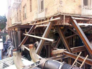
Figure 1. Elevation of temporary shoring system at north storefront and bearing wall.
to any demolition, and their sequences were limited to occur after installation and preloading of the temporary support steel. A system utilizing eight 5-foot, 6-inch x 5-foot, 6-inch post-tensioned unreinforced concrete piers spaced at 9 feet on centers was developed. Hand excavated pits were advanced using horizontal sheeted timber rings forming a box, similar to conventional underpinning methods. The base of each pier was extended below the bottom of the proposed excavation to an adequate subgrade bearing strata. Once the concrete was poured and cured, the tops of the piers were post-tensioned using self-drilled rock anchors installed at a 1:4 slope to accommodate the proximity of the existing building foundation (Figure 1). The steeply sloped tiebacks were also advantageous to avoid the existing street utilities. The anchors were located at the center of the piers in a Polyvinyl Chloride (PVC) sleeve within the pier, and grouted into ledge rock. The embedment into rock ranged from twelve to fifteen feet and each tieback was tested to 133% of the anticipated 240 kip lock-off load, i.e. the design anchor load at the tallest pier. At the northwest corner of the building, the existing adjacent below grade station entrance framing was used for support of the temporary shoring system.
Temporary Shoring
The existing building is classified by the MTA as a fragile structure, defined as the limit of damage allowed is no more than very slight. This is defined as damage that contains fine cracks (up to 1/32 inch wide) in the exterior wall façade that are easily treatable and damage that is generally limited to interior wall finishes. The restrictions for the temporary shoring requirements were many, and included stringent tolerances on the maximum and relative movement. A maximum limit of 1/8 inch, with a threshold limit of 1/16 inch in both the horizontal and vertical directions, was required. Of the variety of temporary shoring designs required on this project, including one for removal of a six story steel interior column, the two main systems discussed in this article will be one for the support of the existing perimeter beams over the storefront and another for the support of the existing brick bearing walls. At Storefronts Within the limits of the new entry, the existing structure was demolished up to the underside of the existing steel beams that support
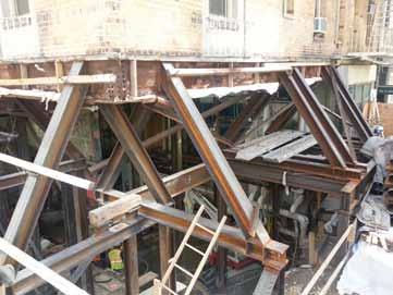
Figure 2. Typical A-Frame shoring at storefronts.
the masonry above and span the storefronts. Thus, any temporary shoring system must leave clearance for the installation of new perimeter beams and columns installed directly below the existing second floor perimeter steel framing. In addition, a system was required to allow the installation of a new concrete foundation wall to replace the existing rubble foundation wall. An A-Frame system consisting of compression struts and tension ties was developed (Figure 2). The exterior ends of the frames were supported on the post-tensioned concrete piers, and the interior ends of the frame were supported on a steel frame system which in turn was supported on 3-foot by 4-foot concrete piers to a depth of approximately thirty feet below
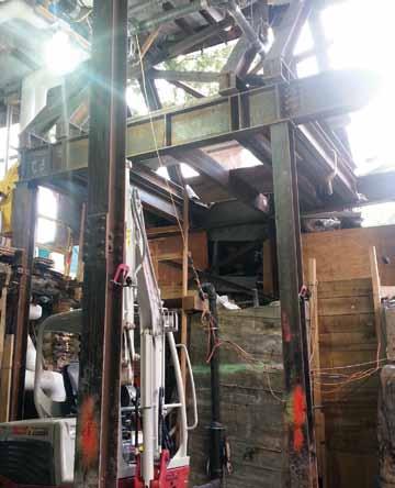
Figure 3. Elevation of northwest corner with post-tensioned pier supporting the A-Frames.
ADVERTISEMENT–For Advertiser Information, visit www.STRUCTUREmag.org
the street level (Figure 3). The tops of the A-Frames were attached not practical given the various frame deflections required to preload directly to the existing steel beams by welding the compression the system. It was therefore determined that the best approach was struts to the existing girder (Figure 4, page 28). The frames straddled to wedge-shim each needle beam at each end to the required vertical the existing beam ends above the existing columns that were being displacement and then to pack it with flat shims to provide uniform removed so as to not change the existing support conditions of the bearing support. The required displacement was determined from beams; that is, one A-Frame at each beam end. The A-Frames were an estimate of the uniform wall load and the tributary width of an preloaded using hydraulic jacks at each side on the frame. The jacks individual needle beam. In order to account for deformations in the were supported by channels connected to the main temporary girders piers and the steel columns, and the deflections of the supporting just below the tension members of the frames. At other locations, frames, a comprehensive structural analysis was performed on both it was possible to jack only from one side of the A-Frame. In these the interior and exterior frames to determine the exact level of shims cases, the lateral movement of the frames at the apex due to the required for each needle beam. Shimming could not commence one-sided jacking was determined to be negligible. Jacking loads until the entire web space and the top flange was packed with grout were limited to ninety percent of the calculated dead load plus a so that the masonry bearing area was increased and the masonry small allowance for live load throughout the building. Since each frame was jacked independently, the expectation was that little to no vertical movement would occur due to the restraint provided by the existing brick walls. Thus, it was important that the jacking loads be determined as precisely as possible, and that the A-Frames and supporting system The Industry Leader in Seismic And Wind Solutions. would have a significant amount of extra strength available to confidently remove the existing steel columns supporting the perimeter storefront steel. Monitoring systems were installed to register any movements. As a result, all original building columns were removed successfully without any appreciable movement measured or cracking observed. At Bearing Walls Along East 63rd Street, a thirty-eight foot long section of an existing 16-inch thick brick masonry bearing wall was required to be removed to the same elevation as the adjacent storefront (Figure 5, page 28). Needle beams spaced at two feet on centers, on average, were utilized. As in the case of the A-Frames, the interior ends of the beams were supported on the steel frames, which in turn were supported on the 3-foot by 4-foot concrete piers. The exterior frames were supHardy Frame® Special Moment Frame ADVERTISEMENT–For Advertiser Information, visit www.STRUCTUREmag.org ported on the post-tensioned concrete piers (Figure 4). At the second floor, there were four existing steel beams supported by the existing bearing wall that needed to be shored prior to wall removal. Hung beams adjacent to the wall being removed provided the support of the existing beams and were attached to the bottom flanges of the needle beams. Distribution beams adjacent and parallel to the exterior wall were required at hardyframe.com 800 754.3030 • uspconnectors.com 800 328.5934 the larger window openings, and at the existing fire escapes, to evenly distribute the wall load to all needle beams (Figure 6, page 28). In order to uniformly load ©2014 MiTek, All Rights Reserved the existing wall, jacking methods were


Figure 4. Typical A-Frame and needle beam construction sections at existing storefront and bearing wall.
Figure 5. Post-tensioned concrete pier construction.
was not overstressed (Figure 6). Concrete piers were monitored for settlement during shimming operations, with the understanding that the required design shim thicknesses may need to be adjusted if settlement occurred. The heaviest loaded needle beams were shimmed to an estimated mid-span concentrated load of 24 kips. Once completed, the masonry wall was removed in sections starting directly under the bottom flanges of the needle beams. Removal was completed within two days with no movement or cracking registered.
Monitoring
One of the more important aspects of this temporary support design was the monitoring of the existing building for displacement and rotation. With close monitoring and tight restrictions given for movement and rotation, it allowed adjustments to the design if unintended movements occur. Therefore, the implementation of a sound, well thought out monitoring program was an important design consideration for
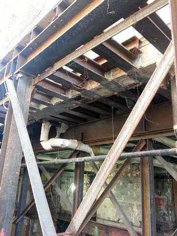
Figure 6. Needle beam support at existing masonry bearing wall with window distribution beam.
this project. On this project, multiple prisms and rotational meters were strategically placed at the face of each building elevation. All instruments were measured continuously from a remote location. The tops of the post-tensioned concrete piers were monitored during preloading of the A-Frames and the needle beams, in anticipation of possible settlements and possible horizontal displacements due to relaxation of the post-tensioning anchors. Monitoring will extend to the end of construction.
Conclusion
The design of temporary shoring systems in New York City offers the engineer many challenges given special constraints, existing utilities and unknown conditions. Innovative, yet practical solutions are necessary to achieve the desired result, one that is cost effective and on time. A sound monitoring program is an essential part of the temporary shoring design and construction.▪
Acknowledgment: Contractor – Judlau Contracting, Inc., College Point, NY
Alan M. Rosa, P.E. (arosa@scs-pc.com), is a Principal and Stephen Lehigh (slehigh@scs-pc.com), is a Senior Project Structural Engineer at Structural Consulting Services, P.C., Brookfield, CT.
Excellence in Structural Engineering
NCSEA 17th Annual Awards Program
The National Council of Structural Engineers Associations (NCSEA) is pleased to announce the following 2014 Excellence in Structural Engineering Awards. The awards were presented on the evening of September 19 during the Awards Program at NCSEA’s 22nd Annual Conference in New Orleans, LA. The awards have been given annually since 1998 and highlight some of the best examples of structural ingenuity throughout the world. All structures must have been completed, or substantially completed, within the past three calendar years. Awards were given in eight separate categories, with one project in each category being named the Outstanding Project. The categories for 2014 were: • New Buildings under $10 Million • New Buildings $10 Million to $30 Million • New Buildings $30 Million to $100 Million • New Buildings over $100 Million • New Bridge and Transportation Structures • International Structures over $100 Million • Forensic / Renovation / Retrofit / Rehabilitation Structures • Other Structures The 2014 Awards Committee was chaired by Carrie Johnson (Wallace Engineering Structural Consultants, Inc., Tulsa OK). Ms. Johnson noted: “We had a great group of judges from the Structural Engineers Association of Oregon this year, and some truly outstanding projects. They had the enormous task of evaluating a wide variety of projects from twenty different states and five different countries. The judges did an outstanding job of thoroughly analyzing each entry and thoughtfully discussing which ones should receive an award. Seeing the entries each year continues to make me proud to be a structural engineer.” Please join STRUCTURE® magazine and NCSEA in congratulating all of the winners. More in-depth articles on several of the 2014 winners will appear in the Spotlight Department of the magazine over the course of the 2015 editorial year.
2014 PANEl of JudgES
The judging was held Tuesday July 22, 2014 at the offices of KPFF in Portland, OR. The 2014 awards jury from the Structural Engineers Association of Oregon included the following individuals:
Rick Amodeo, P.E., S.E. AAI Engineers Joe Gehlen, P.E., S.E. Kramer Gehlen & Associates, Inc. Ron Kernan, P.E., S.E. KPFF Consulting Engineers Amit Kumar, P.E., S.E. City of Portland Mark Libby, P.E. HDR Engineering Brad Moyes, P.E., S.E. KPFF Consulting Engineers Trent Nagele, P.E., S.E. VLMK Ed Quesenberry, P.E., S.E. Equilibrium Engineers, LLC Tim Rippey, P.E., S.E. Tim Rippey Consulting Engineers Wade Younie, P.E., S.E. DCI Engineers
Category 1 New Buildings under $10 Million outStANdiNg ProJECt
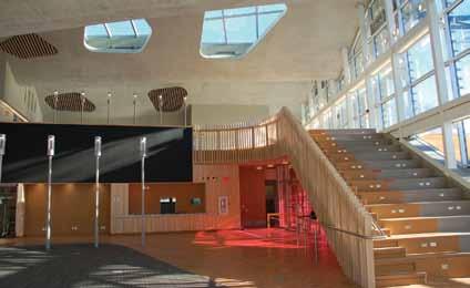
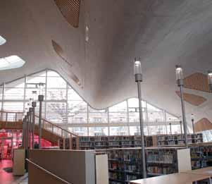
Jasper Place Library
Edmonton, Alberta fast + Epp
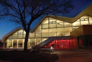
Jasper Place Library is a 15,000 square foot replacement of an existing facility. The striking new structure was built with the goal of becoming the new social heart in an older suburban neighborhood. Predominantly cast-in-place concrete on piles, the primary feature is the expressive curved plate concrete roof that spans the entire library space, punctuated with skylights. The overall result is a response to the changing needs of the Library of the Future.
Courtesy of Stephan Pasche.
Courtesy of Stephan Pasche.
Category 2 New Buildings $10 Million to $30 Million outStANdiNg ProJECt
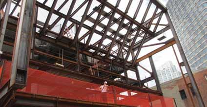
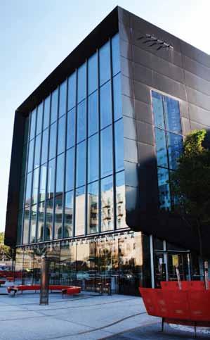
Theatre for a New Audience at Polonsky Shakespeare Center
Brooklyn, NY robert Silman Associates The Theatre for a New Audience is a laboratory for modern theatrical interpretation of classical plays. Its new home, a sleek glass and steel building in Brooklyn’s BAM Cultural District, is deceptively simple in form, belying its structural complexity and the intricate acoustical isolation that prevents the sounds of the subway running underneath and the traffic on the busy streets around it from interfering with the performances happening within. A cantilevered front façade allows the entire front lobby of the theater to hover above the plaza below, rather like a curtain being raised for a performance.
Category 3 New Buildings $30 Million to $100 Million outStANdiNg ProJECt
P750 Helicopter Maintenance Hangar
San diego, CA frankfurt Short Bruza Associates, PC
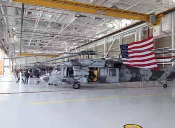
The U.S. Navy required a three squadron helicopter maintenance facility located along the northern waterfront at Naval Air Station North Island. With prime inward views throughout San Diego, this hangar had to be worthy of its location, reflect an equally positive image, become a significant part of the installation’s waterfront and a source of Navy pride. Structural engineers collaborated with the project team to deliver strong aesthetic solutions to the project’s numerous physical challenges including clear space, volume, environmental design factors and client requirements. This 112,000 square foot facility was successfully completed at an approximate cost of $50 million.
Category 4 New Buildings over $100 Million outStANdiNg ProJECt

Newport Beach Civic Center and Park
Newport Beach, CA Arup
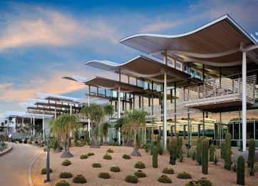
The conceptual vision of architectural firm Bohlin Cywinski Jackson paired with the sculpted steel designed by Arup structural engineers celebrates the use of exposed structural steel as architectural form and function. New structures include the City Hall, Community Room, Council Chambers, expansion to the public library, parking garage, and four pedestrian bridges. The iconic curved wide-flange waved roofs, vierendeel trusses, and buckling restrained brace frames of the City Hall, and the large cantilevers of the Library roof and the San Miguel Bridge, allow the public to see the structure “at work” while providing memorable experiences.
Courtesy of David Wakely. Courtesy of Heliphoto.net.

Category 5 international Structures over $100 Million outStANdiNg ProJECt
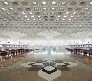
Mumbai, india Skidmore, owings & Merrill llP Chhatrapati Shivaji International Airport Terminal 2 adds 4.4 million square feet of new space to accommodate 40 million passengers per year. The primary design feature of the building is a long-span roof covering a total of 70,000m2 (83,720 square yards) over various functional requirements, making it one of the largest roofs in the world without an expansion joint. The Headhouse Roof, supported by only 30 columns, produces a large column-free space ideal for an airport. The Terminal Building also includes the largest and longest cable wall system in the world. The structural design prioritized modular construction for economy and facilitation of an accelerated construction schedule.
Courtesy of GVK.
Courtesy of Robert Polidori | Mumbai International Airport Pvt. Ltd.

Category 6 New Bridges and transportation Structures outStANdiNg ProJECt
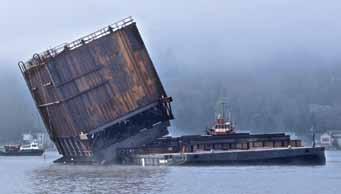
Floating Cofferdam for Repair of the Washington State SR-520 Floating Replacement Bridge
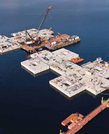
Seattle, WA Ben C. gerwick inc. Structural cracking in the new pontoons for the replacement SR-520 floating bridge required repair in a dry environment. A floating cofferdam was designed to act as a floating dry dock that seals against a bridge pontoon afloat. The cofferdam features two sliding side gates, a cofferdam-pontoon seal, and 28 struts with hydraulic jacks for load transfer. It is 96 feet wide, 44 feet long and 35.5 feet tall with a weight of 600 tons. The cofferdam was fabricated on a barge and side launched at the Lake Washington site.
Category 7 forensic/renovation/retrofit/rehabilitation Structures outStANdiNg ProJECt
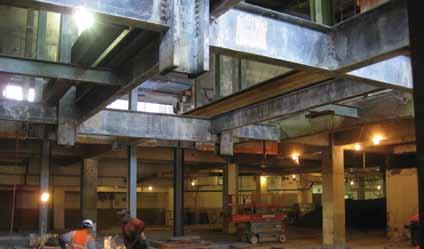
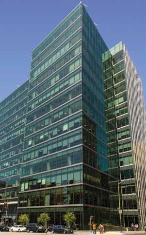
680 Folsom Street
San francisco, CA tipping Mar
The transformation of 680 Folsom – a 1960s steel-moment-framed building that no one had wanted – into desirable office space involved a complete gut renovation, seismic retrofit, and expansion. At the behest of TMG Partners, a value-engineering effort impelled Tipping Mar to once again boldly innovate, reaching centuries into the past and oceans away to medieval Japan. The result? A unique isolative lateral system – unprecedented in modern engineering – that saved $4 million on a $110 million project and provided enhanced seismic performance.
Category 8 other Structures outStANdiNg ProJECt
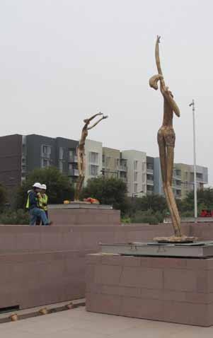
East Station Plaza – Danseurs (Dancers)
union City, CA Simpson gumpertz & Heger inc.
The City of Union City, California sought to develop a civic plaza, which included a centerpiece – a terraced fountain with three bronze sculpture “Danseurs” on platforms positioned within the fountain. The fountain would be built 0.6 miles northeast from the Hayward fault line. With that in mind, Simpson Gumpertz & Heger suggested mounting the sculptures on base-isolated platforms – put them on a suspension with springs and shocks to reduce the lateral forces on the sculptures. Using isolated platforms, the architect and city were provided with an elegant solution to protecting their civic sculptures from earthquake damage for future generations.

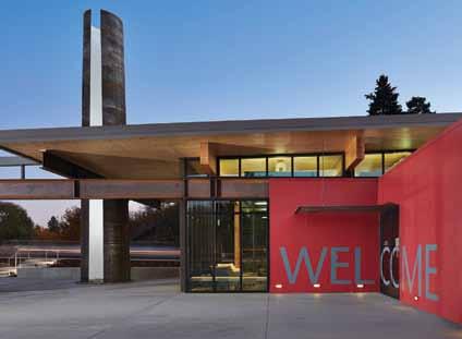
The Brelsford Visitor Center – Washington State University
Pullman, WA KPff Consulting Engineers
The 4,200 square foot Brelsford Visitors Center orients guests to WSU and serves as a vital resource for other attractions in the region. Pivoting display walls build public awareness, and support of the University’s lifechanging teaching, research, and outreach activities. The glazed pavilion is topped by an overhanging CLT roof that is supported by the 15-foot concrete “U” on one end and a 40-foot-tall steel plate tower on the other.
AWArd WiNNEr – CAtEgorY 1
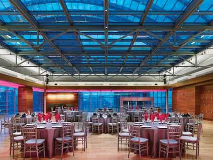
The Dorrance K. Hamilton Rooftop Garden at the Kimmel Center for the Performing Arts
Philadelphia, PA the Harman group, inc. The enclosure of the Dorrance K. Hamilton Rooftop Garden at The Kimmel Center is a structural glass gem within the barrel vault of Philadelphia’s premier Performing Arts Center. Structural elegance and simplicity were key to developing a workable supporting structure for the glass box, enclosing the space while maintaining the high level of vibration and acoustic separation necessary to the Perelman Performing Arts Center below.
AWArd WiNNEr – CAtEgorY 2
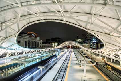
Denver Union Station Train Hall
denver, Co Skidmore, owings & Merrill llP
SOM Structural Engineers, working closely with SOM Architects, designed several steel and fabric pavilions for Denver Union Station Intermodal Hub. The focal point for the new station – the Train Hall structure – was conceived as an efficient and formally expressive means of clear-spanning 180 feet across multiple railway tracks. The primary structural system consists of eleven steel “arch trusses” spanning nearly 180 feet from a single large-diameter pin connection. The arch-trusses and cantilevered trusses support a tensioned PTFE fabric.
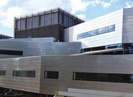
“Trefolo” University Building forlì, italy Proges Engineering S.r.1
The so-called “Trefolo” is the set of paths that connect the lecture halls at the University Campus in Forlì, Italy. It consists of three twisting tubes with variations in height and plan. The three tubes (with a total length of about 100 meters or 328 feet) rest on irregularly spaced vertical elements (props and stairwell partition walls) with several significant spans. Structural challenges included aspects in relation to the structure’s behavior under static and seismic conditions. In addition, difficult site conditions presented numerous challenges during construction.
AWArd WiNNEr – CAtEgorY 2
University of Louisville Student Recreation Center
louisville, KY rangaswamy & Associates, inc. With a growing urban campus, the University of Louisville student body saw an increasing need for additional intramural and recreation space. The steel framed $27 million Student Recreation Center encompasses 128,000 square feet and contains six new gymnasiums, a multi purpose court, an indoor cantilevered jogging track, and more. Due to space constraints on campus, the building has an irregular geometry which includes stacked gymnasiums and multiple cantilevers. Several innovative structural systems were required to meet the multiple framing complexities on this building.

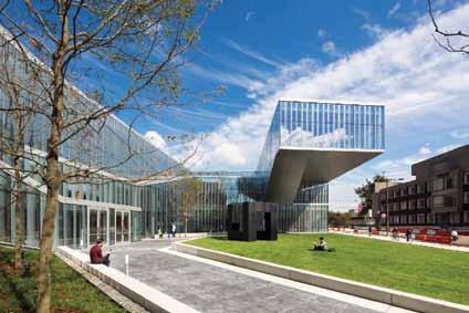
AWArd WiNNEr – CAtEgorY 3
Krishna P. Singh Center for Nanotechnology – University of Pennsylvania
Philadelphia, PA Severud Associates Consulting Engineers, PC The intra-disciplinary Singh Center for Nanotechnology ascends as a spiral to The Forum, which is a 68-foot cantilevered room. By design, it accommodates collaboration and sensitive nanotechnology research including clean rooms and a transmission electron microscope. The cantilevered Forum is designed to accommodate lectures and social events, with vibration considerations such as dancing. The stepping southern façade encloses the sunny galleria atrium with a curtain wall cut in two directions by a sloping roof.
MAST Foundation
Bologna, italy Proges Engineering S.r.1
MAST Foundation is a cultural and philanthropic institution that focuses on art, technology and innovation. Steel structures are used for the main building functions; secondary functions are underground construction in reinforced concrete. Steel structures forming the building are the synthesis of the research for specific solutions to complex problems. The result is that it is not possible to recognize the presence of structures in part of the building while, in another part of the building, structures emerge in all of their strength and elegance of expression.
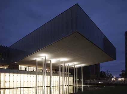
Courtesy of Christian Richters.
AWArd WiNNEr – CAtEgorY 4
Music City Center
Nashville, tN ross Bryan Associates, inc.
Nashville is known as Music City USA, and when a new convention center was proposed, it was aptly named the Music City Center. Located in the rolling hills of Middle Tennessee, the architects incorporated both Music City and rolling hills themes into the design of the building. The grand ballroom is shaped like a guitar. The 14-acre roof is curved in two directions and includes a 4-acre vegetated green roof to mimic rolling hills. These features resulted in a stunning building and presented significant design challenges for Ross Bryan Associates, Inc.

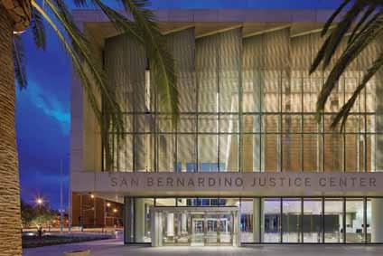
AWArd WiNNEr – CAtEgorY 4
San Bernardino Justice Center
San Bernardino, CA Skidmore, owings & Merrill llP
The San Bernardino Justice Center (SBJC) is the largest project constructed for the Administrative Office of the Courts, and the first to embrace life-cycle analysis considering the structural performance and return on investment in a region of high seismicity. With extraordinarily high site-specific ground motions, SBJC utilizes base isolation bearings and dampers to manage large ground motions. SBJC features a steel superstructure with special moment frames and supplementary viscous damping devices. The triple-concave friction pendulum seismic isolation system, located on the mat foundation, accommodates 42 inches of lateral movement.
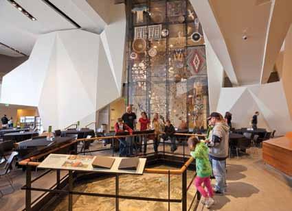
Utah Museum of Natural History Salt lake City, ut dunn Associates, inc.
Nestled in the foothills above Salt Lake City, the 163,000 square foot Natural History Museum of Utah houses a collection of 1.2 million artifacts. The building is composed primarily of exposed concrete with copper-alloy cladding. Between the copper, the lighter concrete and the metal panels, the building blends into the mountainside by using colors that complement its natural surroundings. Intended to teach and inspire visitors about the natural world and our place within it, the museum creates a distinct architectural and cultural significance for the state of Utah.
AWArd WiNNEr – CAtEgorY 5
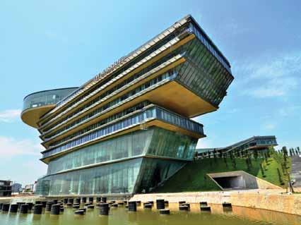
JW Marriott Hanoi Hotel
Hanoi, Vietnam leslie E. robertson Associates
The Marriott International Hotel, Hanoi also serves as the home of Vietnam’s National Convention Center. This project consists of a nine story, five-star, 500 room Marriott hotel and attached parking garage. The estimated size of this waterfront project is 800,000 square feet. The complex building uses steel trusses combined with reinforced concrete. The building’s design takes its inspiration from the dragon, which evokes the rich heritage of Vietnam.

AWArd WiNNEr – CAtEgorY 6
San Francisco-Oakland Bay Bridge New East Span
oakland, CA t.Y. lin international/Moffatt & Nichol, Joint Venture Located between faults capable of producing destructive earthquakes, the San Francisco-Oakland Bay Bridge New East Span is a regional lifeline structure with a 150-year design life, and is designed to open to emergency traffic within days after a major seismic event. It features engineering innovations and advancements such as shear link beams in the single tower, hinge pipe beams and specially-designed expansion joints in the bridge decks, and foundations that reach up to 300 feet below the water’s surface to anchor in stable soils.
Courtesy of Henrik Kam 2013.
140 New Montgomery
San francisco, CA Holmes Culley

With the latest analysis technology and an innovative strengthening scheme, Holmes Culley designed a seismic retrofit to preserve San Francisco’s first skyscraper. Using Performance Based Engineering, a full non-linear analysis model was developed to analyze the existing building. The new structural solution utilizes outrigger trusses distributed at two locations over the height of the building, supported by super-columns at the exterior, to maximize effectiveness of the core walls; and it satisfies the Secretary of the Interior’s standards for the treatment of historic properties.
AWArd WiNNEr – CAtEgorY 7
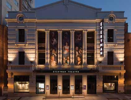
Everyman Theatre
Baltimore, Md Keast & Hood Co.
The project to renovate historic Everyman Theatre in Baltimore, Maryland, revitalized an abandoned property for new use by a community theater organization. Encompassing historic preservation, creative design, construction craftsmanship, and good stewardship, the project did more than create a modern performing arts venue – it contributed to positive neighborhood and economic renewal in Baltimore’s West Side arts district. Structural design challenges included accommodating acoustics for two stacked theaters, isolating the structure from an adjacent train tunnel, developing a unique and cost-effective system to restore the deteriorated façade, and reacting to structural surprises and not one, but two, natural disasters.
AWArd WiNNEr – CAtEgorY 8
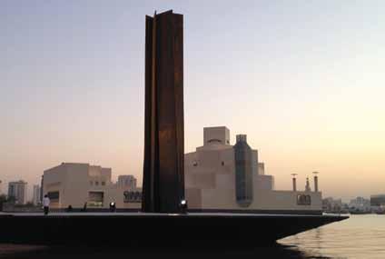
Richard Serra’s “7” Sculpture
doha, Qatar leslie E. robertson Associates
Located on a man-made peninsula in Doha, Qatar, Richard Serra’s sculpture “7” is composed of seven 4-inch thick, 80-foot high by 8-foot wide rectangular steel plates arranged as a heptagon in plan. Each plate leans and tilts towards the top of the sculpture. The material is intended to rust in a pattern conducive to the artist’s vision. Leslie E. Robertson Associates (LERA) determined the geometric layout of the sculpture in 3-dimensional software, reviewed the stability of the slender plates under thermal, wind, and seismic loads, and designed the connections between the individual plates and the sculpture’s supports.


