42 minute read
Building Blocks
updates and information on structural materials Structural Insulated Panels (SIPs) have historically been used more for residential construction than for non-residential construction. However, SIPs are gaining popularity in the commercial arena, especially for school construction. There are several schools throughout the country that have incorporated SIPs. One such school is Silvis Middle School in Silvis (East Moline), IL. This 52,600 square-foot facility was designed with SIP roof panels over metal bar joists, steel beams, and steel columns. SIPs were also used for the exterior walls, creating a full SIP building envelope. It is often assumed that SIP construction is more expensive than other construction methods. However, one of the reasons that SIPs were selected as the method of construction for the Silvis Middle School project was because they were the least expensive of the options that were being considered for the exterior walls.
Using Structural Insulated Panels on Non-Residential Structures A Case Study By Thomas A. Moore, P.E., LEED AP Thomas A. Moore, P.E., LEED AP is Project Manager at Steven Schaefer Associates, Inc., Consulting Structural Engineers in Cincinnati, OH. Thomas also serves on the Board of Directors and as the Educational Committee Chair for the Structural Insulated Panel Association (SIPA). He can be reached at tam@ssastructural.com. In addition, companies and individuals can be contacted through the member directory that is available on the SIPA website at www.sips.org.
The Role of the SIP Engineer Structural Insulated Panels are a pre-engineered building component, similar to pre-engineered wood trusses. SIP manufacturers produce SIP shop drawings, which are then reviewed by the project design team. On non-residential projects (and some residential projects), these shop drawings must be stamped by a PE licensed in the state where the project occurs. The SIP engineer reviews panel thicknesses, panel spans, connections, etc. The main difference between SIPs and wood trusses is that SIP span charts and load tables are typically based on testing, rather than material properties and calculations. Most SIP manufacturers have a code listing through ICC or an independent testing company. The manufacturer’s code listing will typically include an axial load table for wall panels and transverse load tables that would apply to wall, floor, and roof panels. There is also usually a shear wall capacity indicated, which is sometimes referred to as a “racking shear” capacity. The role of the SIP engineer is to compare the code-required design loads to the allowable loads in the code listing. Adjustments are then made, as required, to insure that the structure can resist the required design loads. Like any other pre-engineered system, there is a line between what is designed by the specialty engineer and what is designed by the engineer of record. This line can become blurred at times, especially on a project where the architect and/ or engineer of record are not familiar with structural insulated panels. It is important to identify the scope of work of the specialty engineer (SIP
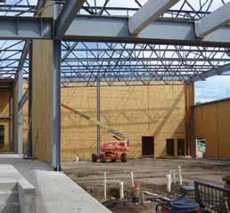
SIP wall panels go up first, followed by the roof panels, providing a strong, well-insulated building enclosure.
engineer) up front, in order to avoid overlap or gaps in the structural design on the project. Ideally, the SIP engineer would only be responsible for the component loads that apply directly to the SIP panels, and not to the global loads that apply to the building as a whole. However, some of these global loads (like shear wall loads) might be calculated by the engineer of record and given to the SIP engineer to check against the capacity of the SIPs.
A Diaphragm is a Diaphragm is a Diaphragm
One structural element that is present on most buildings is a diaphragm. SIP structures are no different. Every SIP roof will act as a roof diaphragm. The challenge is that most SIP manufacturers do not have specific allowable diaphragm values indicated in their code listing. The main reason for this is that they have not had specific ASTM diaphragm testing performed on their panels. The allowable “racking shear” values indicated in some manufacturers’ literature are often used when checking both shear walls and diaphragms. This is a valid approach, but it’s not quite as simple as just comparing the numbers. All shear walls and diaphragms have chord forces that must be accounted for in the design, and this applies to SIP structures too. Fortunately, most SIP shear walls have continuous wood studs embedded in the ends of the panels, and they serve as the chords at the ends of shear walls. Hold down anchors are attached to the bottom of those studs to resist overturning forces, where applicable. The top and bottom plates of each shear wall will also serve as chord elements, and those plates need to be able to resist the chord forces as well. Roof diaphragms are typically much larger than shear walls, which can be a blessing and a curse. The benefit is that diaphragm forces are resisted along the full length of the perimeter walls or

other lateral force resisting elements. The challenge is that the wood 2x members that are embedded in the edges of the roof panels will not be continuous, making it necessary to check/design the joints for the chord forces. In addition, attachment of the diaphragm to the structure below must be designed just like any other diaphragm. On the Silvis Middle School
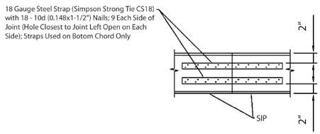
Figure 3. Figure 1.
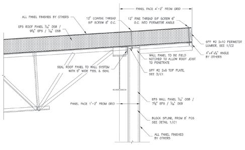
project, the SIP manufacturer was required to have diaphragm testing performed on their panels in order to satisfy the project design team. As a result, diaphragm test reports were available, which included specific edge conditions that were used during the testing process. See Figures 1 and 2 for details of the edge conditions that applied to the perimeter
Figure 2.
of the roof diaphragms on that project. These sections were taken from the diaphragm test reports, and they were included as part of the SIP shop drawings for the project. Section 3-3 shows metal straps being used to transfer tension chord forces across a joint in the 2x members embedded in the perimeter of the roof panels. If the roof diaphragm had consisted of metal roof deck over steel framing, the roof diaphragm forces would have been compared to allowable diaphragm capacities published in the metal deck manufacturer’s literature. Those allowable diaphragm capacities would fluctuate, depending on the spacing between fasteners at the edges of the deck. Metal deck diaphragms have a higher capacity when they are attached to the structure more frequently, and when they have more fasteners at the joints between sheets. SIP roof diaphragms are no different. The diaphragm testing was performed on SIP roof panels with edge and joint fasteners spaced at 6, 4, and 2 inches on-center. The results indicated that SIP diaphragms have higher capacities when the fasteners are spaced closer together. Therefore, the general concept of designing a SIP diaphragm is really no different than designing diaphragms of other materials. The Structural Insulated Panel Association (SIPA) has purchased the
220
Structural Design Spreadsheets
www.Engineering-International.com
Accurate
Just input in green highlighted cells; the spreadsheet and VBA program do the calculations.
Each spreadsheet includes drawings and code references; Copy/Paste results to AutoCAD; Quick-Link, see “What Is New?” at top of website homepage.
Technical Support, Software Updates (emailed).
Helpful
Prompt
diaphragm test results from the SIP manufacturer for the Silvis Middle School project, and those results will be made available to other SIP manufacturers that are SIPA members. This will go a long way toward allowing the use of SIPs on other non-residential projects, particularly by SIP manufacturers that have previously never had diaphragm test reports that they could use.
Do the Details Match the Design Intent?
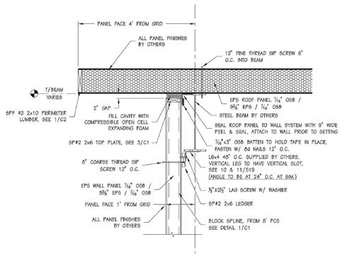
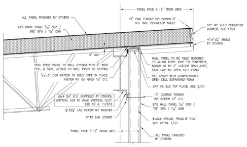
On the Silvis Middle School project, the SIP roof panels were supported by steel bar joists and steel beams. The lateral force resisting system for the building consisted of a combination of steel braced frames and steel moment frames. Design engineers asked if the SIP wall panels were intended to take axial load from the roof panels, and were told that they were not. They also asked if the wall panels were intended to act as shear walls, and were told that they were not. The wall panels were intended to resist transverse wind loads only, and they were not to be designed for any other loads. On the project drawings, the SIP roof panels were shown being attached directly to the top of the SIP walls, which were located immediately adjacent to the perimeter line of framing. Since the bottom of the roof panels were shown in direct contact with the top of the wall panels, the steel framing could not deflect without imposing axial load into the wall panels. In addition, the direct attachment of the roof panels to the wall panels would not allow the steel moment frames to “drift” without imposing shear load into the wall panels. Since the details were not consistent with the design intent, the design engineers suggested changes to the detailing. In order for the steel roof framing to deflect without applying load to the top of the wall panels, a 2-inch gap was created between the top of the wall panels and the bottom of the roof panels. This gap was then filled with compressible foam to complete the building envelope (Figures 3 and 4, page 15 ). Allowing the steel moment frames to drift without applying shear loads to the wall panels was a much more challenging task. The tricky part was that the wall panels still had to resist transverse wind loads, but they could not be directly attached to the roof panels. The solution was to provide a slotted connection that would allow movement in the direction parallel to the wall, but that would resist movement in the direction perpendicular to the wall. Since the perimeter
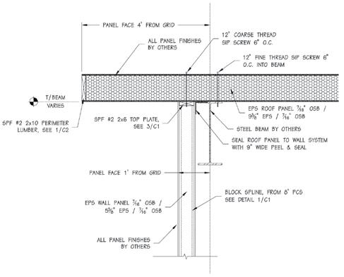
Figure 5.
Figure 6.
line of steel framing was adjacent to the wall panels, this connection had to be made at the bottom of the steel beams, for accessibility reasons. The connection could not be made at the top of the beams, because there was no access to the fastener once the walls were in place (Figures 5 and 6 ).
Conclusions
Structural Insulated Panels (SIPs) can be used on non-residential structures, as well as residential structures. Many of the design challenges that designers face when designing with SIPs are no different than when designing with other materials. The general concepts of structural design still apply when designing with SIPs – complete load paths, applied loads must not exceed allowable loads, detailing must be consistent with design intent, etc. SIP manufacturers and SIP engineers typically have a lot of experience and knowledge with regards to designing and building with SIPs. Design teams should not be afraid to tap into that knowledge and experience.▪
This article was previously published in the Wood Design Focus, Spring 2012. It is reprinted with permission.
Rehabilitation of Historic Holmes Street Bridge
By Robert E. Mateega, P.E.
Historic Holmes Street Bridge.
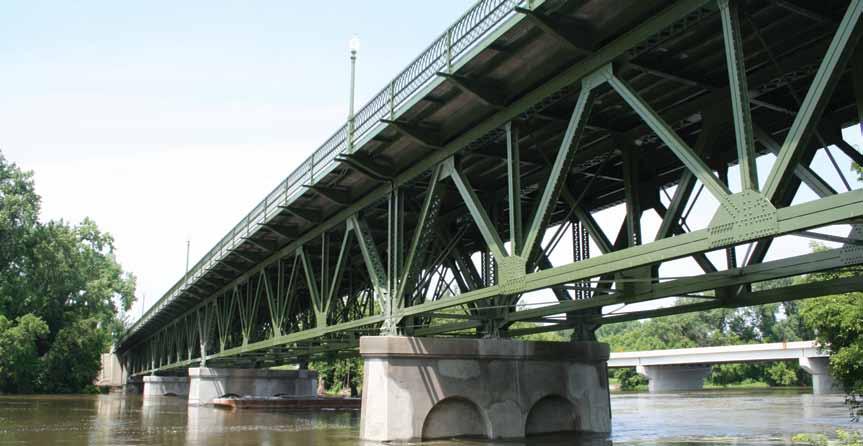
Bridges across the country are deteriorating or becoming functionally obsolete. Therefore, Departments of Transportation (DOTs) across the country have to identify and save historic bridges, thereby streamlining the replacement of non-historic bridges. The Minnesota Department of Transportation (MnDOT) identified the Holmes Street Bridge (Bridge No. 4175), commonly referred to as the Shakopee Truss Bridge, as one of 24 bridges in Minnesota to preserve once funding became available. For the Holmes Street Bridge, funding became available with passage of the American Recovery and Reinvestment Act (ARRA) of 2009. The project team of HDR as the Bridge Engineer and Mead & Hunt as the Project Historian faced many challenges. The first was the need to complete not only the inspection, analysis and rehabilitation report in six months, but also receive approval on final rehabilitation plans and specifications from MnDOT, the State Historic Preservation Office (SHPO) and the Federal Highway Administration (FHWA). A similar project would normally take 12 to 18 months. The next challenge was to identify engineering solutions that would meet safety and maintenance requirements, while preserving the historic features of the bridge. The inspection and analysis revealed the bridge to be in generally poor condition, with severe to critical deterioration in various steel and concrete members. Innovative design solutions that preserved the historical significance of the bridge included replacement of the existing ornamental railing in-kind with a safety modification, installation of replica lighting, replacement of some truss members and steel overhang brackets with shop fabricated members using rivets, and rehabilitation of concrete components using unique renovation techniques.
Bridge Description
The Holmes Street Bridge, built as a highway bridge in 1927, provided access across the Minnesota River for the city of Shakopee and points west to the Twin Cities Metro Area. Listed in the National Register of Historic Places (National Register) as a rare example of a deck-truss bridge in Minnesota, the Holmes Street Bridge is a 645-foot long bridge with an out-to-out width of 42.4 feet. The superstructure consists of two 30-foot long cast-in-place reinforced concrete deck girder south approach spans, four 125-foot long riveted steel deck truss main spans, and two 30-foot long cast-in-place reinforced concrete deck girder north approach spans. The truss spans consist of three parallel riveted steel Warren trusses with verticals. The bridge deck consists of a 30-foot wide roadway and two 6-foot wide raised cantilever sidewalks. The substructure consists of a U-shaped reinforced concrete South Abutment, two reinforced concrete south approach piers with four arched openings, three reinforced concrete river piers with two recessed arches on each side, two reinforced concrete north approach piers with four arched openings, and a U-shaped reinforced concrete North Abutment that features a stairway on the east side. In order for a property to be historic, it has to have characterdefining features which are prominent or distinctive aspects, qualities, or characteristics that contribute significantly to its physical character. Features may include materials, engineering design, and structural and decorative details. The Shakopee Truss Bridge has two character-defining features which were defined as follows in the MnDOT Historic Bridge Management Plan for Bridge No. 4175 (June 2006): • Feature 1, Deck-truss design and construction. The Shakopee
Truss Bridge is a rare example of a deck truss bridge in
Minnesota. This feature includes the four main spans, each of which has three riveted, steel trusses designed in a Warrenwith-verticals configuration. • Feature 2, Classical Revival architectural details. Because of its urban location as a gateway to downtown Shakopee, the
Shakopee Truss Bridge was designed with Classical Revival stylistic elements. This feature includes recessed panels in the concrete river piers (Piers 3-5), open-arched concrete piers in the approach spans (Piers 1-2 and 6-7), recessed panels on the abutments, ornamental metal railings on the approach spans and main spans, concrete parapet railings on the abutments, and stairways adjacent to the north abutment.
Th e project team performed an in-depth inspection of the bridge from within arm’s length of each member. Access to inspect the bridge truss members was provided from an Under Bridge Inspection Vehicle (UBIV) with a 60-foot reach. Th e in-depth inspection revealed delaminating and spalling concrete members; severely corroded ornamental railing members; severely corroded sections of stringers, fl oor beams and overhang brackets; severely corroded truss members; gusset plate section loss; pack rust; and frozen bearings. Most of the deterioration of the steel members was located in areas that were exposed to moisture, namely the exterior trusses on either side of the bridge and areas adjacent to the open joint at the end of each truss span. LARSA and STAAD 2D truss models were created to determine the forces in the various truss members. Prior to the project, it was determined that, following rehabilitation, the bridge would be reopened as a pedestrian and bicycle bridge with vehicles using a new bridge constructed downstream. Th erefore, the bridge deck was analyzed using the controlling load case between an 85 psf pedestrian live load or an American Association of State Highway and Transportation Offi cials (AASHTO) standard H-10 Design Truck which consists of 4 kip front axles and 16 kip rear axles separated by 14 feet. Th e raised sidewalk was analyzed using only the 85 psf pedestrian live load. A special load case consisting of the UBIV was also considered, as this would be the vehicle used to inspect the bridge. Th e analysis followed the AASHTO Manual for Bridge Evaluation and the MnDOT LRFD Bridge Design Manual. Th e analysis models coupled with spreadsheets developed by the project team to analyze gusset plates, and information from the
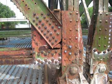
Deteriorated truss members and gusset plates prior to repair.
in-depth inspection, revealed which portions of the bridge needed to be repaired or replaced. Th is included gusset plates, fl oor beams, stringers, overhang brackets, and truss members; the raised concrete sidewalks; the roadway deck; expansion joints; bearing pins; the ornamental metal railing; and concrete surfaces.
Repair Recommendations and Innovative Solutions
As the bridge was historic, the project team had to ensure that the rehabilitation plans on this eight-span concrete girder and steel deck
ADVERTISEMENT–For Advertiser Information, visit www.STRUCTUREmag.org


Structural Software Designed for Your Success

Easy to Learn and Use Analyze “Just about Anything!” Design: Steel, Wood, Concrete, Aluminum, and Cold-Formed
www.iesweb.com
Free 30-Day Trial

IES, Inc. | 519 E Babcock St. Bozeman MT 59715 800-707-0816 | info@iesweb.com

truss structure complied with Section 106 of the National Historic Preservation Act, and followed guidelines in the National Park Service Preservation Brief 15, Preservation of Historic Concrete. Additionally, the project could have no adverse effects on the historic resource as determined by MnDOT, SHPO and FHWA. To streamline the process of determining the appropriate treatment methods for the extensive concrete repairs, the project team developed a repair matrix that distinguished treatments based on location and public visibility. For example, the team determined that concrete areas not visible, such as river pier areas, could be repaired with standard MnDOT construction techniques. Areas clearly visible to the public, including abutments and parapets, required historic repair techniques to ensure conformance with historic surfaces, and were included in the detailed project specific specifications. The specifications included requirements that the repaired concrete match the adjacent existing concrete in terms of finish, texture, surface detail and color. The contractor was required to provide a minimum of 3 samples, at least 12 inches by 12 inches in size, to demonstrate that they could match the adjacent existing concrete. The matrix clarified and expedited the appropriate treatments for both plan development and communication with the contractor. An additional repair matrix was developed to address the repair and/ or replacement of deteriorated steel truss members. Rivets are a key feature of historic truss members, but few contractors today are able to install rivets in the field. When 30 steel sidewalk overhang brackets and six bottom chord members in highly visible areas were severely deteriorated and required replacement, the project team specified that the new members be shop-fabricated with rivets. Historic railing typically presents design challenges due to noncompliance with current safety standards. The original metal ornamental railing was no exception. Not only did the railing openings not meet current MnDOT or AASHTO standards, but multiple sections exhibited critical deterioration. The project team looked at six different options ranging from reuse to replication to redesign, but based on issues of deterioration, cost and safety, the team chose to replicate the original railings with minor modifications, while refurbishing original castiron newel posts. AASHTO standards require that openings between members of pedestrian railing shall not allow a 6-inch sphere to pass through the lower 27 inches of the railing and an 8-inch sphere should not pass through openings above 27 inches. MnDOT standards, which are more stringent than AASHTO, require that openings between members shall not allow a 4-inch sphere to pass through the lower 27 inches, and a 6-inch sphere should not pass through any opening above 27 inches. The original railing allowed a 6-inch sphere to pass through openings both below and above 27 inches. Therefore, MnDOT issued a design exception for the project, whereby the MnDOT requirements for the openings in a pedestrian railing were waived in favor of the AASHTO requirements. The replica railing was able to meet AASHTO opening requirements by the addition of a 3/16-inch steel stainless steel cable, which prevented a 6-inch sphere from passing through the lower 27 inches of the railing. It was determined that the addition of the stainless steel cable was less intrusive on the character-defining feature, than changing the dimensions of the railing to meet today’s design standards. To reduce cost, the team recommended button-head bolts with acorn-style nuts replicate the 1,200-plus rivet connections of the original railing. Another innovation related to historic truss members was a solution to prevent future deterioration, most of which was due to drainage runoff from the deck drains and open joints at each truss end. Hydraulic analysis showed that the deck drains could be eliminated, and the open joints could be replaced with strip seal expansion joints.

Shop-fabricated bottom chord truss member with rivets.
This was a simple and ingenious solution to damaging deck drainage runoff and the subsequent corrosion of steel truss members.
Construction and Lessons Learned
Construction of the rehabilitation project was performed by Edward Kraemer and Sons as the prime contractor. For concrete repairs, the contractor used shotcrete with subsequent surface treatment, employing color stain and microabrasive blasting for surface texture and graffiti removal on highly visible historic areas. This was the first time the technique was used by MnDOT for this purpose or permitted by the SHPO for historic concrete repair. The contractor also successfully prepared test panels for on-site product demonstrations for MnDOT and SHPO, and now these methods are approved and provide practical solutions to historic concrete repair challenges for future projects. One of the lessons learned on the project was to pay close attention to member removal and the location of rivets with heads on only one side. Removal of bottom chord members was very challenging since the gusset plates at the bearing points were remaining in-place; some of the rivets in the gusset plate at the bearing point only had a head on one side and therefore could not be replaced. The contractor was able to remove the bottom chord member by removing rivets with heads on both sides, and prying the member out. The project benefited from having repairs priced per type, e.g. stringer repair or truss member repair. Given the old age of the bridge, additional areas requiring repair were identified when portions of the bridge were removed. Since repairs had been priced by type, which included means and methods, the compensation of additional repair items was straight forward, without having to determine the additional cost of installing and carrying out the repair.
Conclusion
Rehabilitation of the historic Holmes Street Bridge preserved an elegant 84-year old structure for future generations of pedestrians and bicyclists. Innovative, collaborative engineering design preserved or restored historic materials and features, including ornamental railing, riveted bridge components and concrete detailing. The Holmes Street Bridge rehabilitation, stands as a creative model for similar projects in communities throughout Minnesota and the United States.▪
Robert E. Mateega, P.E. (robert.mateega@hdrinc.com), is a Senior Bridge Engineer at HDR Engineering Inc., in Minneapolis, Minnesota.
Translucent Dome for Argentine Soccer Stadium
Matthys Levy, P.E.
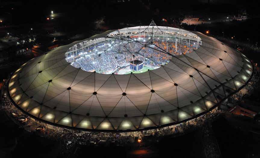
Figure 1: Aerial view of completed stadium showing figure-eight-shaped opening.
The design of the roof of the recently completed La Plata football stadium represents a serendipitous merging of two concepts: the award winning competition entry by the architect, Roberto Ferreira, and the Tenstar Dome™ structure originally developed by Weidlinger Associates for the Georgia Dome. Compared to the Georgia Dome, however, the La Plata project presented some unique engineering challenges. Instead of having a continuous oval perimeter, the plan of La Plata is based on two circles 279 feet (85 meters) in diameter whose centers are separated by 157 feet (48 meters), resulting in a configuration that looks like a MasterCard® symbol (Figure 1). Furthermore, the requirement for natural ventilation resulted in the need for openings at the two peaks, 222 feet (67.6 meters) above the playing field, defined by the center of the two circles and protected from rain by umbrellas, affectionately called “sombreros.” Finally, a compression ring around the arena, instead of being built of concrete as at the Georgia Dome, was conceived of and built as a triangular steel truss, partly to introduce lightness in what is a very massive structure, to encourage free airflow in this naturally ventilated dome, and to provide space for two levels of skyboxes and control booths. The 53,000-seat soccer stadium in La Plata, Argentina, opened in 2003, lacking its signature twin-peaked fabric dome, and reopened to great fanfare on February 17, 2011, after completion of its roof structure, which was two thirds covered. Construction of the first phase of the project started in 1998, resulting in the completion of the playing field somewhat below original grade and an earth berm on which was poured a concrete seating bowl, crowned by the trussed steel compression ring. The material for the roof, including the fabric and cables for the Tenstar Dome, was also purchased at that time and placed in storage when Argentina faced a financial crisis in 2000. For the next 11 years, the stadium, with its trussed compression ring in place, stood waiting for construction of the roof. The trussed compression ring (Figure 2) consists of steel pipes with diameters of 42 inches (1,066 millimeters) for the top chord, 36 inches (914 millimeters) for the posts, and 28 inches (711 millimeters) and 18 inches (457 millimeters) for the diagonals. The vertical posts of this truss form a colonnaded gallery at the back of the stands and sit on baseplates anchored to the foundation which consists of concrete pile caps at the top of the berm, with concrete piles that extend down to virgin soil. Concrete grade beams tie the pile caps together and act essentially as the bottom chord of the trussed compression ring. Since the compression ring must carry both gravity loads from the roof and wind loads acting against the roof surfaces, lateral resistance is required between the ring and the foundations. The roof structure is also subject to thermal stresses due to temperature variations resulting from restraining the ring at the foundation. These were analyzed and were found to be acceptable if one post on each side of the kink (where the two circles meet) was radially released. This was accomplished with guided Teflon® bearings that permit radial displacement but not circumferential movement. Framing for the skyboxes and control
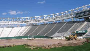
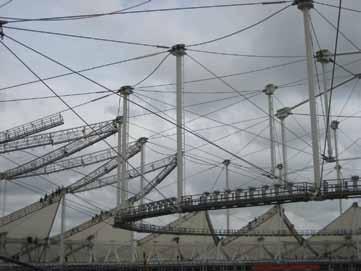
Figure 3: Interior view during construction, showing catwalk on bottom hoop cable and ridge cables at top nodes. Figure 4: Attachment of cables to post.
booths was set into and hung from the 42.6-foot (13 meters) high and 29.5-foot (9 meters) wide trussed compression ring. The vertical posts were shop fabricated with gusset plates to catch diagonal and radial tubes. At the top of each post, a gusset plate was provided to engage the socket of the cable dome’s radial cables and fitted with holes through which temporary construction cables could be connected. Since the circumferential top chord pipe is always in compression, flanged, bolted connections were installed at the top of the posts. The truss diagonals are either bolted or pinned to the joint weldments. The top of the posts form the spring line for the dome, which consists of the triangulated ridgenet of cables characteristic of a Tenstar Dome. A series of three tension hoops step inward and upward from this inner top chord of the truss. Cables sloping down from the top of the posts hold the first of these hoops. From the node formed by the intersection of these sloping cables and the first tension hoop, a rigid vertical post, called a “flying post,” rises to the first line of ridgenet nodes. From those nodes, diagonal cables slope down to the second tension ring, which supports a second series of posts. This sequence is repeated until reaching the top of the third ring, at which point another series of cables converges at the center of each peak. Catwalks are attached to each hoop cable, and bridges interconnect the catwalks for access to the lighting and sound systems and rigging for special events (Figure 3). Because of the kink at the center of the stadium that results from the reentrant perimeter, the members along the centerline are subject to compression rather than tension and are therefore pipes rather than cables. This introduced a complication in the erection of the dome and the need for added temporary towers. It also necessitated a field modification to the nodes at the top of the posts in the region of the kink to permit both radial and transverse rotation. The nodes at the top and bottom of each of the flying posts are unique weldments that have to accommodate the continuous tension hoop cables and diagonal cables, as well as attach to the post itself (Figure 4 ). The hoop cables that continue through the node sit in a slot formed by steel bars welded to a steel plate. They are clamped down with a second plate that is bolted to the first, creating a friction clamp. Since as many as four 3.9-inch (98-millimeter) cables are used in the first hoop, the resulting welded steel node assemblies are very large, with overall dimensions of 6.6 feet (2 meters) x 6.6 feet (2 meters) x 3.3 feet (1 meter) and weighing as much as 2 tons. The top weldment, with gusset plates for ridge cables and diagonal cables, is rigidly attached to the post, while the bottom weldment is pinned, permitting radial rotation. The Tenstar Dome is a tensegrity system that is defined as a “spatial network in a state of self stress.” The system acts like a truss in which the bottom chord is interrupted and follows the line of hoop cables around to the opposite side of the arena. The system is truly three-dimensional rather than planar, and therefore benefits from the triangularization of the structural elements. This improves loadcarrying capability and permits the unconventional geometry of structures such as La Plata. To prevent cables from becoming slack under load, the system has to be prestressed, resulting in an extremely rigid structure. Instead of providing a means of adjusting the tension in each cable, in a Tenstar Dome such as La Plata, lengths are fixed based on the final configuration of the dome and the level of prestressing needed. This implies that the system remains slack until the last cable or post is installed, and therefore impacts the erection system. Two temporary towers were built to erect the roof structure, one at the center of each of the two peaks (Figure 5 ). Jacking cables from these towers were run through sheave blocks (pulley devices) at each node of the assembled hoops, laid out on the ground, and run through another set of sheave blocks at the top of the ring, which were in turn connected back down to the hoops. This arrangement lifted the hoop simultaneously upward and outward into its final position, where
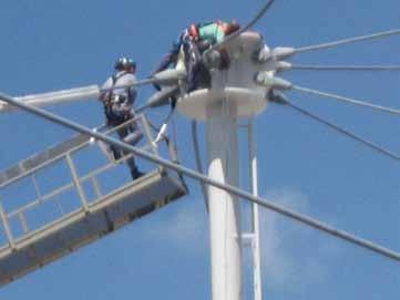
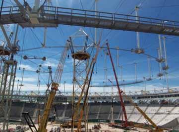
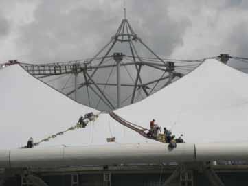
Figure 6: Installation of fabric cover over cable network.
it could be connected to the diagonal cables. To create the kink, a temporary cable was stretched across the stadium, connecting the two sides of the hoop cable. The vertical posts were then lifted into place and attached to the nodes in the hoop cable. Afterwards, the ridge cables were attached to the top of the posts. This same procedure was followed to the center of each peak. During the erection of the rigid members comprising the elements across the kink at the centerline of the stadium, secondary temporary towers supported the arch structure. Also, since the compression ring tends to move inward when the cable net is installed prior to the completion of the arch structure, a telescoping vertical member was provided at the center of the arch and was jacked once the structure was completely assembled, in order to move the ring back out to its final location. Once the cable network was complete, the fabric covering was installed (Figure 6 ). The special fabric used on this project is a hightranslucency Teflon-coated fiberglass that was developed to provide sufficient natural light for growing the turf. Although studies demonstrated the fabric’s effectiveness, the owners were concerned about the damage to the turf that would occur when the arena is used for special event such as concerts. Therefore, it was decided to pave the playing area and to use palletized grass panels that could be stored outside the stadium when not needed for soccer games. This solution helped make La Plata Stadium a truly multipurpose arena. This phase of the roof construction extended the fabric only to the second hoop, leaving a figure-eight hole in the center of the stadium. (Figure 7 ). However, the Tenstar cable dome structure is currently complete, and when the balance of the fabric and its two sombreros are added, the architect’s original conception will finally be realized. The construction of the La Plata dome recognizes the adaptability of the Tenstar concept to complicated shapes that can be built in stages to meet owners’ financing constraints. Variants of this concept are currently on the drawing boards, including a retractable roof that rides on top of the cable dome, providing a lightweight, aesthetically pleasing yet economical solution for covered arenas.▪
Matthys Levy, P.E. is chairman emeritus of Weidlinger Associates, Inc., and former director of its Building Design Group. Levy is the recipient of numerous professional awards. He is also the author of many popular books on structures and climate effects, including the classic Why Buildings Fall Down.
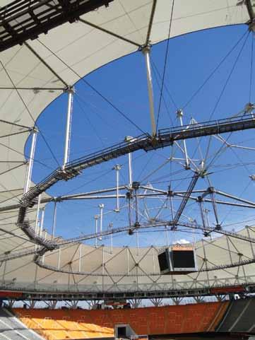
Figure 7: Interior view of completed roof.
The Team
Engineer: Weidlinger Associates, Inc., New York, NY Architect: Roberto Ferreira, Arquitectos, Barcelona, Spain Roof Contractor: Birdair, Inc., Buffalo, NY Steel fabricator: Astillero Rio Santiago, Ensenada, Argentina Cable supplier: Wire Rope, Montreal, Canada Software: LARSA and MCM/BLD3D
Materials
Cables: 500 tons Steel compression ring: 3,000 tons Skyboxes: 1,000 tons Posts, Arch pipes, Central pentagons: 800 tons Weldments, catwalks: 600 tons UltraLUX fabric: 29,300 square meters (315,268 square feet) and 27 tons

Composite Cast Steel Nodes Suspend 11-Story Office Building above Two Heritage Structures
By Carlos de Oliveira, M.A.Sc., P.Eng, Michael Gray, Ph.D. and Jeffrey Stephenson, P.Eng
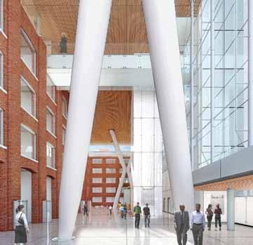
Although the Queen Richmond Centre West (Figure 1) in Toronto offers a brilliant example of adaptive re-use through its integration of two existing heritage buildings into the construction of a new 11-story office building, it’s the fact that the 11-story tower springs from above both existing buildings that makes Phase One of this development a truly unique structure. Critical to the realization of the design from both a structural and architectural perspective is the use of elegantly shaped 31,500pound cast steel nodes in the architecturally exposed structural steel framework supporting the building. In 2010, Allied Properties REIT commissioned Dermot Sweeny of Sweeny Sterling Finlayson &Co Architects (&Co) to design a landmark mixed-use development in Toronto’s entertainment district. &Co engaged Stephenson Engineering and, given the positioning of the two existing heritage structures on the site, presented the structural engineering firm with the challenge of suspending the office building above the two existing structures. This configuration would thus form a large L-shaped, glass-enclosed atrium with direct access from streets to the east and south of the complex as well as to a mid-block public lane to the north. &Co’s desire to offer tenants office space with clean, unobstructed ceilings led to their specification of a raised floor system for building services and ultimately drove their selection of an exposed reinforced concrete structural system for the 11-story tower – not the least-weight structure to suspend by any means. Stephenson Engineering’s early structural concepts for the support of the tower focused on the use of a mega-column and beam system which formed a moment frame assemblage capable of carrying the substantial gravity and lateral forces from the tower above. In addition to the considerable magnitude of the forces, also driving the size of these structural elements was the 70-foot clear height between street level and the underside of the tower. Although this structural scheme was capable of supporting the proposed tower, &Co challenged Stephenson to develop a more elegant concept. The Stephenson Engineering team held an internal design charette which, working with &Co, led to the development of the unique “delta frame” concept that was ultimately employed in the design and construction of the building. Essentially, each delta frame is an hourglass space frame configuration formed from two stacked rectangular-based space frame pyramids – the top pyramid being inverted such that the apex of both pyramids meet at a central point in space. With three such delta frames arranged within the complex’s L-shaped atrium and tied together with a diaphragm at their tops, the unbraced length of each of the inclined mega columns is reduced. Aligning each of the corners of the upper pyramids directly beneath tower columns above provides a direct load path for gravity loading. The three delta frames also form a major part of the lateral system – the only other effectual lateral support through the atrium space is provided by a single reinforced concrete stair and elevator core which descends down from the tower above. This concept immediately became the preferred solution by both the architect and the owner alike and became the focal point for all imagery surrounding the project (Figures 2 and 3).
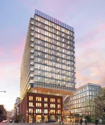
Figure 1: This rendering shows the site from the south-east corner of Peter Street and Richmond Street. Courtesy of Sweeny Sterling Finlayson &Co Architects Inc. and Allied Properties REIT.
Figure 2: Rendering of the atrium from the Peter Street entrance, directly beneath one of the delta frame structures. Courtesy of Sweeny Sterling Finlayson &Co Architects Inc. and Allied Properties REIT.
The next challenge was the design of the members comprising the delta frames. To achieve the strength and stiffness required to support the office tower, the round tubular steel members of the delta frame needed to be 1000 mm (393/8 inches) in outer diameter and, since steel tubes of that diameter are not readily available in wall thicknesses greater than 50 mm (2 inches), the steel legs had to also be concrete filled such that their composite strength and stiffness could be relied upon to carry the massive forces involved. The central kernel point of the three delta frames – the joint where the four legs of the lower pyramidal frame meet the four incoming legs from above – also presented a unique engineering and fabrication

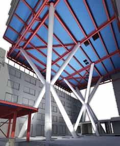
Figure 3: REVIT model view from outside of the Richmond Street entrance. Courtesy of Stephenson Engineering Ltd.
challenge. From an architectural perspective, concentric framing resulted in the least visually obtrusive support structure; however, the complex, overlapping field-welded central junction could not be reliably fabricated. Hence a nodal approach was required, where the central intersection junction would be fabricated separately with the incoming members to be connected to the node in the field. To accommodate weld fabrication of the node itself – to provide weld access, reduce joint overlaps, and to reduce the need for internal stiffening – the tubular members had to be spread apart from one another, which in turn introduced significant eccentricity in the framing and necessitated the use of an 8-inch thick central plate at the “waist” of the node to tie all of the tubular elements together. The eccentricity in the framing imparted additional bending demand on the already heavily loaded delta frame members. More concerning, however, was that the lateral stiffness of each of the delta frames was significantly reduced with this approach, as counteracting forces passing through the node had to be transmitted through the central plate in shear and bending rather than directly through to the diagonally opposite lower leg as would be the case with a very stiff or fully concentric node. ETABS analyses showed that the stiffness of the node significantly affected the distribution of lateral forces between each of the delta frames and the other elements of the lateral system. The architectural team raised concern as well, as the central node had ballooned to twice its originally intended size, with the splaying of the legs of the delta frame being somewhat unsightly and the horizontal band produced by the central plate being quite far from what was originally envisioned.
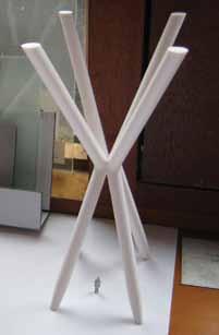
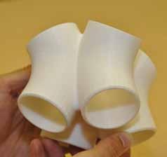
Figure 4: Rapid prototype of the cast steel node at 1:20 scale. Courtesy of Cast ConneX Corporation.
During this time, the construction manager and builder for the project, Eastern Construction, reached out to local steel fabricators to discuss the construction of the delta frame structures. The design team simultaneously contacted Cast ConneX, as Stephenson wanted to investigate whether the use of a cast steel node would better address the complex structural and architectural requirements for the delta frames. After some initial discussions, Cast ConneX was engaged by Eastern Construction to conduct a feasibility study, and carried out a preliminary volumetric optimization of the node and prepared a detailed costing for their design-build services. Satisfied that casting the nodes provided significant advantages and value over a conventionally fabricated node – improved strength, stiffness, and reliability and vastly improved aesthetics – Allied Properties engaged Cast ConneX via Eastern Construction to engineer, detail, and supply 3 identical cast steel nodes for the project. Simultaneously, local steel fabricator and erector Walters Inc. was engaged to provide design-assist services with respect to the rest of the structural steel framing on the project. Having already carried out a course volumetric optimization to identify the most economical overall dimensions for the node, Cast ConneX worked closely with &Co Architects on the node’s exterior shaping using 3-dimensional solid modelling software. When asked to contour nodes such as these, the automatic reaction is to maximize the size of transitional radii such that all surfaces are blended together. However, the supplier prepared two exterior geometry options: one where all transitional radii were maximized and an alternative where only the curvature in the vertical direction was maximized. Focused on
Figure 5: Rapid prototype of a full delta frame at 1:100 scale. Courtesy of Sweeny Sterling Finlayson &Co Architects Inc. and Allied Properties REIT.
the alternative geometry, delicately blending adjacent tubular extrusions together using variable radii, the resulting surface expression was of vertically continuous delta frame members. Rapid prototyping (Figures 4 and 5) was used to model two full delta frame assemblies – one featuring each node type – and the alternative nodal geometry was immediately identified as the preferred solution by the architectural team. Although shaping of the exterior of the node was primarily driven by aesthetics, shaping of the interior of the node was driven entirely by structural requirements and casting constraints. Since the legs of the delta frame were to be concrete filled, the supplier employed a cellular interior design which provides for the vertical continuity of the concrete fill within the legs of the delta frame members directly through the four independent chambers of the node. In so doing, concrete could be pumped from the bottom of each delta frame leg continuously
The easiest to use software for calculating wind, seismic, snow and other loadings for IBC, ASCE7, and all state codes based on these codes ($195.00). Tilt-up Concrete Wall Panels ($95.00). Floor Vibration for Steel Beams and Joists ($100.00). Concrete beams with torsion ($45.00).
Figures 6 & 7: Finite element analysis – equivalent stress results for a load case. Courtesy of Cast ConneX Corporation. Figure 8: One of the cast nodes after having just been removed from the heat treatment oven. Courtesy of Bradken Inc.
Figure 9: One of the nodes ready to ship to the machine shop. Courtesy of Bradken Inc.
through to the top of the 70-foot tall delta frame. This also provides for continuity of the steel-concrete composite action into the node itself. Cast ConneX provided Stephenson Engineering with guidance on their proper simulation of the node in their ETABS building model, ensuring that eccentricities, fixities, and stiffness assumptions at the node were appropriately modeled. Stephenson then used their updated ETABS model to pass loading information back to the supplier for their engineering design and analysis of the node itself, using 3-dimensional solid modelling and finite element analysis (FEA). Cast ConneX’s numerical model (Figures 6 and 7 ) consisted of both frame and solid elements, the latter being used to model the cast steel node and tubular hollow section stubs extending beyond the ends of the node’s nozzles. The frame members were tied to the distal ends of the finite element meshed tubular stubs in all degrees of freedom using a coupling constraint. Structural loading was applied to the top of the delta frame in the analysis model. Loading was provided by Stephenson Engineering as output from their ETABS model of the entire building structure. Factored forces were provided for the three unique delta frame support structures for 124 load combinations each. To eliminate the potential for input errors and to automate the exhaustive 372 cases to be analyzed, the loading was read from the electronic ETABS output files provided by Stephenson and written directly into the FEA software application by proprietary software developed by the fabricator. The analysis process was iterative, with several incremental changes being made to optimize the cast node’s internal shaping and with all analyses being re-run. The supplier prepared all casting specifications, prepared and sealed an engineering report on their node design, produced and sealed casting shop drawings, coordinated all casting manufacturing and machining, and delivered the finished castings to Walters. Cast ConneX selected Bradken’s Atchison, Kansas facility to cast the three 31,500-pound nodes (Figures 8 and 9). To address the lead time requirements for the production of the cast nodes, Eastern Construction authorized the casting manufacturing well in advance of releasing the remainder of the structural steel work scope. Walters’ design-assist services in relation to the cast node focused on the detailing of the welded joints between the casting’s nozzles and the incoming tubular steel jackets of the composite delta frame members, where they were able to significantly reduce the cost of field welding. Walters’ analysis showed that combined bearing and partial joint penetration welds would be sufficient to transfer the predominately compressive stresses at the joints, rather than employing complete joint penetration welds which would have required more than 4-times the weld volume. Additionally, Walters’ welding engineer reviewed Cast ConneX’s cast steel grade selection, and prepared and oversaw the qualification of the welding procedure specifications for the welds between the cast and rolled steels. This project provides a brilliant example of how best to leverage steel castings to enable the realization of an iconic building. The owner and design team’s open mindedness to consider alternative design and procurement methods was the key to the complete integration of the cast nodes into the design – meeting &Co Architects inspirational design intent, achieving a truly remarkable structural feat, and simultaneously improving constructability. Cast ConneX is often asked when casting a connection makes sense from a purely economic perspective. When the design team carried out their original feasibility and costing study for this project, a direct comparison was made between the costs to cast and to fabricate the nodes. This direct comparison of manufacturing costs alone showed the cast nodes to be somewhat more expensive. However, this supposed cost premium was likely covered several times over through the improvement of the structural effectiveness of the delta frames (particularly through their significantly improved ability to resist lateral loading which reduced structural demand on other elements of the lateral force resisting system), the simplification of the construction and concrete filling of the delta frame members, and – less quantifiably but perhaps most importantly from the Owner’s perspective – in the realization of a truly iconic design. A model of urban intensification and a shining example of sustainable construction with a target to attain LEED® Gold certification, this development will create an all new state-of-the-art office building commencing 70 feet above street level and offer a lobby and retail complex in the building’s soaring atrium that extends the public realm into a controlled environment. Construction of the building is ongoing, with tentative completion in 2014.▪ Carlos de Oliveira, M.A.Sc., P.Eng is president and principal structural engineer at Cast ConneX Corporation. Carlos is widely recognized as a foremost expert in the design and use of steel castings in building construction. Carlos may be reached at carlos@castconnex.com. An inventor of yielding connectors for high ductility non-buckling braced frames and a co-founder of the company, Michael Gray, Ph.D. is the vice-president of advanced technologies at Cast ConneX Corporation. Michael may be reached at m.gray@castconnex.com. Jeff Stephenson, P.Eng is Managing Principal at Stephenson Engineering in Toronto, ON. Jeff may be reached at jstephenson@stephenson-eng.com.
