32 minute read
Historic Structures
significant structures of the past
Union Bridge
First Bridge across the Hudson River, 1804
By Frank Griggs, Jr., Dist. M. ASCE, D. Eng., P.E., P.L.S.
Dr. Griggs specializes in the restoration of historic bridges, having restored many 19th Century cast and wrought iron bridges. He was formerly Director of Historic Bridge Programs for Clough, Harbour & Associates LLP in Albany, NY, and is now an independent Consulting Engineer. Dr. Griggs can be reached at fgriggs@nycap.rr.com.
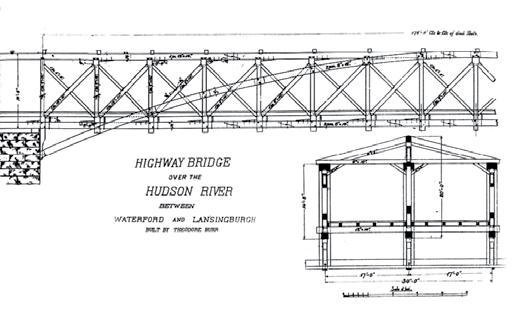
Cooper plan of Burr arch/truss. Cooper half truss – note: sidewalk framing not shown.
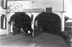
The Union Bridge, connecting Waterford and Lansingburgh, New York, was the first to cross the Hudson River in its 154 mile course from New York harbor northward. It was located near a long time ford and ferry crossing. The first act leading to the bridge was passed by the legislature on April 15, 1800 when it authorized building of toll bridges across the Hudson River. Nothing was done until late 1802 or early 1803, when a group of the leading men of Waterford and Lansingburgh proposed the formation of the Union Bridge Company to build a toll bridge at the site. At this time, they probably contacted Theodore Burr, a millwright from Oxford, New York, to advise them on a design. Burr was born in Torrington, Connecticut. After an apprenticeship to a millwright, he went to Oxford in the 1790s. The only other man who could have been contacted was Timothy Palmer, but he was busy building the Permanent Bridge in Philadelphia. (STRUCTURE® magazine, October 2013) Burr had earlier built a bridge across the Chenango River from his mill to the town of Oxford as well as many mills near his home. An act dated February 22, 1803 passed the Legislature that stated “John. D. Dickenson, Charles Selden…and their present and future associates, their successors and assigns, be and they are hereby created a body corporate and politic by the name of ‘The president and directors of the Union Bridge Company,’ for the purpose of building a bridge across Hudson’s River, at or near a ferry commonly called Hamilton & Scotts’s ferry leading from Waterford to Lansingburgh…” It covered the rules by which the corporation should be run and how elections were to be held, etc. It also said “it shall not be lawful for any person or persons to erect any bridge, across the said river within two miles up or down the said river, from the place where the bridge aforesaid shall be erected and built by the said company.” After 75 years, the bridge would become the property of the state. The only clauses dealing with construction of the bridge were in article VIII which stated that “the said bridge shall be built at least twenty-five feet wide, and be well covered with plank not less than three inches thick, the sides of the said bridge to be secured with good substantial railings, and shall be so constructed that at least one opening under the same, of not less than one hundred feet, between the piers, shall be left of the passages of rafts and boats.” It was on the Waterford Bridge that Burr developed the truss/arch pattern that he later patented in 1806 and again in 1817. His design was adopted for both roadways and railways over the next 50+ years. Unlike Timothy Palmer who built pure truss bridges, he relied greatly on arches to carry a portion of his load and had them built strongly into the stone abutments and piers. His truss was built integrally into his arch with details to ensure the two systems acted together. His bridge consisted of four spans of three trussed arches, yielding twin roadways 11 feet wide. He built a sidewalk along the northerly side of the bridge, outside of the northerly arch, by cantilevering it off the trusses with floor beams that ran continuously across the entire bridge. The best drawing of the arch/truss pattern was published in Theodore Cooper’s American Railroad Bridges article in the Transactions ASCE in 1889. Cooper won the Norman Medal for the article. He wrote that he had obtained the drawings from associates at RPI, where he graduated in 1857. He illustrated a half span on one of the two river spans. The key feature of the bridge, which originally was not covered, were the arches that started below the deck at the abutments and ran near the top of the top chord at mid span on the shore spans and above the top chord on the river spans. The deck was generally flat, or nearly flat, to accommodate traffic. It rested on cross beams that were set on the bottom chord of the truss.
Cooper’s dimensions of each member of this truss and his splice and connection details are shown in the illustration on page 22. He had cross bracing between the top chords to stabilize the trusses above the deck level. Originally the bridge had no roof, so the framing shown is for the 1814 rehabilitation. The height of the truss from bottom of the bottom chord to the top of the top chord was 14 feet 8 inches. His arches were twin 8 x 16-inch members with the verticals, lower chord and upper chord bracketed by the twin arch members. The top chord was a single 12 x 16-inch and his bottom chord was twin 8 x 14-inch. His single verticals were 9 x 12 inches and single compression diagonals were generally 9 x 10 inches, but in the last two panels were 10 x 11 inches. The other diagonals were single 6 x 8-inch. His floor beams were 12 x 14 inches and his top cross bracing consisted of 8 x 10-inch members with knee braces. It is not known if he had diagonals between these cross braces, but it is likely. The span lengths, center to center of piers, were measured from the Waterford side of the bridge: 169 feet, 194.18 feet, 199.44 feet and 164.27 feet. With a design in hand, the Directors started advertising for masons to build the abutments and piers in early April 1804 and started asking the stockholders to make payments on their subscription in mid May, with the first installment of $5.00 due May 24, 1804. Local newspapers carried many articles on the construction of the bridge, with the Lansingburg Gazette advertising on March 6, 1804 for “40 stone masons to build abutments and piers of a bridge across the Hudson River, the work to commence the 5th day of May, next.” On June 19 it wrote, “the erection is proceeding rapidly, the abutments, (on shore sides) and one of three piers are already near finished, and the frames of the arches are in a state of equal preparedness. Concerning the abutments and piers, there is not the least doubt that they will render the bridge secure from ice in spring seasons.” When they state the frames of the arches are progressing, they mean that the timber was cut to size and assembled into the truss and arch forms on a field near the bridge with all holes for iron bolts and trunnels (tree nails or oak pins) needed for erection drilled. The parts would then be disassembled and, when the piers were completed, re-erected on wooden false work in the river. The bridge opened with a major celebration on December 3, 1804. The opening was attended by the Governor of New York and many dignitaries who marched from Lansingburg to the VanSchoonhoven Hotel on Second Street in Waterford where the Bridge Company had prepared a meal. The procession consisted of a band, Artillery Company (in full uniform), citizens, Masonic Brethren, Members of the Assembly and Senate, Clergy, the Governor and the President of the Bridge Company, with the builders of the bridge last in line. When they reached the center of the bridge, a 17-gun salute was fired representing the 17 states of the Union at that time. At the dinner following the parade, it was common that the people in attendance make a series of toasts. A Director toasted Burr – “Theodore Burr – May the display of wisdom, strength and beauty in Union Bridge, be a lasting monument of his skill in architecture, and secure him patronage, so long as he shall be able to lay down designs on trussle [trestle]-board.” Burr made the following toast, “May the Union Bridge prove a lasting benefit to those who have borne the expence of building it.” The Lansingburgh Gazette wrote:
It unites a degree of strength and elegance which reflects the highest credit on those gentlemen...The arches are supported by three pillars and two abutments; these are built of wrought stone thro’out, laid in tarris and lime mortar, and strongly bound by bars of iron, placed transversely through them at intervals of about three feet from each other…The floor of the
Bridge rests upon the chord of the arches, which is on a level with the banks of the river on each side. This gives to it an air of convenience very inviting to travelers. On the whole, we deem it one of the

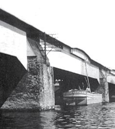
Union Bridge – under repair from Erie Canal boat looking towards Lansingburgh.
finest specimens of art which this country has produced; and in point of usefulness, we believe it is not exceeded by any; and it forms not only cheap but safe passage across the Hudson, and will, at no very distant period, undoubtedly become the grand thoroughfare from the eastern to the western country. The Troy Gazette, in its December 11 issue, was even more complimentary and almost poetic, writing:
It is with much pleasure (says the
Waterford Gazette) we announce the completion of the bridge at this place, which for architecture, strength and beauty, exceed, perhaps, any thing of the kind in the United States. On examination it will be found that its symmetry is just in all its parts, which reflected the highest honor on its engineer, Mr. Theodore Burr and when one beholds with what regularity and dispatch the plans of the architect have been executed by Mr. Samuel Shelly, under whose immediate superintendence the work has progressed we conceive no less praise to him is due. While we are also contemplating this noble structure let us descend beneath the waters and there fixing our minds on its rocky base gradually emerge from the stream, behold,
with wonder and admiration, three stately columns, whose strength appear to battle the destruction of time and whose magnitude cause the winds to murmur as they pass, and the waves to return in perpetual eddies upon themselves. Here we behold the skill of masonry exemplified in Mr.
James McElroy, under whose direction the pillars arose, and on whom much econium has justly been bestowed. The tolls included $0.30 for every four wheel pleasure carriage, drawn by four horses, $0.125 for every wagon and two horses, and $0.02 for every foot passenger. Its cost to build was only $50,000. In a period of seven months, Burr, McElroy and Shelly had built a 726-foot long bridge of arch supported trusses that far exceeded in length any truss or arched bridge in the United States at that time. Palmer was just finishing his Permanent Bridge in Philadelphia in late 1804, with its opening in early January 1805, but his bridge was in three spans with the longest being 195 feet. Later, after Palmer’s Permanent Bridge was covered, the Board of Directors in 1814 (after reconstruction) ordered that it too be covered. The covering and repair, possibly rebuilding, to the bridge between 1812 and 1814 cost $20,000. Horse drawn trolley cars used the bridge for many years, paying a yearly fee of $750 in the 1860s and later increased to $2,000 per year. Electric trolley cars started using the bridge in 1889 and heavier Hudson Valley interurban trolley cars weighing over 25 tons started to use the bridge around the turn of the century. A local newspaper reported, “1901, partly on account of the deterioration in the structure but largely to provide for the increased load of large interurban trolley cars. Extensive repairs, costing $28,000, were made to the bridge. Additional 4 x 7-inch strips were bolted to
StruWare, Inc
Structural Engineering Software
The easiest to use software for calculating wind, seismic, snow and other loadings for IBC, ASCE7, and all state codes based on these codes ($195.00). CMU or Tilt-up Concrete Walls with & without openings ($75.00). Floor Vibration for Steel Bms & Joists ($75.00). Concrete beams with torsion ($45.00).

Union Bridge, Engineering News 1889.
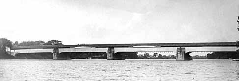
Union Bridge, 1804-1909.
the tops of the stiffener arches and intermediate rod hangers were put in to support additional floor beams.” Apparently 7 tiers of 4 x 8-inch strips were added to the two center spans and four tiers of the same size added to the shorter shore arches. The top chord bracing and roof structure was modified greatly to provide the necessary height for the trolley cars. The rebuilding was by Palmer C. Ricketts and Joseph Lawson of Rensselaer Polytechnic Institute. Engineering News wrote in 1889, “At the time the Waterford Bridge was built, therefore, it was the greatest existing wooden span in the world, and the first glance at the design shows that it was not only of a strictly original type but was a much more scientifically designed structure than any which had preceded it. For aught we know, it may be the greatest wood span which is standing today, so many of the short list of greater wooden spans having been burned or replaced by iron.” The magazine carried a full article on the bridge and its construction, thus bringing it to the attention of the engineering profession.
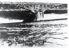
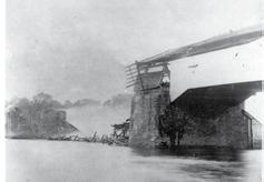
The bridge lasted until 1909 when it was destroyed by fire. The Troy Budget reported the “blazing bridge was a spectacle worth going miles to see.” Motorman
Walter Wright of the United Traction
Company was crossing the bridge when he “looked downward and saw a spiteful flame leaping from possible faulty insulation in the flooring. Soon the longcovered bridge, acting as an horizontal chimney, was blazing furiously.” This was followed by the separation of a gas main mounted to the bridge and, within a period of only 35 minutes, three of the four spans had collapsed into the river. Engineering News published two articles on the bridge after the fire. The first on July 14, 1909 by H. N. Peck of Boller and Hodge gave a brief history of the bridge and the plans for the new steel bridge. The second was a description of the fire by Oscar Hasbrouch, a Cohoes Civil Engineer, on July 22, 1909. A new steel bridge, designed by Boller and Hodge and fabricated and erected by the Phoenix Bridge Company, was erected on the same piers and stands today over 105 years after its construction. The two bridges, having a combined service life of 210 years on the same masonry piers, were designated as National Historic Civil Engineering Landmarks in 2013.▪
THE SAN FRANCISCO – OAKLAND BAY BRIDGE
By Ronald F. Middlebrook, S.E. and Roumen V. Mladjov, S.E.
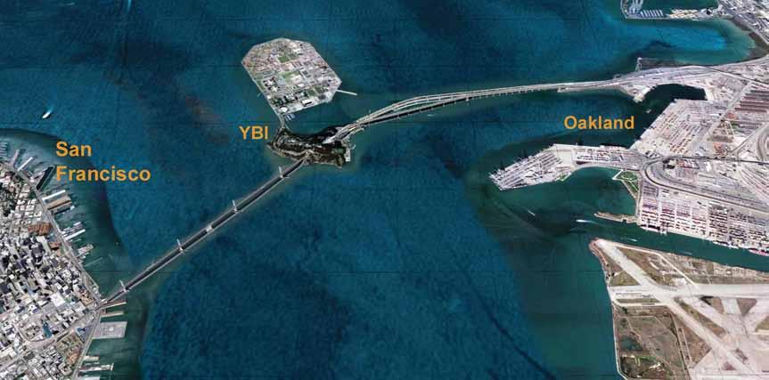
Figure 1: Bay Bridge with new east crossing.
The San Francisco-Oakland Bay Bridge is one of the greatest American bridges. Built during the Great Depression, the bridge soon became known as the “working horse of Northern California,” carrying the heaviest traffi c in the region.
General Information
Th e San Francisco – Oakland Bay Bridge opened to traffi c in 1936. It connects San Francisco and Oakland and is the busiest vehicular link in Northern California (Figure 1). Th e bridge is actually several structures with distinctly diff erent systems, strung together to form about a 8.5-mile (13.7-km) cross-bay roadway, nearly 4.4-miles over water (7.1km). Th e main portions of the original were: • West crossing: Nearly 2 miles (3,140 m) from San Francisco to
Yerba Buena Island (YBI), including a twin suspension bridge with central spans of over 2310 feet (704 m) (Figure 2). • YBI segment: 1800 feet (549 m) featuring a tunnel and short concrete viaduct.

President Herbert Hoover at the groundbreaking ceremony, 1933
• East crossing: A more than 2-mile (3,417 m) crossing from
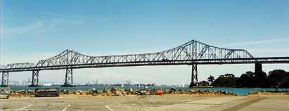
YBI to Oakland, consisting of several diff erent steel truss systems: four short (approximately 288-foot; 88 m) spans on YBI, followed by the 2420-foot-long (738 m) cantilever structure (Figure 3), then fi ve deep through-truss spans at 509 feet (155 m), fourteen deck-truss spans at 288 feet (88 m), and the remainder on simple land-based steel structures. Th e original bridge was designed by Ralph Modjeski, Charles Purcell et al. and built by American Bridge Company using steel from United States Steel. At the time of completion, it was the longest bridge in the world and featured the second longest suspension span (2310 feet; 704 m), the third longest cantilever truss span (1400 feet; 427 m), the deepest pier foundation (243 feet; 74 m) below water surface at low tide), and the largest bored tunnel. Th e west crossing was the only major bridge with two consecutive suspension spans. Th e bridge, with its three major segments, is listed on the National Register of Historic Places (NRHP). Th e Register’s comment is: “One of the largest and most important historic bridges in the country.”
BRIDGE ELEMENT Total Length miles (meters) Main Span feet (meters) Secondary Spans feet (meters) Traffic Lanes Vehicles per Day Construction Time (years) Completed Steel psf (kg/m2) Cost in US $ Millions 2.1 (3,377) 1400 (427) 509 (155) 10
280,000 3.5 1936 85 (416) 78 (not comparable) 2.2 (3,513) 1266 (386) 525 (160) 10
324,000 11.75
2013 347 (1,694) 6,450
President Herbert Hoover, who was originally a mining engineer, had followed the development of the design of the bridge during his presidency. He was particularly interested in its effect on employment in trying times. Calling this project, “The greatest bridge yet erected,” shows its importance to Hoover. The entire bridge deserves its exalted historic credentials, from the graceful sweep of the west crossing suspension structure, through the YBI tunnel and viaduct, to the steel cantilever truss section, to the through-truss and deck-truss spans. It was built in just 3½ years, at a cost then estimated at $78 million. It was, and still is, one of the greatest engineering achievements of the 20th century. (Caltrans) reported for building just the superstructure of the new east crossing replacement – 266,750 tons (242,000 metric tons), or 347 psf (1,694 kg/m2). A testament to the wisdom of the design for the Bay Bridge’s west crossing is that, 62 years later, Japanese engineers chose a very similar design for the towers of the longest bridge span in the world: the Akashi-Kaikyo (or Pearl) Bridge, with a central span of over 6530 feet (1,991m).
Earthquake Damage
Design and Construction
The bridge’s east crossing was locally damaged during the Loma Prieta earthquake of 1989. A 50-foot (15-m) section of the top deck slipped off its support at an expansion joint; that end of the section then collapsed onto the lower deck (Figure 4). One The Bay Bridge is a double-decker. The original design featured six motorist was killed. automobile lanes on the top deck (three in each direction). The bottom Caltrans subsequently decided to replace the entire east crossing, deck provided three truck lanes and two lanes (one in each direction) calling it an Earthquake Safety project; an important decision because for an interurban commuter train. Around 1960, the arrangement it meant that only the pre-existing traffic capacity would be restored. was converted to five eastbound lanes of traffic on the lower deck and After several years of discussion, planning and design, construction five westbound lanes on the upper deck. on the new east crossing finally began in January 2002, and it was The bridge was designed and built using state-of-the-art techniques completed in September 2013. available in the 1930s. For example, the engineers specified the higheststrength steel available for critical elements. Nickel (55 ksi; Grade 380 West Crossing Improvements MPa) and silicon steel (45 ksi; Grade 311 MPa) for the east crossing make up 62% of the total steel used there, and 72% of the cantilever and East Crossing Replacement section. Even the carbon steel used in this bridge was higher-strength The west crossing (and its approach) underwent seismic improve(37 ksi; Grade 255 MPa) than is normally used today. High-strength ments in a five-year project beginning in 1999, at a reported cost of cable steel (120 ksi; Grade 828 MPa) was specified for the west crossing approximately $759 million. The improvements included massive suspension cables. The entire bridge required 167,100 tons (151,593 rollers installed between the roadway and bridge supports and 96 metric tons) of structural steel, or 115 psf (561 kg/m2). new viscous dampers inserted at critical points to allow movement. The Bay Bridge and its neighbor, the Golden Gate Bridge (completed The bridge’s twin suspension spans were strengthened by adding new in 1937), represent the culmination of more than 100 years of devel- steel plates and replacing half a million original rivets with almost opment of bridge engineering and construction in the United States. twice that many high-strength bolts. New bracing was added under To fully appreciate the achievement of completing both decks, and all of the “laced” truss diagonals the construction so quickly, consider the technical connecting the upper and lower road decks were level of the industry at the time. In addition to replaced. In total, the project added about 8500 the lack of modern devices – heavy equipment, tons (7,710 metric tons) of structural steel. vehicles, cranes, etc. – all steel connections were The east crossing replacement was designed made using rivets, requiring much more time and by T.Y. Lin International, Moffat & Nichol labor than modern high-strength bolting and weld- Engineers, Weidlinger Associates and Donald ing. Compare this achievement with the 12 years MacDonald Architects. It is comprised of a singleit took to build the new replacement bridge just tower, self-anchored suspension steel span of 1266 for the east crossing! feet (386 m) and a 14-span (525 feet; 160 m each) Amazingly, the 167,100 tons (151,593 metric concrete skyway. The new crossing has added tons) of steel used for the entire Bay Bridge in shoulders and a bicycle lane. (Since there is no 1936 is considerably less than the tonnage that bicycle lane on the west crossing, it will not be the California Department of Transportation Figure 4: Local damage to the east crossing. possible to bike the entire length of the bridge.)
The cost is about $6.5 billion for a length of nearly 2.2 miles (3,513 m). Current plans are to demolish all of the original east crossing structures from YBI to Oakland, and presumably recycle as much material as possible. Demolition is currently estimated to cost at least $250 million. Comparing the two east span bridges – the original (1936) and the replacement (2013) – gives an idea of the efficiency of the old bridge (see Table, page 27).
Traffic Capacity and Population Demographics
With only five traffic lanes in each direction, traffic movement is greatly compromised, especially during commute hours. Traffic capacity has remained the same from 1960 to 2012 and is no different with the east crossing replacement. In 1936, the Bay Area population was about 1,650,000. By 1990, it was about 6,024,000, and by 2010, it was 7,150,000. The projected population in 2025 is 8,880,000, rising to 9,031,500 in 2035 (50% greater than in 1990). Traffic growth has been even more rapid. When the bridge originally opened in 1936, the traffic equivalent was 50,000 vehicles. As early as 1947, Frank Lloyd Wright called the traffic congestion on the Bay Bridge intolerable. By the late 1990s, this critical highway link carried about 280,000 vehicles on an average day. In 2000, it was evaluated as 324,000 vehicles on average. In other words, the growth in demand has increased nearly six-fold over the past 75 years. Currently, during commute hours it can take up to 30 minutes to drive the 4.4 miles (7.1 km) from water’s edge to water’s edge across the bridge. That translates to only 9 miles per hour (14 km/h), and sometimes it is even worse, especially if there is an accident on the bridge. The idea of supplementing traffic capacity across the bay is not new. Numerous studies over the past 60 years have been conducted for new crossings (both bridges and tunnels). None of these studies were pursued, for environmental, political, economic and other reasons. However, these efforts show a great deal of continuing interest in reducing the pressure on cross-bay traffic.
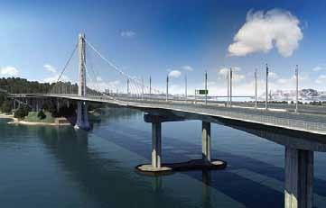
Figure 5: New east crossing: Skyway and self-anchored suspension bridge (SAS). Courtesy of MTC and Caltrans.
Seeking a rational solution for this “problem,” some of the possibilities include: • Expanding Bay Area Rapid Transit’s (BART) underwater, cross-bay tunnel. BART has already reached its maximum capacity during peak commute times. Enlarging the system would be fraught with technical difficulties, high cost and environmental problems. • Adding more ferries. The Bay Bridge ended the ferry system era long ago. Ferries imply more automobiles to get to and from the water’s edge. This would be a giant step backward. • Adding a second bridge parallel to the existing Bay Bridge.
This idea has already proven more practical in other cities around the world. Considering these limited options, a second bridge seems to be the most logical approach to solve the restricted capacity of the existing bridge. Considering the fact that the replacement of the old East crossing structure took more than 17 years, now is the time to begin planning and designing a completely new second SFO Bay Bridge alongside the present one using the retrofitted, old east crossing structures. The Structural Forum column in this issue (page 50) summarizes the argument for this course of action.▪
T I M B E R B R I D G E S
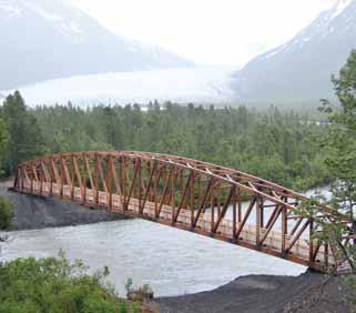
At 280 feet long, this camelback truss bridge is the longest clear-span timber bridge in North America. Designed and fabricated in our shop, the bridge provides passage over the Placer River into the Chugach National Forest in Alaska.
DESIGN • SUPPLY • DELIVER • INSTALL (800) 547-5411
Ronald F. Middlebrook, S.E. (ronfranco@gmail.com), is retired from Middlebrook + Louie in San Francisco, California, and is a Past President of the Structural Engineers Association of Northern California (SEAONC). Roumen V. Mladjov, S.E. (rmladjov@louieintl.com), is a Senior Associate with Louie International in San Francisco, California, and was a member of the Engineering and Design Advisory Panel for the Bay Bridge.
A similar article appeared in the IABSE Conference Rotterdam Report, May 2013. The online version of this article contains detailed references. Please visit www.STRUCTUREmag.org.
i ntro D ucing the HoW/2
Serie S by SDS /2
true connection DeSign, not SimpLy connection veriFicAtion
SDS/2 is the only system that provides true connection design — for individual members, as well as all interacting members in a structural joint.
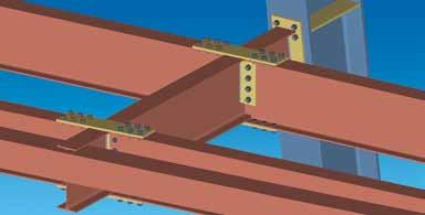
FuLL Joint AnALySiS
Instead of choosing a connection from a library, SDS/2 designs the connection for you, based on parameters that you establish at the beginning of a project.
All connections SDS/2 automatically designs will comply with the connection design code standards the user chooses.
learn more
Want to see how simple it really is to design connections in SDS/2? Scan the QR code to watch SDS/2’s connection design in action.
Design ConneCtions
with SDS/2
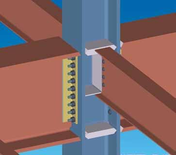
compLete connection DeSign reportS
SDS/2 provides long-hand calculations of all designed connections, which simplifies the verification process. Scan the QR code to view an example of SDS/2’s automatically generated calculation design reports.
cLASh prevention
SDS/2 checks for interaction with other connections within a common joint. That means adjusting connections for shared bolts, checking driving clearances for bolts, sharing, adjusting and moving gusset and shear plates when required, and assuring erectablity of all members. All adjusted connections are automatically verified based on selected design criteria.
the TRanSFoRmaTion of the HiSToRiC FiRST naTional
STaTE Bank BUilding
Newark New Jersey – Part 1
By D. Matthew Stuart, P.E., S.E., F.ASCE, F.SEI, SECB, MgtEng and Ed D. Cahan, P.E., S.E.
More than 100 years after its original construction in 1912, the First National State Bank Building in Newark, New Jersey (Figure 1) is ready to return to prominence. Located near the intersection of Broad and Market Streets, one of America’s busiest intersections just after the turn of this century, the rehabilitation of this structure is paramount to the ongoing revitalization of Newark’s historic commercial and business district known as the “Four Corners”. The structure consists of a 12-story mid-rise building with concrete slabs, steel I-beams and built-up steel columns; an adjacent three-story addition with concrete slabs and steel W-shape beams and columns constructed at an unknown date; and a more recent four-story structural steel, masonry block and brick stair and elevator tower at the very rear of the property.
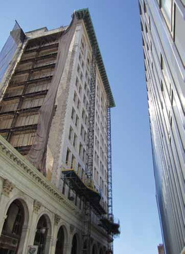
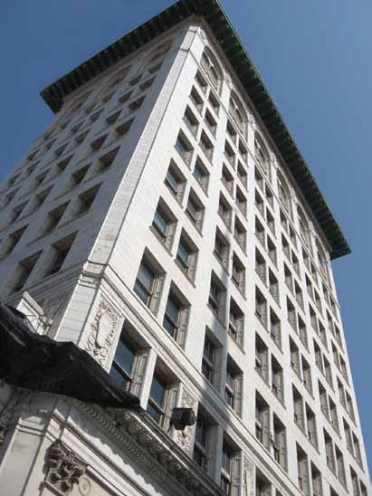
Figure 1: Existing façade prior to renovations.
The facility was originally designed as a bank and office building; however, in recent years most of the upper floors remained vacant while the ground floor was used occasionally by retail and office tenants. The developer engaged Pennoni Associates Inc (Pennoni) to perform the structural engineering services required to transform the building into a mixed-use facility consisting of a hotel with restaurant, dining, and retail spaces. These services included designing a two-story overbuild above the existing three-story addition, designing a nine-story stair and elevator addition at the rear or east side of the footprint of the existing 12-story structure, strengthening the existing roof structure above the 12th story to support an occupied terrace, and several other structural modifications required to complete the overall adaptive reuse. Designed by prominent American architect Cass Gilbert, whose other works include the Woolworth Building in New York City and the United States Supreme Court Building in Washington, D.C., the First National State Bank Building is a classic example of “skeleton” construction, for which Gilbert was one of the earliest pioneers. Skeleton construction consists of a primary steel frame directly supporting exterior brick walls as a non-load-bearing cladding system. This method of construction formed the basis for modern high-rise construction methods still employed by engineers and architects today, and served as an advancement of the “cage” method of construction. Cage construction involved steel frames supported by steel columns with thickened exterior brick walls that supported their own selfweight, similar to the previous method of using exterior brick walls to support the adjacent floor framing. In order to support the exterior brick cladding on the steel frame, the structure of the First National State Bank Building utilized a double spandrel beam in which the interior member supported the
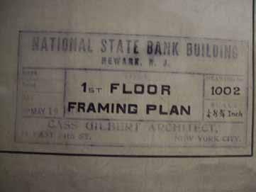
Figure 3: Cass Gilbert drawing titleblock. Figure 4: Cass Gilbert drawing 1st fl oor framing.
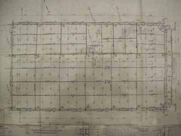
adjacent fl oor framing and a small portion of the exterior brick cladding, while the exterior member supported only the exterior brick cladding (Figure 2). Both spandrel beams framed to, and were supported by, the same steel column, but the exterior member required an extended single plate shear connection because it did not align with the column centerline. Due to the historical signifi cance of many of the structures designed by Cass Gilbert, structural drawings of many of his buildings, including the First National State Bank Building, have been preserved by the New York Historical Society as well as the Library of Congress. In addition, the original mid-rise structure and the adjacent low-rise addition were added to the National Register of Historic Places in 1977. Th e structural drawings were prepared on linen sheets, and due to their age and fragility, the New York Historical Society would not allow the drawings to be removed from their offi ce for reproduction purposes. Th erefore, each drawing sheet was laid out on a table at the Historical Society’s offi ce and photographed for future use in analyzing the existing structure for the required modifi cations. Th e fi rst step was taking a photograph of an overall drawing, followed by taking closeup photographs of portions of the same drawing that could be laced together in sequential order so that the entire drawing could be viewed in greater detail at Pennoni’s Philadelphia offi ce (Figures 3 and 4). Th is
Tedds2013 Now available and packed with exciting new features
adVERTiSEmEnT–For advertiser information, visit www.STRUCTUREmag.org
Automate your daily structural calculations and change your world.
Working with Tedds you can now analyze frames, use a broad library of calculations, create high quality, transparent documentation, and even write your own calculations.
You can: You will:
Use a broad library of calculations Write your own calculations Work within Microsoft Word Analyze frames Produce transparent output Archive documents electronically Save time & increase profit Reduce calculation errors Improve consistency Reduce overheads Enhance QA processes Go online to download your free Tedds trial

877 710 2053 (Toll Free) www.cscworld.com
#cscworldglobal
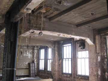
Figure 5: Existing encased bent prior to renovations.
process was repeated until the entire set of original drawings, including all notes, schedules, and details, were photographed. A review of the drawings revealed that the second floor of the mid-rise building was originally constructed as a mezzanine area overlooking the first floor lobby below. However, at some time during the life of the building the remaining portion of the second floor was infilled with steel and concrete framing similar to the original structure. Existing drawings for the infill framing were not available. Extensive field investigations were still necessary in order to supplement missing information on the structural drawings, and to confirm that the members shown on the drawings were actually in place. Structural drawings were not available for the low-rise addition, so more extensive field investigations were required in order to determine the structural members for this portion of the building. In both portions, steel beams were encased in concrete and steel columns were encased in hollow clay tile blocks, a common method of providing fire protection during the early 20th century (Figure 5). The concrete and clay tile encasements were removed from a portion of the beams and columns in order to perform the field investigations. Physical properties of selected steel beams and columns were measured, then compared to the physical properties of steel beams and columns in two AISC published databases for historic shapes and specifications in order to verify that the members shown on the existing structural drawings were in fact used in the actual construction. AISC databases were also used in order to establish the yield strength of the steel at the time of fabrication; however, steel coupons were also taken from beams at various locations in both the mid-rise and the low-rise buildings in order to determine the chemical and material properties of the steel, including weldability and actual yield strength. Finally, concrete cores were taken in several locations in order to verify the thickness, unit weight, and compressive strength of the slabs. Locations chosen for the concrete cores included the roof of the mid-rise and low-rise buildings in order to determine if topping slabs were present to provide drainage, and at the typical floor in both the mid-rise and low-rise buildings to determine the slab construction. The results of the field investigations, in conjunction with available structural drawings, were used to determine the structural capacity of the existing building. The renovation of the low-rise building called for a two-story addition consisting of hotel rooms and a rooftop terrace. The first challenge encountered was the need to recess the north face of the vertical
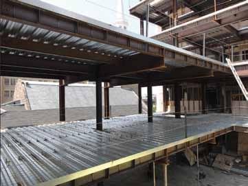
Figure 6: 4th & 5th floor addition north elevation cantilevers.
extension from the existing north elevation of the original facility because of a National Register of Historic Places and State Historic Preservation Office (SHPO) requirement not to alter the sightlines of the building as viewed from Broad Street. As a result, the north exterior wall of the new addition was set back from the north exterior wall of the existing low-rise below. The existing interior and exterior columns along the south exterior wall were used to support the new addition, but a large cantilever at the new fourth and fifth floors was required to support the portion of the addition on the north side of the interior column line (Figure 6 ). Excessive deflections at the cantilever were mitigated by using an upward camber equal to the total dead load deflection, and by providing slightly deeper members than those required for strength design only. A second challenge encountered with the design of the 2-story addition was determining the capacity of the existing columns and foundations that would be required to support two new floors. Using the physical column properties measured during the field investigations and the mechanical properties established via the steel coupon testing, the columns were determined to have significant reserve capacity based on their unbraced lengths and the loads applied by the three existing framed floors. In fact, it was determined that the low-rise building had been designed for a full 12 stories to match the high-rise tower, but the construction had stopped at the third floor, which then served as a roof over the second floor. This conclusion was confirmed during demolition of the clay tile providing fire protection around the low-rise columns and further investigation of the existing topping slab on the low-rise roof. At these locations, the existing columns were found to have bolt holes in their webs and flanges to accept splice plates for future columns above. Part 2 of this article will appear in a future issue and will discuss renovations associated with life safety improvements and enhancements to the space utilization of the 12th floor and roof.▪
D. Matthew Stuart, P.E., S.E., F.ASCE, F.SEI, SECB, MgtEng (MStuart@Pennoni.com), is the Structural Division Manager at Pennoni Associates Inc in Philadelphia, Pennsylvania. Ed D. Cahan, P.E., S.E. (ECahan@Pennoni.com), is a project engineer with Pennoni Associates Inc in Philadelphia, Pennsylvania.
