
28 minute read
rainbows only Come after rain


Professional issues
issues affecting the structural engineering profession
Forming a Young Members Group (YMG) has altered my professional vision and influenced the lives of many others. In 2010, shortly after attaining my master’s degree, I joined the Structural Engineers Association of Massachusetts (SEAMASS) and have been actively involved ever since. However, I soon noticed that there were hardly any young registered members or event attendees. Observing other young professionals in my network, I noticed that young engineers lacked a cohesive network of resources which we could use to seek answers to entry level questions (which some find difficult to ask at work), and have our opinions and concerns addressed through an established avenue. In 2012, Sofia Zamora and I took the initiative to establish a Young Members Group of SEAMASS, with the goal of supporting young engineers in the Massachusetts structural engineering community, particularly in aiding their transitions from school to professional life. Establishing a new group Rainbows Only Come After Rain was quite a challenge, but not nearly as difficult as justifying the importance of the YMG to the local structural engineering The Importance of a community. We found that this initial position Young Members Group was somewhat common among other NCSEA state affiliates. I am sure that there remain some By Ellen (Chuan-Hua) Kuo, P.E., LEED AP BD+C who believe that a YMG cannot contribute as much to the profession as senior members, and it is my goal to change their minds. As the SEAMASS YMG continued to thrive, members of the SEAMASS Board applauded our efforts and achievements, and began to embrace the germination of a reciprocal relationship. Upon receiving proposals from the YMG, SEAMASS Ellen (Chuan-Hua) Kuo, P.E., has been investing in us, allowing us to explore LEED AP BD+C, is a structural different group activities, host creative topics that engineer with Symmes Maini & are geared toward young professionals, and build McKee Associates in Cambridge, a vibrant community for the future. SEAMASS Massachusetts. She is Co-Founder YMG creates avenues for young members to grow of SEAMASS YMG and the in areas outside of the customary technical preResource Guide Administrator sentation setting. of NCSEA YMG Support We want to further prepare young engineers Committee. She may be reached for their careers in many aspects in addition to at ekuo@smma.com. technical knowledge. SEAMASS YMG provides hands-on learning experiences, such as touring facility plants and construction sites, training programs and study groups, community outreach opportunities, as well as soft-skills building. Many of the young engineers that come to YMG events to network and learn in a more casual environment ultimately become a part of the team, further benefiting the member organization (MO). Not only does the member organization benefit from the increased number of members and a great contribution of novel ideas from the YMG, but also senior board members of the MO receive new perspectives and creative concepts that inspire them to reevaluate the longstanding status quo and organizational approach. Society is often resistant to change, and some organizations may be hesitant to implement new plans – in this case, a new committee group. In the start-up stage, there are hurdles that must be overcome by both the established senior members and the joining young members. Convincing others to believe in us and to fight this uphill battle can be difficult. That said, we, both senior and junior members, must be resilient and perseverant if we wish to build something truly significant.
A Reciprocal Relationship (Mentorship)
I believe that a reciprocal relationship is just one of many advantages created from establishing and maintaining a YMG. In the structural engineering context, reciprocal relationships allow young engineers to apprise senior engineers of the latest industry trends and new methods, while senior engineers continue to foster the professional development of young engineers in the traditional mentorship mold. In order to properly implement reciprocal mentorship, we must first ask ourselves, “How is the industry different today from what it was in the past?” The college curriculum for the LRFD generation varies considerably from the curriculum of the ASD generation 20 years ago, when those who are now the experienced, senior engineers received their educations. Many experienced engineers adopted the rule-of-thumb methods that they learned from their own mentors and practice with formulas from old codes, shortening design times while staying adequately conservative. However, methods that were once commonly used are no longer efficient today, or applicable to modern structural shapes and the constantly changing codes. Reciprocal mentoring would help to bridge the knowledge gap between generations of engineers, allowing both parties to increase their knowledge base. Younger engineers could brief the experienced engineers on the latest design technology options and industry trends, while simultaneously learning to ply their trade from the more experienced minds. This relationship would lead senior engineers to consider more factors (such as unforeseen software constraints and limited resources) when they estimate project budgets and required hours. Consequently, accurate projections would increase the efficiency and competitiveness of their work. In return, young members will receive lessons learned from individual senior engineers and collective structural knowledge within the MO.
The focus of nurturing a young community, which is oftentimes undervalued or overlooked, is the key to a better future. It is very important for experienced engineers to be aware of the frustration that exists in the industry today – acknowledging the dynamic role of today’s young engineers and the importance of their roles in the structural community. Planting the YMG seed is one solution to sustain the growth of engineers, to increase competency and competitiveness in the industry, to develop leadership and management skills early, and to learn what it takes to create and complete a job. Young members should no longer be thought of as just individuals taking up seats in the structural community; rather, they should be thought of as individuals with extensive, growing networks who exchange information and cultivate one another to be future leaders. At the 2014 NCSEA conference held in New Orleans, the regular attendees must have noticed an obvious change in the NCSEA community. There were 10 times more young professionals attending the conference compared to just two short years ago. In addition, the NCSEA Young Members Group Support Committee was in charge of one of this year's conference sessions, deliberating challenges that the industry is facing, recommending strategies to mitigate them, and working together to solve problems. Great things take time and energy to bring to fruition. With support and guidance from the community, this LRFD generation will soon be capable of assessing, creating, and forecasting new solutions and opportunities for development of a greater community, and to further improve the practice and the standard of this profession. By planting the seeds now to germinate tomorrow’s success, we ask you to help us grow the YMG network, so that those who are following in your footsteps can receive some of the advantages that you can only wish you had. The successful launch of the Young Members Group of SEAMASS was due in large part to the resources and guidance offered by the NCSEA Young Members Group Start-Up (Resource) Guide. The 2014 version of the NCSEA YMG Resource Guide, compiled by Heather Anesta (heather.anesta@stantec.com) and Ellen Kuo (ekuo@smma.com), can be found at www.ncsea.com/resources/documents. We look forward to hearing your feedback and suggestions about the Young Members Group!▪
State-of-the-Art Products
STRUCTURAL TECHNOLOGIES provides a wide range of custom designed systems which restore and enhance the load-carrying capacity of reinforced concrete and other structure types, including masonry, timber and steel. Our products can be used stand-alone or in combination to solve complex structural challenges.
V-Wrap™
Carbon Fiber System
DUCON®
Micro-Reinforced Concrete Systems
VSL
External Post-Tensioning Systems
Tstrata™
Enlargement Systems
Engineered Solutions
Our team integrates with engineers and owners to produce high value, low impact solutions for repair and retro t of existing structures. We provide comprehensive technical support services including feasibility, preliminary product design, speci cation support, and construction budgets. Contact us today for assistance with your project needs.
www.structuraltechnologies.com +1-410-859-6539
To learn more about Structural Group companies visit www.structuralgroup.com DUCON® trade names and patents are owned by DUCON GmbH and are distributed exclusively in North America by STRUCTURAL TECHNOLOGIES for strengthening and force protection applications. VSL is the registered trademark of VSL International Ltd.
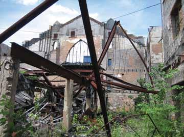
Figure 2.
Bethel Missionary Baptist Church was founded in the nineteenth century by Reverend Jack Yates, an early leader of Houston’s African American community. Located in Freedmen’s Town, a post-Civil War Houston neighborhood founded by freed slaves, the church was the first constructed by former slaves, with the earliest portion constructed in the 1890s. The first two church buildings were destroyed, and in 1923 a third single story church building was erected. In 1950, second and third stories were added. The sanctuary was designed by James M. Thomas, a prominent architect of African American churches. In January 2005, a fire gutted the interior of the historic structure, collapsing the interior framing and roof, leaving only the exterior masonry walls in place. The structure sat exposed and abandoned until 2009, when the City of Houston purchased the property to convert the former church into a community park (Figure 2). The remaining walls consist of two distinct constructions. The 1923 single story is a reinforced concrete frame in-filled with structural clay tile with a brick veneer. These walls were present at the base of the east, west, and south walls. In 1950, when the second and third stories were added, the north wall of the building was re-clad with a concrete masonry unit (CMU) and brick cavity wall system, and the new north façade was increased to a height of 50 feet. The CMU and brick cavity walls were also constructed on top of the existing 1923 walls on the east, west, and south elevations during the 1950 renovation.
Before Restoration, Protection
Walter P Moore of Houston, Texas, was initially retained to provide nondestructive testing services to evaluate the conditions of the existing masonry walls and develop strengthening solutions as necessary. However, once an initial site visit was conducted, the first challenge of the project became evident; access into the site to evaluate the masonry walls was nearly impossible due to the collapsed framing and debris that still remained from the 2005 fire, and a large crack in the 50-foot tall brick veneer running from the base of the wall to the top was visible at the northeast corner of the building (Figure 3). The deteriorating façade immediately adjacent to the pedestrian sidewalk posed a potential risk to public safety. Before any assessment could be performed, the engineering team made recommendations to the City to immediately close the street to traffic and temporarily brace the existing walls. Emergency shoring and bracing was designed and installed within a 24-hour period to protect the public and the structure.

Figure 3.
Determining Basis for Design
The biggest challenge in any restoration project is developing information about unknown conditions. Once the walls were stabilized, a comprehensive visual condition assessment was performed to document the distress conditions for repair and understand the wall construction. Given the fire-damaged state of these walls, understanding the appropriate masonry strength to use in design was fundamental. A combination of flat-jack tests and unit compressive strength tests were utilized to determine the masonry material capacities needed for design. Flat jack testing is a nondestructive technique where masonry compressive and shear strengths are evaluated in-situ. When measuring compressive strengths, the test consists of routing out a horizontal mortar joint to allow a calibrated steel bladder to be inserted into the joint. For shear strength tests, a vertical joint is tested. Linear variable differential transformers (LVDTs) are mounted to wall surface and the bladder then “inflated” hydraulically (Figure 4). The hydraulic pressure and displacements are measured and a stress-strain relationship is developed. The laboratory testing data showed that the historic brick had a compressive strength of 1,600 psi. The modern brick in the building had a compressive strength of 2,000 psi, which is consistent with the minimum compression strength for Grade S-I, S-II bricks, while

Grade N-1 and N-2 bricks commonly used in modern construction have a minimum compressive strength of 3,000 psi. In historic preservations, the designer always has to specify materials that conform to, or are as close as possible to, those used in the original construction. For this project, it was anticipated that repointing deteriorated mortar joints would be necessary, so a mortar analysis was performed. Three mortar samples were excised from the structure and analyzed by acid digestion of the binder and sieve analysis of the aggregate in accordance with ASTM C136. This analysis determined the starting proportions for the mortar specified in the design documents should be 1: 1¼: 5½ (Portland cement : lime : aggregate). In addition, the color and gradation of the mortar aggregate were determined, which allowed the contractor to closely match the original mortar properties and aesthetics (Figure 5).
Wall Strengthening in Plain Sight
The engineering assessment program determined that the CMU back-up walls and structural clay tiles were in poor condition as a result of the fire, resulting in a dangerous condition. Significant cracking was evident throughout the back-up wall system, and large portions of the wall were unreinforced, including the 50-foot tall north wall. At several locations, the brick ties that anchor the brick veneer to the back-up wall, installed during the 1950 construction, had corroded and failed. Failure was likely prior to the fire and was due to the age of the building, but resulted in veneer that was separating from the back-up. In keeping with the historic nature of the walls, a strengthening solution had to be designed that would not alter the existing aesthetics and
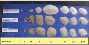
Figure 5.
would minimize the extent of replacement in the building veneer. To accomplish this objective, the design team proposed a galvanized steel frame that would visually recall the original gabled roof lines of the church, with new metal panels and poly-resin glass panels installed in the existing windows and door openings (Figure 1, page 34). The existing walls would have to be strengthened to span between the girts of the new frame for the loads imposed by the 110-mph hurricane wind speeds required by the building code (IBC 2006 modified with City of Houston amendments). This design requirement alone would be challenging enough for a heavily damaged masonry structure. However, because the walls themselves would be exposed and without interior finishes, strengthening would need to be “hidden in plain sight” to community park patrons while not visibly altering the appearance of the walls. The design team developed a repair solution that consisted of strengthening of the back-up wall and pinning the existing brick veneer to the strengthened back-up. With this strengthening accomplished, a ferrocement finish was
ADVERTISEMENT–For Advertiser Information, visit www.STRUCTUREmag.org
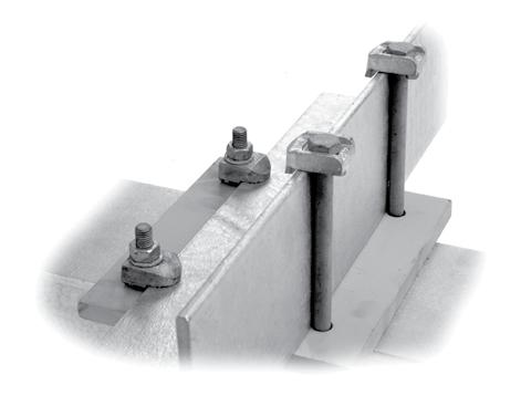
Connect Steel to Steel without Welding or Drilling
• Full line of high-strength fasteners • Ideal for secondary steel connections and in-plant equipment • Easy to install or adjust on site • Will not weaken existing steel or harm protective coatings • Guaranteed Safe Working Loads • Corrosion resistant
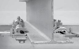
FloorFix and Grating Clip secure raised or open floors and grating. We manufacture ICCES certified BoxBolt® for HSS blind connections. FastFit universal kits for faster and easier steel connections.
NEW!
A KEE SAFETY COMP ANY
applied that provided additional strengthening and added to a clean appearance for the interior of the park. At the base of the walls in the 1923 construction, a new, reinforced CMU back-up wall was constructed to “sandwich” the existing structural clay tile in-fill; removing this infill could have potentially compromised portions of the wall supported above it. Stainless steel helical anchors were then driven through the existing veneer, the existing structural clay tile, and into the new back-up wall beyond. In the 1950 construction, the existing CMU back-up walls were reinforced by removing the interior shell of the CMU and grouting in new vertical reinforcing bars doweled into the existing grade beams. Large cracks in the existing CMU back-up were reinforced by routing out the horizontal grout and installing stainless steel helical ties across the crack. Once this crack reinforcement was installed, the grout line was re-pointed and the crack itself was then grouted. Cracks through the exterior brick were also treated in this manner, and the brick veneer then pinned using helical anchors back to the strengthened back-up wall. A ferrocement coating was then applied to provide lateral reinforcement to the CMU back-up wall and provide a uniform finish to the interior of the park walls (Figure 6 ). Galvanized welded wire reinforcement was pinned to the interior faces of the walls, and a 2-inch thick shotcrete coating was applied. At window openings and the tops of the walls, the ferrocement coating was extended around the edges of the openings to provide clean and aesthetically pleasing terminations. The ferrocement was given a drag finish for a relatively smooth wall surface that resembled a stucco wall finish. A cream colored elastomeric finish coating was specified by the design team to brighten the interior finish and contrast against the new multicolored fenestrations.

Figure 6. While this strengthening ensured that the historic walls would stand through the hurricanes that are possible in the Houston area, a number of other details were required to enhance the appearance of the park and preserve key architectural elements of the walls. Cast stone panels installed in the north wall required patches to repair spalls and restore these panels. Existing lintels over door and window openings in the 1923 construction were removed and replaced since corrosion of the original lintels had resulted in rust-jacking and cracking. Once construction began, it became evident that each wall opening varied from the next. Each new fenestration required special detailing to connect to the existing walls. To anchor the new window and door panels, structural clay tile had to be removed between the new CMU
Servicing the Steel Industry For Over 75 YEARS
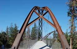
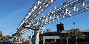
Museum of Flight Sea le, WA.
ADVERTISEMENT–For Advertiser Information, visit www.STRUCTUREmag.org
Toll-Free: (866) 252-4628 12080 SW Myslony St. Tualatin, OR 97062 info@albinaco.com www.albinaco.com YOUR BENDING EXPERTS
-Angle -Flat Bar -Square Bar -Wide Flange -Channel -Square Tubing -Tee -Rectangular Tubing -Round Tube & Pipe -Round Bar -Rail -Plate
Happy Hallow Park & Zoo San Jose, CA. Dry Creek Bridge Denver, CO.

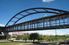
BART Rapid Transit Oakland, CA.

back-up wall and the existing brick veneer. Helical anchors were then installed between the brick and the CMU back-up, and the cavity filled as a part of the ferrocement construction. This provided a solid substrate into which anchors for the new panels could be installed. Coordination between the City, the design team and the contractor was a fundamental component to successfully delivering this project. Mock-ups of the ferrocement installation, coatings, and window terminations were constructed at key milestones in the project. These mock-ups allowed the design team and the Owner to meet, and review with the Contractor, issues related to aesthetics and constructability before getting approval by the Owner and design team. In addition, routine field observations by the design team throughout construction identified unknown conditions and developed alternate repairs and details as needed. All told, the construction lasted just over one year, with the ribbon cutting for the new park on December 15, 2013. The completed Bethel Park features concrete and brick walkways, installation of an artificial turf interior courtyard, and site amenities including raised fountains, seat walls, benches, lighting, fencing, landscaping and irrigation. A particular highlight of the park is the historic education panels mounted throughout the space.
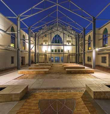
Figure 7.
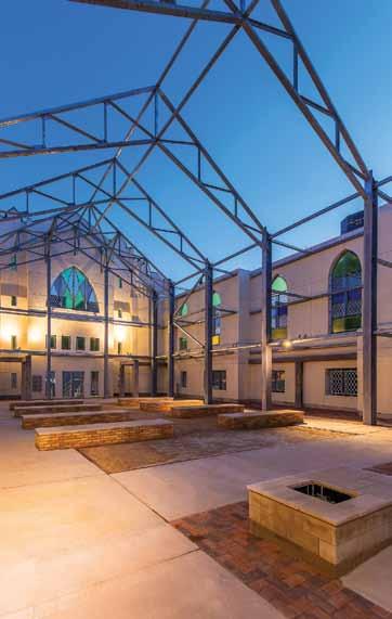
Conclusion
Severely damaged by fire, abandoned, but not forgotten by its community and congregation, Bethel Park preserves an important part of Texas and African-American history. Preserving heavily damaged, unreinforced masonry walls, protecting the public safety, and creating a new community space in which the original church walls were integrated were significant challenges for the design team. The unique strengthening techniques made it possible to have exposed masonry walls that contribute to the overall park aesthetic (Figures 7 and 8). The total project cost with property acquisition, bracing, design and park development was $4.7 million. The cost of strengthening the structure was $2.1 million, about half the total construction cost.▪
Jacob Bice, Ph.D., P.E., is a Senior Associate and Senior Project Manager in Walter P Moore Diagnostics Group. Dr. Bice conducts structural health monitoring and nondestructive evaluations such as GPR, impact echo, impulse response, UPV and half-cell corrosion potential on existing structures. Jacob can be reached at jbice@walterpmoore.com. Dilip Choudhuri, P.E., is a President and CEO of Walter P Moore Diagnostics. Dilip can be reached at dchoudhuri@walterpmoore.com.
Project Team
Owner: City of Houston – Parks Department, Houston, TX Structural Engineer for Masonry Wall Repairs: Walter P
Moore, Houston, TX Structural Engineer for Structural Steel Framing: Henderson + Rogers, Inc., Houston, TX Architect of Record: PGAL, Houston, TX General Contractor: JE Dunn, Houston, TX Masonry Subcontractor: United Restoration & Preservation,
Houston, TX Landscape Architect: White Oak Studios, Houston, TX
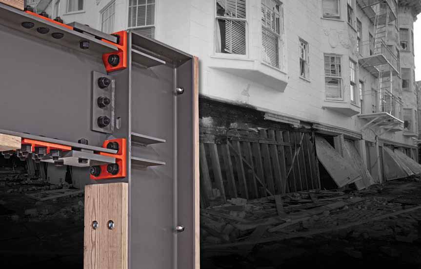
Retrofi t Solution for Soft-Story Buildings

Thousands of San Francisco building owners are now required by law to seismically retrofi t multi-unit (at least fi ve) soft-story, wood-frame residential structures that have two or more stories over a “soft” or “weak” story.
These buildings typically have parking or commercial space on the ground fl oor with two or more stories above. As a result, the fi rst fl oor has far more open areas of the wall than it actually has sheathed areas, making it particularly vulnerable to collapse in an earthquake.
That was the case in both the Loma Prieta and Northridge earthquakes, which is why cities in California, including Berkeley and Oakland, have recently passed similar legislation and many others, including Los Angeles, are now considering it. San Francisco’s ordinance affects buildings permitted for construction before January 1, 1978.
One solution to strengthen such buildings is the Simpson Strong-Tie® Strong Frame® special moment frame. Its patented Yield-Link™ structural fuses are designed to bear the brunt of lateral forces during an earthquake, isolating damage within the frame and keeping the structural integrity of the beams and columns intact.
“The structural fuses connect the beams to the columns. These fuses are designed to stretch and yield when the beam twists against the column, rather than the beam itself, and because of this the beams can be designed without bracing. This allows the Strong Frame to become a part of the wood building and perform in the way it’s supposed to,” said Steve Pryor, S.E., International Director of Building Systems at Simpson Strong-Tie. “It’s also the only commercially-available frame that bolts together and has the type of ductile capacity that can work inside of a wood-frame building.” Another key advantage of the Simpson Strong-Tie special moment frame is no fi eld welding is required, which eliminates the risk of fi re in San Francisco’s older wood-framed buildings.“Field welding is not a good thing, particularly in an existing building because the chance of fi re is just too great. A bolted solution is much safer.”
The special moment frame has been recognized in the construction industry for its innovation. It was one of only 16 products selected to win a 2014 Parade of Products@PCBC award, given by the California Building Association.
Soft-story retrofi t using Strong Frame® special moment frame For more information about the Strong Frame special moment frame, visit the website at
strongtie.com/strongframe.
Watch a video about San Francisco’s retrofi t ordinance at strongtie.com/softstory.
CFS Transforms Octagonal Structure into Elliptical Curve
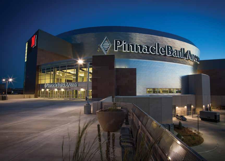
Pinnacle Bank Arena, Lincoln, Nebraska
By Jeff rey Kreinke, P.E., S.E., Karl Scherzer, P.E. and Jamie John, E.I.T.
Through the use of cold formed steel (CFS) framing, the corners of a rigid polygonal concrete structure can be smoothed and transformed into the gentle curve of an ellipse, enlivening the architect’s vision and creating a landmark structure in an up-and-coming neighborhood.
Figure 1. Pinnacle Bank Arena rendering.
Project Overview
Constructed as part of Lincoln’s West Haymarket Redevelopment Project, the new Pinnacle Bank Arena was completed August 2013. Th e 470,400 square foot multi-use event complex will not only serve as the new host for the University of Nebraska’s men’s and women’s basketball games, but also as a venue for year-round entertainment. Concerts, touring acts, and family productions will utilize the arena’s three public concourses and seating capacity for up to 15,900 guests. Th e new indoor arena is a seven level concrete structure wrapped in a metal panel and glass curtain wall façade. Th e inner, octagonal concrete super structure is enclosed by cold formed steel framing, which transforms the outer shape into a tri-radial ellipse. Th e facility combines “space-frame” panelized walls at the upper collar section with “stick-framed” walls at the lower collar area. Adjacent CFS framing with long span sloping walls were also “stick built” due to size and site constraints.
Various architectural design considerations, structural requirements, and construction obstacles had to be addressed throughout the cold formed steel design process to keep the project on schedule and on budget: • Tri-Radial Elliptical Façade • Panelized Space Frames • Special Construction Loading Requirements • Sloping Wall Studs • Staggered Openings at Bypass Wall Conditions • Connection Requirements • Large Duct Opening within Space Frame Panels The use of cold formed steel space frames was determined to be the best method to accommodate the changing radius of the elliptical façade and to address the sloping exterior at the upper collar. Each frame was modeled and analyzed at its maximum and minimum offset distance (from the building super structure) using RISA 3D. Various load cases and load combinations were applied to the space frames per ASCE 7-05. Special construction loading considerations were necessary for this project due to the volume of cold formed steel framing required, the duration of time to install and enclose the building, and the limited access to the exterior cold formed steel façade throughout construction. During the construction process, the building would only be partially enclosed for a substantial period of time, making it necessary to engineer the space frames to withstand the higher wind loads associated with this type of exposure. Each space frame was designed to support temporary construction platforms located on the horizontal frame members. The platforms were necessary to provide access to the outside of the wall studs until the exterior was completed. The frames were designed to be constructed into wall panels and lifted into place by crane (Figure 4). As a result, the space frame panels had to be analyzed with reactions at the crane “pick points,” in addition to the standard reactions at building supports. Another construction complication was the large offsets between the concrete super structure and the outside face of the exterior wall studs. Each space frame panel was 50 feet tall by 12 feet wide with offsets varying in depth from 6 feet to 20 feet. Frames were spaced at 16 inches on center throughout, with of a variety of stud depths and thicknesses depending upon location (Figure 2). The lower building collar has portions of curved, sloping walls that bypass the structure. Within these walls, staggered windows of different lengths and elevations require this section to be stick framed in a more traditional manner, in lieu of panelization. Engineering the framing around each of these window openings is difficult since the windows are positioned in locations that do not allow the jamb studs to run continuous from top to bottom; jambs are often interrupted by another window opening above or below (Figure 3). To accurately engineer the headers, jambs, and sills at these misaligned openings requires intricate load trace calculations. Large concentrated loads on headers and sills from adjacent jamb reactions caused the opening framing to be heavier than typical when compared to openings in a stacked configuration. The building’s super structure was engineered to laterally support the exterior building façade; however, all gravity loads needed to be transferred and relieved at the main concourse level. The cold formed steel space frame construction at the upper collar allows for the transfer of gravity loads through trussed sloping members down to the base connection without gravity loading intermediate levels. For both the space frame panels at the upper collar and the
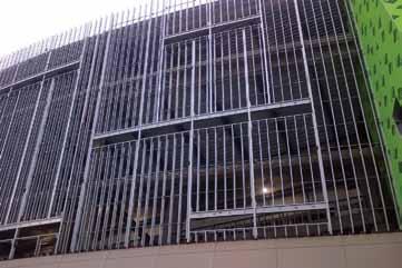
Figure 3. Staggered stick-framed openings at the west building elevation.
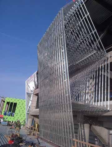
Figure 4. Installed CFS wall panel.
stick framed walls at the lower collar, the bypass connections to the super structure are made with vertical slide clip connections at all levels above the main concourse (Figure 2). The vertical slide clip (VSC) connections allow each level to deflect independently under gravity loading without any vertical load transfer to the attached framing. The large facility requires systems of an equal scale to meet its high electrical, mechanical and plumbing demands. To avoid possible conflicts with various systems’ piping and ductwork, BIM software was used during the design phase to coordinate CFS framing with the building systems and provide clash detection prior to installation. This extra measure enabled multiple disciplines to work together and provide solutions in the early stages of the project,
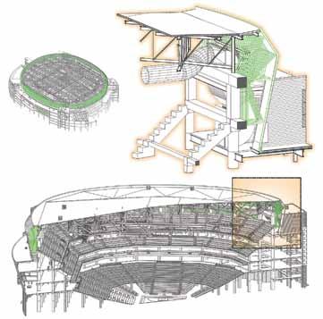
Figure 5. BIM rendering of Pinnacle Bank Arena upper seating bowl. Figure 6. “Jig Table” used for on-site panel construction.

preventing delays during the construction phase. One specific item discovered using BIM was interference between the space frames and a large ventilation duct in the upper seating bowl of the arena (Figure 5). This discovery resulted in the addition of structural steel during the design phase, to allow for CFS space frame attachment around the ducts, avoiding potential costly field modifications during construction. The unique and complex layout of the arena also had an impact on the construction methods used. The space frame wall panels were constructed on a “jig table” during the day, and lifted into place by crane in the evening. A concrete slab was poured on-site to create a jig table large enough to layout four panels at one time (Figure 6). Each panel was constructed of ten individual frames, which were tied together with cold rolled channel to create
Attention Bentley Users
Have you received your automatic quarterly invoice from Bentley? Would you like to reduce or eliminate these invoices? Use SofTrack to control and manage Calendar Hour usage of your Bentley SELECT Open Trust Licensing. Call us today, 866 372 8991 or visit us
www.softwaremetering.com
space frame wall panels. The panels were lifted by a crane via engineered pick points, clipped to the super structure and lapped on to previously installed vertical stud framing. A total of 96 space frame wall panels were required to complete the construction of the structure’s upper collar.
Conclusion
The ideal combination of construction materials, along with coordination of multiple disciplines, ensured the Pinnacle Bank Arena was successfully completed on time. The use of innovative design concepts and construction practices were valuable in addressing a challenging building design and keeping the project on schedule. The CFS framing was utilized to accommodate the ever-changing slopes of the exterior metal wall panels and the tri-radial curve of the building’s footprint. Its lightweight characteristic allowed contractors to more easily build and transport large CFS wall assemblies, lending favorably to wall panelization. As demonstrated during construction of the Pinnacle Bank Arena, specialized and complex panel framing can be constructed in a controlled environment, then lifted, and connected to the structure. Benefits of the panelized construction method include increased quality assurance, decreased production time, and overall project safety.
Innovative designs often require engineers and contractors to utilize building materials in new ways, reinforcing the importance of proper material selection. When selecting building construction materials, consideration should be given not only to achieving the desired building aesthetics, but also to project constructability.▪
Jeffrey Kreinke, P.E., S.E., is a project manager and structural engineer at Excel Engineering, Inc. in Fond du Lac, WI. He served as the principal cold formed steel engineer for the Pinnacle Bank Arena. He can be reached at jeff.k@excelengineer.com. Karl Scherzer, P.E., is a principal and structural engineer at Excel Engineering, Inc. in Fond du Lac, WI. He can be reached at karl.s@excelengineer.com. Jamie John, E.I.T., is a senior technician at Excel Engineering, Inc. in Fond du Lac, WI. She can be reached at jamie.j@excelengineer.com.
Project Team:
Owner: PC Sports Structural Engineer of Record: Buro
Happold Consulting Engineers PC Architect of Record: DLR Group Construction Manager: Mortenson
Construction
Specialty Structural EOR for CFS
Framing: Excel Engineering, Inc.
Wall Panel Fabricator/CFS
Framing Contractor: Falewitch
Construction Services, Inc.


