123 minute read
Advertiser Index
InFocus new trends, new techniques and current industry issues Toward a Bright Future By Barry Arnold, P.E., S.E., SECB
Jon Schmidt, and the past and present editorial board, did an excellent job of building STRUCTURE magazine into a high-quality, sought-after publication. Under Jon’s leadership and the talent and commitment of the editorial board, STRUCTURE magazine has become a widely-read and wellrespected publication. The profession owes Jon, those who served with him, and those who have contributed content to the magazine, our sincere appreciation. STRUCTURE magazine’s Vision Statement clearly defines the magazine’s destiny: STRUCTURE magazine will be the premier resource for practicing structural engineers. Its Mission Statement contains the road map of how the magazine will achieve its destiny: The Editorial Board will engage, enlighten, and empower structural engineers by publishing interesting, informative, and inspirational content in STRUCTURE magazine that is professionally relevant, technically reliable, and intellectually refreshing. To guide the Editorial Board in making decisions regarding magazine content, they adhere to the following, equally important, objectives: First, disseminate useful tips, tools, and techniques that will help structural engineers increase the quality, productivity, and profitability of their work; Second, introduce new and innovative concepts in structural engineering through project descriptions, case studies, lessons learned, and other approaches; and Third, promote structural engineering as a true profession, not merely a technical avocation, and highlight how it is unique from the other design disciplines. The Editorial Board, consisting of three members from ACEC/ CASE, three members from NCSEA, three members from ASCE/ SEI, and three members from industry, has done an excellent job of adhering to these objectives, mission, and vision. The Editorial Board’s work and contribution to the profession have been considerable and commendable. Having proven effective and valuable in the past, these are the objectives that the Editorial Board and I will continue following in pursuit of the magazines’ mission and vision. In addition to the types of articles you are familiar with, the editorial board will continue to seek out articles highlighting unique design approaches and imaginative solutions. STRUCTURE magazine should be a safe place to learn. It should be a place where questions can be asked and discussed freely, as well as a place where structural engineers can express innovative ideas and opinions and receive a respectful critique from their peers. STRUCTURE magazine must be a place where quality education and enlightenment are received without fear or embarrassment. It must be a place where structural engineers can look to re-stock their technical, business, and managerial toolboxes with relevant information. I may be the Editorial Chair, but I serve you and the profession. STRUCTURE magazine is your magazine. The members of the Editorial Board are open to your comments and suggestions, and we will eagerly review any content you submit. I want to provide a magazine you want to read. I want this to be a magazine you look forward to receiving and spending time reading, devouring the ideas it contains and discussing the design approaches presented during inner-office, lessons-learned type meetings. I want to use this medium to inspire structural engineers and instill a vision of what we can accomplish. I want the readers to be inspired to dream big and speak proudly about the profession. I want you to be encouraged to bravely stand up, stand out, and stand for something. My hope is that every structural engineer will be inspired by the articles they read, that they will embrace the people they read about as mentors and find value in the insights they share. I want every structural engineer to wear the title structural engineer proudly as a badge of honor, and be willing to defend it fiercely and fearlessly. I want you to believe in yourself as much as I believe in you. I want STRUCTURE magazine to remain surprising, novel, and interesting by including the work of thought leaders. I want you to see a future with abundant opportunity and ways to express your creative and technical skills and ability. Instead of worrying about changing the code every three years and complaining about having to obtain continuing education credits, we should worry that the value of being a structural engineer will plateau or decline. An engineer friend said that professional licenses were secure, and that the state would never take them away because they are a profitable revenue stream. Although his assessment and conclusion may be correct, it troubles me that, as a profession, we have missed the mark. If the only reason we are allowed to exist as a profession is because the states make money from licensing regulations, then somewhere along the way we have failed to adequately inform the public about the critical role we play in protecting their health, safety and welfare. Have the words professional and engineer become so over-used and so misused that they mean nothing? Have we spent so much time advocating structural engineering to structural engineers that our message hasn’t been heard by the public? Given all the accomplishments of the structural engineering profession, why, when the term engineer is mentioned, does the public only think of Howard Wolowitz? While I am serving you as Editorial Chair of STRUCTURE magazine, I want the Editorial Board to support NCSEA, CASE, and SEI as they take action to strengthen and improve the profession in meaningful ways, so that it will exist in grand splendor in the future.▪
Barry Arnold (barrya@arwengineers.com), is a Vice President at ARW Engineers in Ogden, Utah. He chairs the STRUCTURE magazine Editorial Board, is the Immediate Past President of NCSEA, and a member of the NCSEA Licensure Committee.
Structural DeSign
design issues for structural engineers
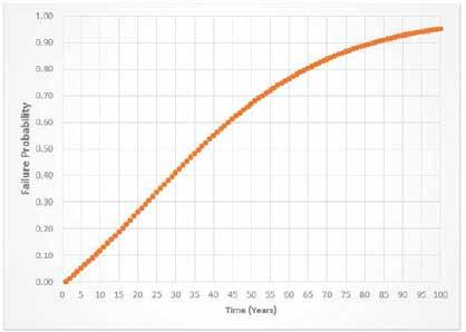
Historically, reinforced concrete has been thought of as very forgiving when it comes to the amount of time the material performs in service. Although there is a lot of truth to this, the environment inevitably can shorten reinforced concrete’s life expectancy, resulting in costly repairs and disruption to everyday life. When we think of durable concrete, the Pantheon in Rome comes to mind. This structure has been in service for well over 2000 years. If Roman concrete can last for centuries, surely current construction materials should be suitable to serve a 50 or 100 year design life. In some ways, assumptions on material durability may have influenced early specifications which fail to address material performance over time. As our understanding of durability increases, we expect increased performance of the materials we put into service. In the instance of landmarks or monuments, we want to build and preserve these structures in perpetuity. As we are constantly striving Durability of Reinforced Concrete to improve material performance, we simultaneously want to be more sustainable in our approach, and be proud of what we build. Like Roman engineering, attaining durable structures By Paul Noyce and Gina Crevello with an extended service life, like the Pantheon, should be our end goal. A vast amount of research was carried out on the durability of concrete from the 1970s to the 1990s and a great deal of technical knowledge was achieved. It is now possible to utilize this information in our designs to provide a level of confidence to owners on the future performance of reinforced concrete structures. To make reinforced concrete more durable, Paul Noyce is a concrete and a design approach has to be considered; the material durability expert. Paul is the Chairman of National Association of Corrosion Engineer’s (NACE) Standard Technical Group 01 for Reinforced Concrete. He may be reached at pnoyce@e2chem.com. Gina Crevello is material conservator. Gina is on the board of the Association for Preservation Technology International. She may be reached at gcrevello@e2chem.com. performance over time should be modeled where various dimensions and material specifications can be reviewed. This type of design is referred to as service life design (SLD), where the engineer can demonstrate performance of the selected structure over time, as seen in Figure 1. The SLD has to demonstrate the performance and degradation of the engineering materials. Both of these are heavily influenced by the environment which, in turn, is affected by local macro and micro climates. In addition to understanding the environment, knowledge of local materials is required, as this too varies greatly. Because of these variations, material performance and service life should be treated stochastically.
Performance and Degradation
The performance of a structure is typically seen as how well it is functioning related to its use. This can be further expressed as the performance of key principles like load capacity, stability, safety and visual appearance. Performance is regarded by many as a quantifiable property and is always a function of time. When considering time in evaluating performance, degradation of the structural materials is regarded as the most important factor. This links the structure’s performance directly with the durability of its materials. ASTM E632, Standard Practice for Developing Accelerated Tests to Air Prediction of the Service Life of Building Components and Materials, defines durability as the capability of maintaining the serviceability of a product, component, assembly, or construction over a specified time. Serviceability is viewed as the capacity of the above to perform the function(s) for which they are designed and constructed. Degradation is the reduction or decrease in performance over time and can be understood
as the inverse of performance; therefore, measuring degradation allows one to assess performance related problems. Performance is then measured by a minimum acceptable level, while degradation is set by a maximum acceptable level. These levels are known as durability limit states and can be defined for future performance measurements. The limit state can be set to either an ultimate or serviceability limit, which defines the service life and ultimately the performance requirements of the structure. When looking at degradation problems in reinforced concrete, the two main materials, the concrete and the reinforcing steel, are what impact the durability of the structure. The symbiotic relationship between reinforced concrete and steel ensures that, if defects exist within the original design or material selection and if load factors that enhance corrosion are present, deterioration will ensue. In turn, the environment in which these materials are installed impacts and defines their long term performance and degradation.
Service Life
Service life of materials can be assessed by their expected lifetime, or their acceptable period of use in service. As service life can be expressed in three ways, technical, functional or economic, then different use requirements are needed. In assessing service life as a business policy, financial tools and mathematical calculations can be carried out to develop a maintainability and reliability analysis. The questions regarding service life and maintenance are always related as maintenance routines are carried out during the service life of the structure. Maintenance activities, which influence service life, need due consideration. This changes the overall definition of service life which is stated as “when routinely maintained” as defined in TC 71-PSL Systematic Methodology for Service Life: Prediction of Building Materials and Components (Masters and Brandt, 1989). It is always the requirement of the owner to define the service life requirements and set forth the duration requirements, which sets the target service life.
Probability of Failure
When a target service life is set, a stochastic durability design will involve a definition of the maximum probability of not reaching a certain limit state. These limit states can be either an ultimate limit state (ULS) or a serviceability limit state (SLS). Two distinct types of failure exist, as either a durability failure or mechanical failure. However, in most instances, a material durability failure will be responsible for the mechanical failure. A maximum failure probability has to be set and defined by evaluating the consequences of the risk of failure. The risk is defined as the multiplication of the probability of failure by the amount of damage (Kraker, de Tichler and Vrouwenvelder, 1982). When considering how to set the required probability of failure, social, economic and environmental criteria should be considered. For social criteria, the importance of the structure and the consequences of failure, where human lives are at risk, is essential. Economic criteria should consider the financial consequences of disruption due to failure when these are considerably more than the construction cost. As with environmental and ecological criteria, consideration is due to either an environmental disaster or in line with ecological principles. Probability of failure can be applied during the design phase of new structures or to existing structures, as the principles are the same. The only significant difference is that the margin of safety used for existing structures will be much lower than new construction. continued on next page
ADVERTISEMENT–For Advertiser Information, visit www.STRUCTUREmag.org

Conceptually, a durability design is based around safety, where the structure must resist failure by various hazards it is exposed too. Safety has typically been applied to structural mechanics; however, we should not be so restricted in our design when dealing with the performance of materials. The use of this technique is increasingly advocated for dealing with durability and service life problems (Siemes, Vrouwenvelder and van den Beukel, 1985). By incorporating time into the design, we can now value the degradation of the materials as part of the overall problem. This time-based design has to set performance related requirements to ensure that the structure fulfils its long term service life goals for safety. This then has the effect of forcing the designer to ensure that the material selection will achieve the long-term durability requirement for the service life goals.
Category Class Condition
Freezing and Thawing (F) F0 Concrete not exposed to freezing-and-thawing cycles F1 Concrete exposed to freezing-and-thawing cycles with limited exposure to water F2 Concrete exposed to freezing-and-thawing cycles with frequent exposure to water F3 Concrete exposed to freezing-and-thawing cycles with frequent exposure to water and exposure to deicing chemicals Water-soluble sulfate (SO4 2-) in soil,
percent by mass[1]
Dissolved sulfate (SO4 2-) in water, ppm[2]
Sulfate (S) S0 SO4 2- < 0.10
S1 0.10 < SO4 2- < 0.20 SO4 2- < 150
150 < SO4 2- < 1500 or seawater
S2 0.20 < SO4 2- < 2.00 1500 < SO4 2- < 10,000
S3 SO4 2- > 2.00 SO4 2- < 10,000
The Environment
When considering a durability design, a key understanding of the environment and the exposure of the materials is essential in In Contact with Water (W) W0 W1 Concrete dry in service Concrete in contact with water and low permeability is not required Concrete in contact with water and low permeability is required achieving a good design. The building code requirements for structural concrete, the C0 Concrete dry or protected from moistureAmerican Concrete Institute’s ACI 318-14, defines exposure categories and classes as shown in Table 1. BS EN 206:2013: Concrete Specification, Performance, Production and Corrosion Protection of Reinforcement C1 Concrete exposed to moisture but not to an external source of chlorides Conformity, also provides exposure classes (C) Concrete exposed to moisture and an external source of for concrete durability, as shown in Table 2. C2 chlorides from deicing chemicals, salt, brackish water, seawater, Although both these tables differ overall, or spray from these sources it can be seen that they both consider the 1 Percent sulfate by mass in soil shall be determined by ASTM C1580. degradation of the materials. ACI categories 2 Concentration of dissolved sulfates in water, in ppm, shall be determined by ASTM D512 or ASTM D4130. are broken down by a damage mechanism and then class, with a variation of severity. As with BS EN 206:2013, the class is broken down based on wet and dry cycles, with various corrosion risks associated with a letter in the exposure class. As with most situations, a series of environments and contaminants can coexist on the same structure, so the design engineer must pay attention to this in the durability design. This can be extremely
NEW
engineering manual
STEEL DECK INSTITUTE s ®
DIAPHRAGM DESIGN
EDITION 4
STEEL DECK INSTITUTE s ®
The Fourth Edition of the SDI Diaphragm Design Manual (DDM04) complies with the requirements of the new ANSI/AISI S310-2013 North American Standard for the Design of Profi led Steel Diaphragm Panels. It includes new and expanded design examples and diaphragm strength tables.
NOW AVAILABLE
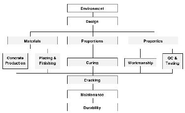
Figure 2. Holistic approach to durability. Courtesy of NRMCA.
X0 For concrete without reinforcement or embedded metal where there is no significant freeze/thaw, abrasion or chemical attack No risk of corrosion or attack
XC1 Dry or permanently wet XC2 Wet, rarely dry XC3/4 Moderate humidity or cyclic wet and dry XD1 Moderate humidity
Corrosion induced by carbonation
Corrosion induced by chlorides XD2 Wet, rarely dry other than from seawater XD3 Cyclic wet and dry XS1 XS1 Exposed to airborne salt but not in direct contact with sea water Corrosion induced by chlorides XS2 Permanently submerged from seawater XS3 Tidal, splash and spray zones XF1 Moderate water saturation without de-icing agent Freeze/thaw with or without XF2 Moderate water saturation with de-icing agent de-icing agents XF3 High water saturation without de-icing agent XF4 High water saturation with de-icing agent or sea water Chemical attack (ACEC classes) Refer to BS 8500–1 and Special Digest 111
complex on some structures but, if overlooked, can result in a degradation failure in an unacceptable period, which can cost many millions of dollars. As we repair structures today, durability and the environment are not considered enough in their role in leading to premature and costly maintenance repairs. The most deleterious durability failure of concrete is related to corrosion of the embedded reinforcing steel, which subsequently causes damage to the surrounding concrete and results in millions of dollars in damage, repair and associated ‘indirect’ costs.
Summary
In summary, it is essential that a holistic approach is used for the design of durable concrete structures by considering multi-faceted aspects of the structure, the structure’s relationship to its surroundings, appropriate material selection, the utilization of proper construction methods, adequate quality control and planned maintenance. Figure 2 provides an overall holistic approach to the considerations required to provide durable concrete structures. As we can see from Figure 2, the overall approach to durability goes beyond the design engineer’s work. By reducing QA on a construction project due to cost and budget constraints, the long term performance of a building or a structure can be drastically affected. QA is still, in our opinion, one of the major factors in achieving long term durability of concrete structures. Whether designing new or fixing existing, attention to the installation of the work is paramount to the structure’s long term survival in our ever changing environment.▪
Design Aids and Solutions.
Analysis, design, done.
Use promo code DESIGN-15 and save 15% on our popular design guides at www.crsi-webstore.org.
24/7 continuing education and FREE technical and informational downloads at www.crsi.org!
Structural rehabilitation
renovation and restoration of existing structures
Figure 1.
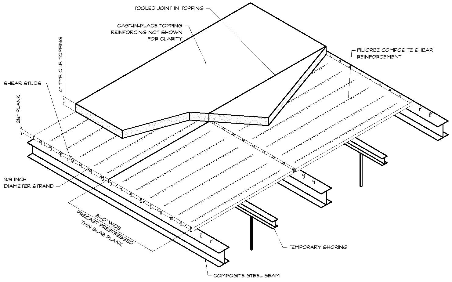
Precast, Prestressed Thin Slabs in Parking R ecently, Pennoni Associates was involved in the investigation and Garage Structures assessment of several existing parking garages constructed with precast, prestressed thin slabs. In this type of structural system, Or, When Thin is a Not precast planks function as stay-in-place formwork a Win-Win and become a part of an overall composite slab once a field-cast topping is placed and the shoring is removed. Although this type of construction is By D. Matthew Stuart, P.E., S.E., P.Eng., F.ASCE, F.SEI, SECB common in bridge decks, it is more unusual in parking garages, except perhaps in the Delaware Valley and surrounding region. In those areas, it is popular in cast-in-place concrete building construction as a voided system and is referred to as D. Matthew Stuart Wideslabs. There appear to be no similar precast, (MStuart@Pennoni.com) is prestressed thin slab products available for comthe Structural Division Manager mercial use in the remainder of U.S. at Pennoni Associates Inc. in Philadelphia, Pennsylvania. The System The cross-section of the thin composite slab typically consists of a 2¼-inch-thick by 8-footwide solid precast, prestressed concrete planks in combination with a minimum 4-inch-thick castin-place concrete topping. The system is capable of clear spans of roughly 20 feet between beams that act compositely with the topping – either structural steel (Figure 1) or precast U-shaped beams that are infilled when the field-cast concrete is placed (Figure 2). The erection of the planks and beams requires the use of temporary shoring that remains in place until the field-cast topping is placed and has achieved adequate compressive strength. The composite capabilities of the combined precast planks and cast-in-pace topping is provided primarily via vertical lattice or “filigree” reinforcing that is cast into the precast planks but protrudes above the top of them in order to engage the topping. The primary positive or bottom flexural reinforcing of the resulting system is provided by the prestressing strands (typically 3/8-inch diameter) in the precast planks, while the top or negative flexural reinforcing is provided via conventional deformed bars in the topping. Temperature and shrinkage reinforcing is also provided transverse to the slab span in both the precast planks and the cast-in-place topping. Unlike similar thin precast components used in parking garage construction, such as double tee flanges, mechanical plank edge connections (e.g., embedded plate weldments) are not employed along the abutting joints of adjacent planks. As a result, the nominal transverse reinforcing in the topping and aggregate interlock of the cast-inplace concrete are the only mechanisms available for transferring moving, concentrated vehicular wheel loads across the open joints below, as well as the tooled joints in the topping that generally align with the plank joints. A search of the available literature indicated that the structural capability of this portion of the thin slab system to function properly in a parking garage appears to be untested.
The Problem
Similar to an aged and failed, tooled and sealed topping joint in a typical double tee parking garage structure, joints in a thin slab garage structure will allow for moisture intrusion into the joint. The moisture, which is typically contaminated with chlorides from deicing salts either applied to the surface or brought in from the road by vehicles, tends to migrate through the
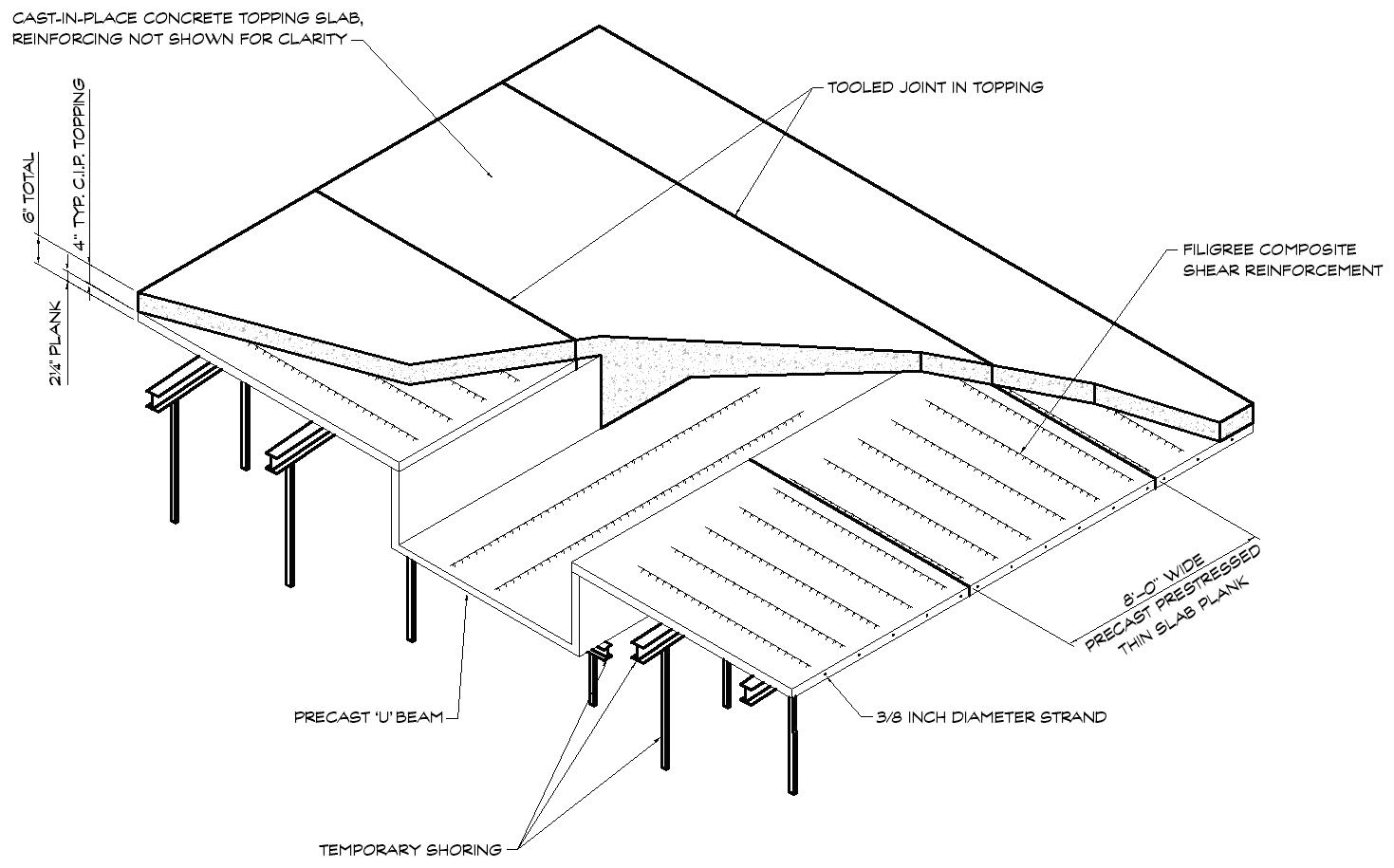
Figure 2.
joint. The moisture flows horizontally into the interface between the topping and precast via capillary action, and across the bottom surface of the soffit of the precast (Figure 3). As a result, any reinforcing steel that is adjacent to the joint will begin to corrode, causing the surrounding concrete to deteriorate. In a double tee flange edge, this can result in isolated damage to the connectors and mesh reinforcing, which can often be repaired conventionally. In a thin slab plank, however, the proximity of the outside strand to the joint edge can result in the corrosion of a portion of the primary positive flexural reinforcing in the composite slab system. If the two outside strands of a typical 6-strand plank become corroded to a point at which a considerable amount of cross-sectional area is lost, or the strand is completely consumed – which is frequently the case because of the relatively small diameter of the strand (Figure 4) – the associated 8-foot-wide section loses 33% of its positive moment capacity. This vulnerability of the thin slab system is exacerbated by the lack of an adequate vertical load transfer mechanism at the joints. This susceptibility was evident even in garages that were only 5 to 10 years of age in which the condition of the tooled topping joint sealant appeared to be in very good condition. Test results indicated that the same level of contamination existed at both the driving surface above and the plank soffit joint edge below, with water-soluble chloride content as high as 2.63% by mass of cement versus an ACIrecommended limit of 0.06% for prestressed members. Similar planks in bridge decks do not appear to exhibit this phenomenon, primarily because tooled and sealed joints in the topping are not routinely used in such construction. Petrographic testing of thin slab planks revealed additional susceptibilities of the product, including the lack of sufficient airentrainment and concrete cover beneath the strands that was less than the 1-inch minimum recommended by ACI for precast slabs. In addition, laboratory testing revealed significant coarse aggregate segregation due to high-slump concrete and/or over-vibration, as well as carbonation as deep as 1 inch from the bottom of the soffit.
The Solution for Older Garages
The inability of individual deteriorated planks with completely corroded strands to share the support of imposed vertical loads with adjacent intact planks, due to the lack of mechanical connections at the thin slab joints, caused concern for the structural integrity of these planks. Furthermore, it was also not unusual for adjacent strands in adjoining planks to be corroded as well. This led to the development of the following mitigation strategy for the unsafe conditions created in garages, that were approximately 30 years of age, by the loss of one or more strands out of the available six in each plank. Based on the age of these older garages, the original design live load was probably 50 psf. Comparing this with the current minimum garage live load of 40 psf suggested a reserve capacity of 10 psf, or 20% of the assumed original live load capacity of the planks. A loss of only one out of six strands equated to a strength reduction of approximately 17%, which was less than the 20% reserve capacity. Therefore, planks that had only lost one strand were deemed to be still capable of safely supporting the minimum imposed live load. continued on next page
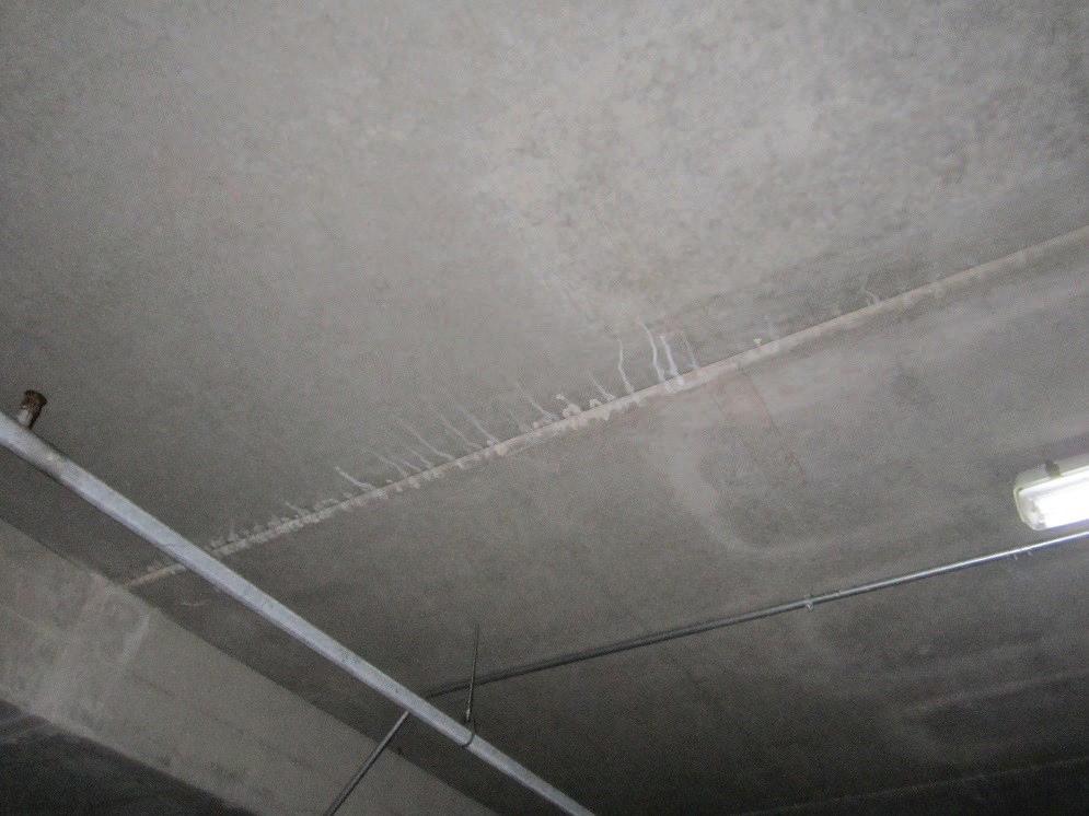
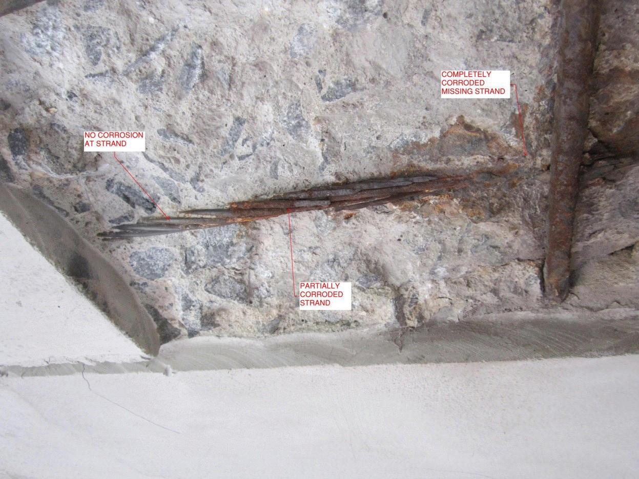
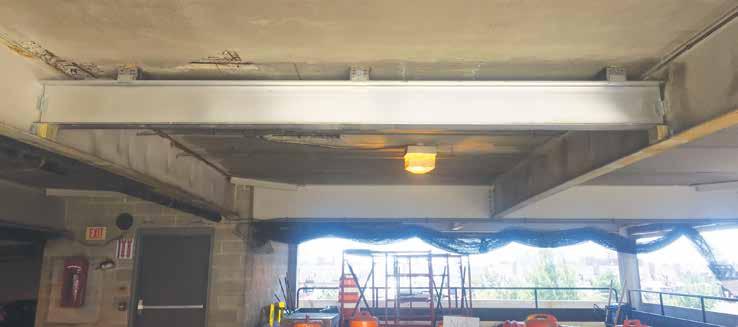
Figure 5.
The loss of two out of six strands, which was the maximum strand loss documented in any of the 30-year-old planks, equated to a strength reduction of approximately 33%, which was greater than the 20% reserve capacity. These planks required the installation of aluminum shoring beams immediately below the location of the corroded strand, which were shimmed tight to the underside of the plank soffit. The shoring beams spanned between, and were supported by, the existing steel beams that provided the original support of the planks (Figure 5). The composite nature of the plank and topping, made possible by the vertical lattice shear reinforcing, also makes it difficult to facilitate conventional repairs to both the precast and cast-in-place components of the slab system. This is because the vertical shear reinforcing is not robust enough to avoid being significantly damaged when subjected to the renovation demolition of the surrounding concrete. Supplanting the existing shear reinforcement with alternate means of providing composite action was also not considered practical or economical. As a result, any repairs from the top surface or bottom soffit that encountered the shear reinforcement would cause a loss of composite action between the planks and topping. This condition meant that practical options for conventional concrete repair were extremely limited. Additional challenges in the older garages included the absence of a chloride extraction or re-alkalization system that would not risk hydrogen embrittlement of the strands, insufficient concrete cover over the reinforcing, and non-uniform air-entrainment and the resulting susceptibility of the concrete to freeze-thaw damage. Because of these impediments, the most practical and cost-effective method of renovating the older garages involved the complete demolition, removal, and replacement of the existing composite slab system. A review of several options led to the selection of a 3¼-inch-thick cast-in-place slab on top of a shored 3-inch-deep composite metal deck, for a total thickness that matched the original slab system.
The Solution for Newer Garages
The mitigation strategy for the newer garages, where the extent of chloride contamination and carbonation had not yet resulted in corrosion of the plank strands, was different. Due to the limited ability of the filigree vertical lattice reinforcing to withstand renovation demolition of the CIP topping and the difficulty of replacing it with an alternate method of ensuring composite action between the prestressed planks and the topping, the success of repairs to the surface delaminations was difficult to predict. This led to the recommendation to conduct a limited test program at one of the deteriorated surface areas in order to assess the potential for successful repair. In order to prevent further moisture intrusion at the plank joints and the subsequent introduction of road salts, the top wearing surface would be coated with a waterproofing membrane after such repair. The presence of significant chloride contamination of the plank soffits at the joint edges, even with the elimination of further chloride-contaminated moisture migration due to the presence of a new surface membrane, would result in the eventual corrosion of the affected strands. This potential existed because of the exposure of the concrete to ambient conditions, which would allow for enough humidity in the concrete to be present to enable corrosion cells to develop. The recommended solution was installation of a surface-applied, metalized cathodic protection system on the plank soffit at the area of chloride contamination. The recommended proprietary system was capable of providing long-term galvanic protection without damaging the prestressing steel via hydrogen embrittlement. The location and extent of the metalized cathodic system was established based on the results of an Electrical Resistivity survey. This allowed for the extent of the potential for corrosion to be mapped in areas not immediately adjacent to the plank joints, to ensure that the protection system did not have to be installed over the entire soffit.
Conclusion
The results of the investigation revealed the susceptibility of precast, prestressed thin slab parking structures to corrosion and resulting loss of strength over the life of this type of construction. It is interesting to note that the International Parking Institute began discouraging the use of this type of product in parking garages in 2004. In addition, a number of reputable consulting engineering firms that specialize in the design of parking structures do not recommend the use of precast, prestressed thin slab members in garages.▪
Technology
information and updates on the impact of technology on structural engineering
Tilt-Up and BIM
The Value Proposition
By Douglas G. Fitzpatrick, P.E. and Joe Steinbicker, P.E., S.E.
Douglas G. Fitzpatrick is President of Fitzpatrick Engineering Group in Cornelius, NC and is an avid BIM advocate. He can be reached at dfitzpatrick@fegstructural.com. Joe Steinbicker is a charter member and past chairman of ACI Committee 551, Tilt-Up Concrete Construction. He is also a founding member of the Tilt-Up Concrete Association and past member of their Board of Directors. He recently co-authored the book, Engineering Tilt-Up. He can be reached at joes@tilt-werks.com. I remember my first day of work as a young engineer like it was yesterday. The firm where I was starting my career was ceremoniously ditching the teletype machine that had provided them with computing power from a timeshared computer in a remote office building, in downtown Charlotte, NC, in favor of a desktop computer – a Wang SVP. It sported 32,000 characters of user memory (yes, characters – this was before MB and GB), a 500,000 character 8-inch diskette drive, and a 4 million character Winchester fixed disk drive. Some of you may have had one of these in your office. The ability to run our little programs from the main frame computer downtown via the teletype punch tape reader had been a significant improvement over hand calculations, although each time you hit the run button there was a charge. “Garbage in = garbage out” had a price tag to it back then. While our new Wang had a not so insignificant price tag, we quickly discovered it gave us much more computing power than we could have imagined and many more opportunities to experiment with programming and our designs. It didn’t take very long before we needed more computing power. We were really seeing benefits of local accessibility of the computer in the office but, more importantly, we were saving a significant amount of time. The computer had easily replaced hand number crunching with the enviable benefit of knowing if the programming was right, the answers would be right – every time – eliminating human error. The mundane repetitive calculations we were doing by hand could be automated and free us to focus other things. Of course, the rest is history. Computing power has grown by leaps and bounds. The sophistication of our analysis and design software has allowed us to economically analyze buildings that would have been unthinkable when I first graduated. The engineering community has been a significant beneficiary of what technology and computing power has to offer. And now, we have BIM – a way to virtually construct a building before anyone lifts a hammer. Architectural and engineering disciplines can perform an electronic mash-up of their work before handing it off to the construction team. For the first time, they have an opportunity to know that all of their systems work and play together well. Similarly, our construction partners have all seen significant improvements due to technology as well. Construction simulations, electronic tracking of materials at a job site, even laser scanning of existing conditions are common technologies at many of today’s construction sites.
But Some Things Have Not Changed
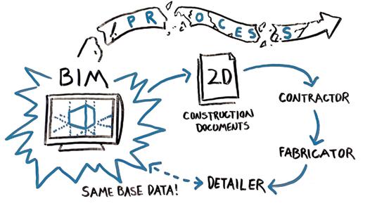
Sadly, though, that’s where the significant technological improvements end. The way we get from design intent to construction has remained essentially unchanged since that first day as a young engineer (Figure 1). Our use of all of this wonderful 3D rich content dies with a hand-off of 2D paper drawings for construction. Both sides of the equation benefit greatly from technology individually, but the missing link – the gap between our two processes – is hindering the true efficiency improvements technology could really bring to bear on our projects. In 2004, I left my old firm and started out on my own. We adopted BIM in 2006 and quickly recognized its potential. As my new firm expanded our use of BIM, this gap between design and construction became more apparent.
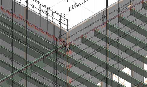
Figure 2. Complete steel and tilt BIM combined together for visual coordination.
We do our work in BIM and hand off our design via 2D drawings, only to learn later that the contractor has recreated most of the original design models himself. Schedules are generally a driving factor in most of our projects. It seems like everyone needs to get into their building quickly and the current economy has only escalated the need. One of the ways the construction industry has responded is by involving construction trade partners earlier. Identify the tasks on the critical path and get those players involved earlier. On most of our projects, that usually means getting the steel fabricator involved at some point during the design phase. While I think we could agree that schedules have improved, it has been accomplished by taking an old, out dated process and simply making it faster, not more effi cient. Th is is apparent by the increasing amount of RFIs and change orders we engineers have to deal with. Earlier involvement means our drawings are less developed, which translates into lots of clarifi cations. On our projects, early involvement typically means the fabricator is hired based on a GMP before the design is fi nished which has consistently resulted in change orders. Th e constant parade of change orders for our steel buildings is not good for the industry, regardless of whether they’re justifi ed or not. Owners won’t tolerate having to pony up for more cost forever when they think they have been given a GMP.
The Process Needs to Change
In 2012, we set out to change the old outdated process. We fi gured out a way to share our structural data, multiple times during the design phase of the project, with a steel detailing partner to shorten the delivery of steel to our projects by 8 weeks. And, we eliminated the RFIs and change orders in the process by creating the steel fabrication package during design. Problem solved, with case studies to demonstrate the savings. Th e key factor here was leveraging our structural data and sharing it downstream. We could use it both to improve our productivity from analysis to construction documents; and also make downstream processes more effi cient, not just faster, by eliminating the recreation of data. Once we saw the benefi t this new process brought to the construction of our steel buildings, we started looking for other building types that could leverage what we had learned from steel. Our tilt-up projects seemed to be handicapped by many of the same problems. Our analysis is done in 3D, yet the method of communicating our design is 2D. Someone else is typically responsible for coordinating the minutia of details, completing the engineer’s design intent and delivering it to the fi eld in the form of shop drawings. And, much like our steel buildings, all of the construction phase work involves the recreation of data the engineer already has, and is subject to the same RFI and change order hazards.
Leveraging Lessons Learned
In 2014, we started looking for tilt-up design software that would address the following criteria and allow us to really take advantage of BIM: • Working with walls as opposed to individual panels to minimize the bookkeeping while the design was changing, i.e., four walls instead of 100 individual panels • Adding loads globally to walls and the program divides the loads to individual panels
SIGN UP FOR A FREE TRIAL TODAY
TILT-WERKS.COM Tilt-Werks is a Unique & Powerful New Technology
• Developed specifically for the tilt-up industry • Web based — Can be accessed anywhere, anytime Tilt-Werks Automatically Generates:
• Structural design for all walls/panels • Panel design/shop drawings • Panel reinforcing design & placing drawings • Complete panel reinforcing cut list • Material quantities & cost estimates • Dayton Superior product parts list & pricing • Building Information
Models (BIM)
• Adding panel geometry, openings and embeds • Associativity of components – move a support line, and loads and embeds move with it • Automated determination and design of the panel • Automated generation of panel layout drawings and reinforcing drawings • A BIM ready 3D output of the walls – an IFC complete with panel joints and openings • Quantity take-offs that we could share with downstream users. Tilt-Werks® satisfied all of those criteria. So, what can you do with all of this design information to add value to your tilt-up projects with BIM? With some careful planning of modeling and origins, the BIM you get from your steel design program can be attached to the IFC model you get from the tilt-up software. The automated panel layout shop drawings from the tilt-up software – complete with embeds and openings – could be repurposed by attaching each drawing to the inside face of the wall IFC model at its respective panel location. That puts the steel framing, panels, openings and embeds all in the same context. As the design evolves, the steel BIM gets updated from the analysis program, and the exported IFC and panel drawings are refreshed from the tilt-up software. You could end up with something like Figure 2 (page 19). But Doug, you say, this looks like all the other images found on any company’s website on the internet. Where’s the value in another pretty picture? Not only that, this looks really tough to review and coordinate in 3D.
Leveraging BIM
So, let BIM do all the work! By cutting sections at the face of the walls, coordination becomes very easy. The steel and tilt-up elements are all shown in context to one another and errors can be easily uncovered. If you set your view attributes correctly, you can see which members are on the near side of the wall (solid) and which are on the far side (dashed). If you develop an embed naming convention that distinguishes between embeds on the upcast and downcast faces of the panel, you can visually verify that the embed labeling matches the location of the steel members – before the panels get built. In our case, we use an asterisk to identify embeds on the downcast face. For coordination, we scan the extracted elevations (Figure 3) to make sure all embeds with an asterisk
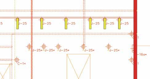
Figure 3. Using BIM to verify embeds and framing in complicated areas.
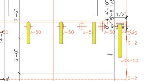
Figure 4. Using BIM to resolve coordination errors for tilt-up construction.
have a dashed member at their location. If a solid member is found, one of the two is wrong and the correction can be made. Figure 3 is an example of a section cut with framing on both sides of the wall. This composite BIM can also be used to check for errors as well, not just the upcast or downcast location of embeds. Because there are two analysis programs (steel and tilt-up), it’s not unthinkable that a change in one program doesn’t get picked up in the other, particularly while the design is changing. BIM is a perfect environment to do this error checking (Figure 4). This is an example where a new bay was added, the steel framing was modified but the tilt-up embeds had not been adjusted accordingly. So, BIM can do a really great job of coordinating our steel design and tilt-up design. But, what if we take this a step further to add even more value? What if the quantity take-offs from the tilt-up software were shared with the tilt-up sub-contractor? If the take-offs are robust enough and include all of the items that the contractor needs to price the project – length of forming, gross and net square footage of the panels, length and size of reveals, quantities of embeds, tonnage of reinforcing, etc. – they could all be used at any point during the design to help monitor the cost of the structure. What contractor or owner doesn’t want to know where they stand during the design phases instead of waiting until the design is finished? At any point during the design you can provide a take-off that could easily have dollar amounts applied to it.
The Value Proposition
Some of this may seem like a lot of extra work; some of it may not. The first time or two will require some trial and error as you home in on a system that works for your office. But once set up, updating is almost automated. You are getting design information from your steel design program pushed down to your
steel BIM multiple times during design, and as the tilt-up design continues to mature you can generate updated drawings, an IFC and quantity take-offs at any time. Here’s a summary at some of the key valueadd you gain by doing this extra work: • Single source responsibility for the design and detailing. You are the EOR for the project. Your seal is on the building drawings. Who best knows how the building needs to go together.
Why not leverage that knowledge and put it to good use. Do the coordination yourself and know you have everything covered. You have to review the shop drawings anyway. • Better coordination. If you have worked in BIM (3D) before, surely you have discovered something you wouldn’t have caught in 2D until the project was in construction.
Why wait for something to get caught later, regardless of who is
“responsible”, and have to deal with the RFI (or change order) in panic mode during construction.
Coordinate early, save time later.
Leverage BIM to help with all of that work. • Speed to market. If your tilt-up design program is able to generate the panel layout and reinforcing drawings automatically, you can easily generate a complete set of field use drawings when you issue your construction documents.
Think of the time savings you can offer your client by shortening the typical construction schedule. • Quantity take-offs. If your tilt-up software gives you robust quantities (surface areas, embeds, weights, tonnages, reveals, etc.) at any time during design, allow that information to be used downstream.
This can be particularly helpful if you are working with a design/build or fast-tracked project. Everyone has their finger on the pulse of the project cost these days. Anything you could do to help with that would be valuable. lesser fee than you. Even though you know you do a better job than those other guys, trying to sell subjective benefits to a client (“better” engineering, faster response time to questions, always accessible, and just plain nice guys) is difficult at best and generally a waste of time. However, if you can show you can add real value to a project – specifically time and/ or money – now you have their attention. A difference in design fees could pale in comparison to the additional revenue an owner receives by getting in their building
The Bigger Picture
I think we could all agree that the last seven years have been pretty tough on both the design and construction communities. Design fees are under constant pressure and it seems there is always someone willing to take a project for a a month early. Leveraging BIM on your tilt-up projects is a great place to start for adding tangible value your clients will notice immediately. By the way, if you’re doing what everyone else is doing, you’ll get paid what everyone else is getting paid. Find something your firm does better than everyone else, leverage it to the max to differentiate your firm from the rest and figure out how to translate it into real value for your clients. Hopefully, the thoughts presented here give you a decent starting place for your tilt-up projects.▪



This article is a two part series which discusses special inspection provisions for wood construction in the 2015 International Building Code (Part 1) and perspectives from several States (based on the 2012 International Building Code) on suggested handling of special inspections regionally (Part 2).
Special inspection is not a new term to the building code. The International Conference of Building Officials’ (ICBO) Uniform Building Code (UBC) has had special inspection requirements in the code since the 1961 edition. The Building Officials and Code Administrators’ (BOCA) National Building Code first introduced special inspection provisions in 1988. The ICBO and BOCA codes had a slightly different philosophy and emphasis, which resulted in very different special inspection implementation approaches in ICBO jurisdictions from BOCA jurisdictions. When the International Code Council’s (ICC) International Building Code (IBC) was first issued in 2000, it merged the ICBO and BOCA special inspection requirements into its Chapter 17. Today, the IBC continues this practice with criteria included in 2015 IBC Chapter 17, titled Structural Tests and Special Inspections. The Special Inspections in Chapter 17 are in addition to the inspections identified in Chapter 1 Section 110 and although Chapter 1 will not be covered in this article, Section 110.3.4 Frame Inspection is specific to wood construction elements.
Background
Special inspection is a quality control measure intended to ensure that certain critical – mostly structural – features incorporated into a structure are constructed properly. This requires inspection by professionals (usually registered design professionals) with specialized skills and experience to verify that the material and workmanship comply with approved plans, specifications, and industry standards. Some aspects of construction may only need periodic inspection, while other aspects of construction require continuous inspection. In Codes and most cases, wood construction is only required to have periodic inspections. The authority to standards enforce provisions contained in the building code for special inspections rests solely with the local building official. Since a building official certainly cannot be expected to be an expert on all technical updates and discussions related to codes and standards building systems contained in a modern structure, inspectors are necessary who have special expertise to evaluate critical building components. The purpose of special inspections is to provide additional evaluation and inspections above and beyond inspections which are normally performed by the building department, particularity in areas of construction where strength, safety, and construction practices have been determined by the building code, registered design professional, or building official to be sufficiently critical to warrant a special inspector. Ensuring competence of the special inspector has always been and continues to be Special Inspections for Wood Construction – Part 1 the responsibility of the building official. The registered design professional in responsible charge and engineer of record involved in the By David P. Tyree, P.E., C.B.O., design of the project are permitted to act as the James B. Smith, P.E. and Michelle approved agency, and their personnel are permit- Kam-Biron P.E, S.E., SECB ted to act as the special inspector for the work designed by them, provided those personnel are qualified to perform the inspection and are approved by the building official.
Pre-fabricated Wood Members
The definition of a pre-fabricated item is located in Section 202 of the IBC. The definition notes that any item that is manufactured in accordance David P. Tyree is the Central Regional Manager, James B. Smith is the Midwest Regional Manager, and Michelle KamBiron is the Director of Education at the American Wood Council, Washington, DC.
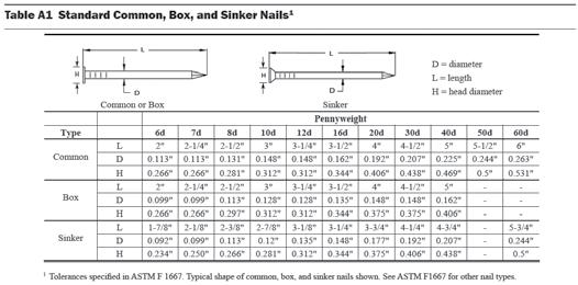
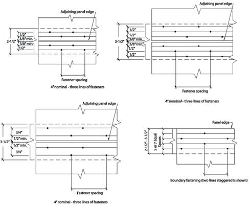
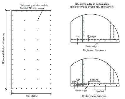
Figure 2. Special design provisions for wind and seismic – high load diaphragm nailing details.
with one of the standards referenced in the code (Chapter 35) is not to be considered a fabricated item and thus is not subject to the special inspection requirements of Section 1704. However, this exception is only permitted if the fabricator maintains approved detailed fabrication and quality control procedures that provide a basis for control of the workmanship and the fabricator’s ability to conform to approved construction documents and the code. As an example, most metal plate connected wood trusses, glued laminated timbers (glulam), and I-joists are manufactured to a referenced standard (such as ANSI A190.1 for glulam). Therefore, unless there is an unusual situation where a reference standard is not being used, special inspection of these items is not required by the IBC. Chapter 23 of the IBC specifies requirements for wood design and construction. Section 2303 specifies the minimum standards and quality control procedures for various wood products. Quality control certification programs such as those implemented by APA–The Engineered Wood Association, Truss Plate Institute, International Accreditation Service (IAS), etc., are covered under provisions specified in IBC Section 1704.2.5.1 for “fabricator approval.” These requirements include a comprehensive audit to stringent industry-specific performance criteria by trained auditors and industry professionals. IBC Section 1704 outlines requirements for special inspections and tests, contractor responsibility and structural observation. Since the 2000 IBC was published, this section of the code has changed several times and provides much more guidance for the building official.
Special Inspection and Tests
Where application is made to the building official for construction as specified in Section 105, the owner or the owner’s authorized agent, other than the contractor, shall employ one or more approved agencies to provide special inspections and tests during construction on the types of work listed under Section 1705. Per Section 1704.2, there are exceptions as to where special inspections are required including: construction of a minor nature or in situations where the building official does not feel special inspection is necessary; portions of structures designed and constructed in accordance with Section 2211.7 for cold-formed steel light frame construction or conventional light-frame construction in accordance with Section 2308; and, a Group U occupancy which is accessory to a residential occupancy including but not limited to those uses listed in Section 312.1. Additionally, it is noted in this section that the contractor is permitted to employ the approved special inspection agency where the contractor is also the owner. Prior to the start of construction, the approved special inspection agency is required to provide written documentation to the building official demonstrating that the special inspectors are qualified individuals who demonstrate competence, and relevant experience and training, for the inspection of the particular type of construction or operation requiring special inspection or testing. Generally, it is the opinion of most building officials that the increased involvement by the registered design professional in responsible charge during the construction process of a project will help facilitate early detection of code and structural problems, which can be resolved much more easily when caught at an earlier stage of construction. The building codes do not specifically state how a special inspector is to be considered qualified. Minimum qualifications are somewhat clarified in IAS Accreditation Criteria for Special Inspection Agencies (AC291), but additional assistance can be found in other documents concerning special inspection as well and can be of help to the building official.
Special Inspection for Wood Construction
Sections 1705.5.1, 1705.11 and 1705.12.2 of the IBC specify special inspection requirements for wood construction, and these are in addition to basic requirements of the frame inspection in Section 110.3.4. The IBC does not contain special inspection requirements for conventional wood frame construction per Section 2308, which is specifically exempted from special inspection as noted previously. The IBC specifies generally that all wood special inspections be “periodic” as opposed to “continuous”, except in Sections 1705.11.1 and 1705.12.2 where continuous special inspection is required during field gluing operations of the main wind force-resisting system in certain high wind areas and of the seismic force-resisting system in seismic areas. Therefore, the special inspection frequency is usually left to the special inspector’s discretion unless the structural engineer specifies a specific frequency of inspections in the Statement of Special Inspections.
Statement of Special Inspections
IBC Section 1704.2.3 requires a “Statement of Special Inspections.” The extent and duration of special inspections, as well as their frequency, should be clearly stated. Not all buildings are created equal; therefore, when considering the statement of special inspections, the required number of inspections for specific elements should take a number of factors into
consideration such as complexity of construction details, the general contractor’s wood construction skill and experience, building size, and staffing of the building department.
High-Load Diaphragms
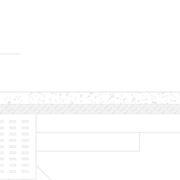
Under the 2015 IBC, section 1705.5.1 requires special inspection of high-load diaphragms designed and constructed in accordance with Section 2306.2. Per Section 1705.5.1, the special inspector is required to complete the following when inspecting high-load diaphragms: • inspect the wood structural panel sheathing to determine whether it is the grade and thickness shown on the approved construction documents • verify the nominal size of framing members at adjoining panel edges • verify the nail or staple diameter and length (Figure 1, page 23) • determine the number of fastener lines • verify that the spacing between fasteners in each line and at edge margins agrees with the approved construction documents (Figure 2) Additional special inspection requirements for high wind and high seismic areas are listed in
Metal-Plate-Connected Wood Trusses Spanning 60 Feet or Greater
The 2015 IBC section 1705.5.2 requires special inspection when a metal-plate connected wood truss has a clear span of 60 feet or greater. The special inspector is required to verify that the temporary installation restraint/ bracing, and the permanent individual truss member restraint/bracing, are installed in accordance with the approved truss submittal package. This section specifically requires that the owner or his/her authorized agent employ one or more approved agencies to perform inspections on the temporary and permanent truss bracing during construction to verify installation is in accordance with the truss submittal package.
Section 1705.11 requires special inspections for wood buildings in Exposure B areas where design wind speed, Vasd, as determined in accordance with Section 1609.3.1, is equal to or greater than 120 miles per hour; and in Exposures C & D areas where Vasd is equal to or greater than 110 miles per hour. Continuous special inspection is required during field gluing operations of elements of the main wind force-resisting system, and periodic special inspection is required for nailing, bolting, anchoring and other fastening of elements of the main wind force-resisting system, including wood shear walls, wood diaphragms, drag struts, braces and hold-downs. Section 1705.11.3 goes further to state that special inspections should include periodic inspection for fastening of the following systems and components: roof covering, roof deck, roof framing connections, exterior wall coverings, wall connections to the roof, and floor diaphragms and framing (Figure 3b, page 26). Section 1705.12.2 requires special inspections for wood buildings when the building is located in Seismic Design Categories C, D, E or F. In these Seismic Design Categories, continuous special inspection is required during field gluing operations of elements of the seismic force-resisting system and periodic inspection is required for: nailing, bolting,
ADVERTISEMENT–For Advertiser Information, visit www.STRUCTUREmag.org
RFEM 5
Dlubal Software, Inc. Philadelphia, Pennsylvania (267) 702-2815 info-us@dlubal.com www.dlubal.com Join us:
Structural Analysis and Design Software
Structural Congress February 14-16, 2016 German Engineering Precision. NASCC April 13-15, 2016 DOWNLOAD FREE TRIAL www.dlubal.com Designed for American Innovation.
BIM Integration Non-linear Analysis Dynamic Analysis

Figures 3a and 3b. Periodic special inspection is required for nailing, bolting, anchoring and other fastening of elements of the seismic and main wind forceresisting systems, including wood shear walls, wood diaphragms, drag struts, braces and hold-downs.
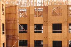
anchoring and other fastening of the elements of the seismic force-resisting system, including wood shear walls (Figures 3a and 4), wood diaphragms (Figure 3b), drag struts, braces, shear panels, and hold downs. Sections 1705.11.1 and 1705.12.2 further provide for an exemption from special inspection for wood shear walls, shear panels, and diaphragms, including nailing bolting, anchoring, and other fastening to other elements of the main wind force-resisting system where the diaphragm fastener spacing is greater than 4 inches. This exception is intended to exempt less highly-stressed lateral force resisting systems from special inspection. Additionally, a general exception to special inspection for seismic force resistance is provided in Section 1705.12 for buildings of light-frame construction not exceeding a building height of 35 feet and located in areas where SDS does not exceed 0.5. The purpose of special inspection requirements in these areas is to provide additional public safety in higher wind and seismic zones, and to provide assurance for the structural engineer of record and the building department that the structure is being built in accordance with the proper design and performance specifications. with all of the requirements of the approved construction documents. Structural observation does not waive nor is it an alternative to the inspections in Section 110 or the special inspection requirements in Section 1705. Typically, observation occurs during significant construction stages and at the completion of the structural system. The objective of the structural observation is to become familiar with the progress and quality of the contractor’s work, and then determine if the work is being completed in general conformance with approved plans and specifications. Observation is a contract-negotiated activity which is usually performed by the structural engineer as a part of the normal scope of services. Structural observations are mandated for certain high wind or high seismic areas, Risk Category III or IV buildings, and in other circumstances in accordance with IBC Section 1704.6. At the conclusion of the work included in the permit, the structural observer is required to submit to the building official a written statement that the site visits have been made and identify any reported deficiencies that, to the best of the structural observer’s knowledge, have not been resolved.
Conclusion
Requirement for special inspections in the model building codes have been mandated since 1961; however, special inspections pertaining to wood construction have only been required for the past twenty-five years. Structural provisions in the building codes, including those for special inspection, have evolved based on experience following natural and manmade disasters. Certain types of wood construction require special inspections per IBC Chapter 17. Most commonly specified wood products have quality control and third-party auditing procedures in place that exempt the manufacturer from these additional requirements. High capacity (blocked) diaphragms and applications for certain high wind and high seismic zones, however, are the most common examples where special inspections for wood construction are required. Part 2 of this article will provide perspectives from several States (based on the 2012 IBC) on suggested handling of special inspections regionally.▪
Structural Observations
When required by Sections 1704.6.1 for those structures assigned to Seismic Design Category D, E or F or Section 1704.2 for those structures sited where Vasd , as determined in accordance with Section 1609.3.1 exceeds 110 mph, structural observations are to be provided on a project. Structural Observation is the visual observation of structural systems by a Registered Design Professional (i.e., licensed engineer or architect) for general conformance with approved construction documents. Structural Observation is intended to assist and supplement the work of the Building Official. Structural Observation by itself does not certify, guarantee, or ensure conformance
Foundation Companies Had A GOOD 2015 and Look Ahead to
A STRONG 2016
STRONG DOLLAR MAY IMPACT OVERSEAS PROJECTS
By Larry Kahaner
In a solid market for foundation services, companies are ramp- At Geopier Foundation Company (www.geopier.com), President ing up new products and services to keep pace with demand. Kord Wissmann says that the ground improvement industry as a “Because foundations are the first step in construction, this whole is changing rapidly and interfacing with the structure engiindustry tends to experience trends a little bit before the rest of neering community in lots of ways. “It seems that this part of the the construction market. By analyzing economic trends, I suspect we’ll whole ground-support-for-structures segment is expanding rapidly. continue to see the American market recover and yield good results for Within our company we have two new things that SEs might like the foundation industry,” says Gina Beim, Senior Consulting Engineer to know about. One is within the rigid inclusion realm of things. and Marketing Director at Pile Dynamics, Inc. (www.pile.com). For We have developed something called a GeoConcrete Column that her own company, she notes: “Business has been good, but the strong is being used to support fairly heavy loads on very, very soft soil. dollar is affecting sales in some international markets, particularly in Most of that work is being done on the East coast, New England Asia. In the United States, however, sales increased in 2015 when compared to the previous year.” For 2016, Pile Dynamics will launch a Thermal Integrity Profiler (TIP) new product called SQUID. Beim says, The Heat Is On. “SQUID is a large device that attaches to the end of the Kelly bar used in foundation drilling, and assesses the quality of the bottom surface of the bored pile Shape, quality, cage alignment and concrete cover of drilled shafts. or drilled shaft hole. It is a disruptive New TIP Reporter Assesses the entire cross section, technology, in that this assessment is shows soil profi le and reinforcing cage. no blind zones. currently made qualitatively only – visually, by means of a video camera lowered down the hole. The SQUID instead measures stuff – it’s a quantitative assessment, Testing with the TIP is fast and is done soon after casting, so construction can move on. which, of course, engineers prefer. The Complies with ASTM D7949. device measures the thickness of any soft material or debris still to be cleaned from the bottom of the hole. It can also take some measurements that evaluate the strength of the bearing layer, which is the layer at the bottom of the hole where www.foundations.cc www.pile.com/tip the shaft is supposed to rest.” engineering@foundations.cc sales@pile.com

and the mid-Atlantic regions,” Wissmann says. “GeoConcrete Columns are a form of rigid inclusions which are becoming quite popular to support structures. These are foundation, systems that are neither deep foundations nor are they shallow foundations, but something in between. Sometimes, when traditional forms of ground improvement don’t quite do the trick, then rigid inclusion is being used, a ground improvement element that’s constructed with cement.” He adds: “The second item is improvements to our Rammed Aggregate Pier systems. We have a hybrid called the X1 system. It’s a way of constructing a Rammed Aggregate Pier where we can partially drill a hole and then use our tool to displace the remainder of the hole. This particular type of compaction device does a good job of compacting the Rammed Aggregate Pier in place. The advantage to SEs is that it’s a more efficient way of building Rammed Aggregate Piers, saving time and money on projects.”
ADVERTISEMENT–For Advertiser Information, visit www.STRUCTUREmag.org
Wissmann sees a trend towards increased use of ground improvement and more methods for SEs to choose from. “Business is up this year versus last year. Last year was a tremendous year for us, and this year is still better.” (See ad on page 32.) Eric Droof, President of Hayward Baker (www.haywardbaker.com) says that some engineers are still not familiar with all the ground improvement services that are available. “I think these things are still not well understood by consulting geotechnical engineers. Consulting geotechnical engineers typically don’t have the knowledge or skills to design these solutions. Some of the solutions include products like soil mixing, earthquake drains, jet grouting, aggregate piers and rigid inclusions.” He says these methods are typically replacements for deep foundations, or solutions for very soft or difficult soil conditions. “They offer lower cost, reduced time for construction, reduced cost for foundation construction, and they also offer seismic mitigation in conjunction with foundation support.” continued on next page
ADVERTISEMENT–For Advertiser Information, visit www.STRUCTUREmag.org
GROUTING Cement Grouting (High Mobility Grouting) • Chemical Grouting • Jet Grouting Compaction Grouting (Low Mobility Grouting) • Fracture Grouting • Polyurethane Grouting GROUND IMPROVEMENT Dry Soil Mixing • Dynamic Compaction • Injection Systems for Expansive Soils • Rapid Impact Compaction • Rigid Inclusions (Controlled Stiffness Columns) Vibro Compaction • Vibro Concrete Columns • Vibro Piers® (Aggregate Piers) Vibro Replacement (Stone Columns) • Wet Soil Mixing STRUCTURAL SUPPORT Augercast Piles Drilled Shafts • Driven Piles • Franki Piles (PIFs) • Helical Piles • Jacked Piers • Macropiles® Micropiles • Pit Underpinning EARTH RETENTION Anchors • Anchor Block Slope Stabilization Gabion Systems • Micropile Slide Stabilization System (MS3) • Secant or Tangent Piles Sheet Piles • Soil Nailing • Soldier Piles and Lagging ADDITIONAL SERVICES Earthquake Drains Sculpted Shotcrete • Slab Jacking • Slurry Walls • TRD Soil Mix Walls • Wick Drains

DESIGN-CONSTRUCT SERVICES
Says Droof: “Business is pretty good. Th e commercial markets in major urban areas have come back nicely. Places like New York, Miami, Atlanta and Los Angeles are all busy with the commercial sort of residential construction, as well as educational and hospital.” He says that the company is excited about a new project in lower Manhattan. “It’s a 55-story residential tower. We’ve just completed the jet grouting for it.” He says that the alternative would have been 190-foot deep drift shafts. “We believe it will be the fi rst high rise building in lower Manhattan that is not supported by a deep foundation.” At Adapt Corporation (www.adaptsoft.com), President Florian Aalami says: “We have made major advancements in our ADAPTBuilder software platform for integrated design of concrete buildings, in particular for the design of foundations using the ADAPT-MAT module. Structural engineers can now model a complete building, including all details of the foundation system. Global gravity and lateral analysis results are available for detailed foundation design, all within the same model, without requiring the need to fi rst export/import the solution between programs. Th is saves time and reduces errors often introduced when translating global building analysis results into separate foundation design programs. ADAPT-MAT can be used to design any type of foundation system.” Aalami notes that he sees a continuing trend towards BIM even though many practitioners are not completely clear about their BIM requirements. “We also continuously hear complaints about how it is much more effi cient to design and detail steel buildings, compared to what is possible for concrete structures. Th e potential to deliver ever more effi cient, complete
Geopier Ground improvement concrete design solutions is what keeps us motivated.” controls structure settlement As for business, Aalami says, “Th e U.S. market has been very strong this year, but we are seeing some softening in international markets. We largely attribute this to the slowdown in their economies and the weakening of many international currencies against the U.S. Dollar.” (See ad on page 28.) Th e company Subsurface Constructors (www.subsurfaceconstructors.com) has had a busy year, according to Lyle Simonton, Director of Business Development. “In addition to it just being an extremely busy year, Subsurface Constructors has had some exciting new experiences in 2015,” he says. “We completed Aggregate Pier ground improvement projects in several new states, including Washington, Alabama, and New Hampshire. We had some huge news with the opening of our New England offi ce, just outside of Boston. Having a physical presence in this region will help us to remain competitive Give your structure stability on bid day and provide better support to the engineering community.” Simonton adds: “More than ever before, Work with Geopier’s geotechnical engineers to solve your ground we are working directly with structural improvement challenges. Submit your project specifications to engineers during the design phase of receive a customized feasibility assessment and preliminary cost projects to help develop the optimum estimate at geopier.com/feasibilityrequest. foundation plan using Aggregate Pier ground improvement. We are providing 800-371-7470 them with specifi c project information regarding bearing pressures, which can be geopier.com achieved with Aggregate Piers.” info@geopier.com He says that Subsurface Constructors was fortunate to have been involved with several high profi le St. Louis area projects in 2015, including a large earth retention ©2016 Geopier Foundation Company, Inc. The Geopier® technology and brand names are protected under U.S. patents and trademarks listed at www.geopier.com/patents and other trademark applications and patents pending. Other project at the Gateway Arch foreign patents, patent applications, trademark registrations, and trademark applications also exist. and completing the ground improvement work for the St. Louis IKEA store.▪


A New Era of Women’s Health for Central Florida

By Kevin Casey, P.E., S.E., Bill Mitzo, P.E. and Nathan Morrow, P.E.
The Florida Hospital for Women is located on the main campus of Florida Hospital South in Orlando, FL. It is a 12-story, 430,000 square-foot facility dedicated to the health and well-being of women and new born children, with a 322-bed tower. Opened in December 2015, the facility includes 14 labor and delivery suites, 13 operating rooms for obstetric and women’s services, 72 postpartum care beds, mother-baby beds, high-risk beds and 80 neonatal intensive beds. The operating rooms accommodate robotic surgeries for obstetrics, including the da Vinci Surgical System for robotic minimally invasive surgery. The building is situated on a tight urban site bordered by CSX rail lines on the west, the 3-story Andersen Wing, an existing 40 year old hospital building, on the north, the 10 year old 7-story Walt Disney Pavilion for Children on the northeast corner, Rollins Street, a public street on the south and the main hospital entrance on the east.
Structural Frame
A cast-in-place concrete building was the preference of the hospital, based on their previous success with concrete construction. The benefits to the hospital include: • Inherent fire protection • Accommodates future modifications and changes of use, with minimal disruption to ongoing operations in a sterile environment • Inherent ability to dampen vibrations The project team evaluated two framing systems during the schematic design phase. Preliminary designs were prepared by Paul J. Ford & Company (PJF) for a conventionally reinforced 27-inch deep module joist and beam system (5-inch slab + 22-inch pans) and a 12-inch conventionally reinforced concrete flat plate. Post-tensioning was not considered as conventional reinforcing is more easily modified for future floor penetrations and openings required for healthcare
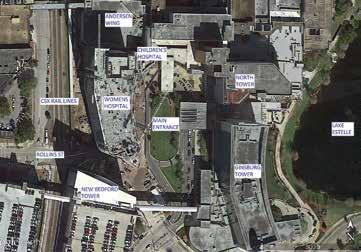
Figure 1. Campus plan. facilities. The designs were evaluated by the team and the flat plate was selected based on the following benefits: • Accommodated an irregular column layout dictated by the building’s unique curvilinear shape • Minimized the structural floor depth allowing increased interstitial space for high demand MEP systems necessary for a hospital • Reduced the overall height of the building by 12 feet, reducing the cost of the building envelope • Simplified the form work and reinforcing steel placement • Increased the speed of construction Columns are typically 30 x 30 inches from foundation to roof. Interior columns from the foundation to Level 7 are 30 x 36 inches. Concrete strengths varied from 7000 psi to 5000 psi. Concrete reinforcing steel was specified to be Grade 60 for bars up to No. 9 and Grade 75 steel for No. 10 and No. 11 bars. Specifying the higher strength steel for the larger bars eased congestion by reducing the required number of bars, and saved placement costs. The material cost for the Grade 75 bars was 4% greater than the Grade 60 bars. The primary lateral load resisting system is an ordinary concrete shear wall system. A “blade” shear wall was required at the south end of the building to supplement the stair and elevator cores, in order to maintain torsional rotation within allowable limits.
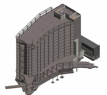
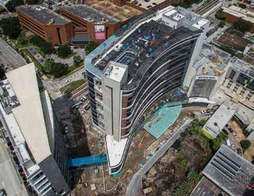
Figure 2. Isometric view of Revit model. Figure 3. Progress as of September, 2015.
An elevated pedestrian bridge located between the second and third levels connects the new hospital to the New Bedford Tower on the south end of the hospital. Escalators connecting the bridge lobby to the main lobby on Level 1 dictated the need for a transfer girder over the escalators. A one-story connector was included along the north east corner that connects to the existing Children’s Hospital.
Vibration Study and Design
Minimizing vibrations is a design consideration in all healthcare environments in order to assure a comfortable environment for patients, and is necessary to allow uninterrupted medical procedures. All healthcare facilities must be checked for footfall induced vibrations. The heavily traveled CSX rail lines located immediately to the west of the new Women’s hospital presented a unique design challenge to the team. Vertical vibration criteria used in the design were an ISO Operating Theater vibration criteria of 4000 micro-inches/second (mips) for patient rooms and other patient areas, and a VC-B vibration criterion of 1000 mips for the operating rooms on Level 2. A limit of 4000 mips is on the threshold of human perception. A limit of 1000 mips is suitable for micro-surgery, eye surgery and neurosurgery. Preliminary structural calculations indicated the building structure met the 4000 mips criteria for patient rooms and other patient areas due to footfall, but did not meet the 1000 mips criteria for the L2 operating rooms. It was estimated that a 27-inch beam and slab system would be required to meet the 1000 mips criteria from footfall. In order to measure the vibration effects from the adjacent rail lines and to conduct studies on the vibration performance of the building, RWDI was retained by the hospital. Part of that study included taking ground vibration measurements in the form of time-history accelerations and determining the vibration performance of the new hospital. RWDI created a model of the mat foundation and soil properties using the soil-structure interaction software Dyna5.4. A shear-wave velocity of 660 fps, provided by Terracon, the project geotechnical engineer, was used for the soil surrounding the foundation. The measured time-history accelerations were applied to the Dyna5.4 model and the response of the foundation was then used as an input load to a SAP2000 finite element model. PJF’s ETABS model was used to generate the SAP2000 finite element model that was modified for dynamic analysis. The velocity responses were determined at specific points in the SAP model. These records were processed by RWDI to determine the expected vibrations in 1/3 octaves for several representative trains at various locations in the building. Three types of trains travel the rail lines; passenger, freight and heavy freight trains. The predicted vibration levels on Level 1 and Levels 3 through 12 achieved the required 4000 mps criterion. The predicted vibration levels on Level 2 achieved the required 1000 mips criterion for the passage of passenger trains and freight trains. The predicted vibration levels on Level 2 due to the passage of a heavy freight train exceeded the required 1000 mips criterion for that level. Vibration mitigation was implemented on Level 2 by stiffening the floor system to a 24-inch deep beam and slab (12 inch slab and 12 inch pan) system. Additional measures were evaluated to further mitigate vibration from the heavy freight trains including a base isolation system, isolating the rail lines, or constructing a deep slurry wall between the building and the rail lines. The base isolation system was not a viable option, as it was cost prohibitive. Isolating the rail lines or constructing a deep slurry wall may be implemented in the future, if deemed necessary by the hospital.
PJF and Terracon worked closely together on the foundation design for the new facility to arrive at a system that saved two months on the construction schedule. Four foundation systems were considered for the hospital; auger cast piles, auger cast displacement piles, a mat foundation on improved soils, and a mat foundation. Preliminary designs were carried out for a deep foundation system with auger cast displacement piles and a mat foundation. The deep foundation system utilized 18-inch diameter, 50-foot long, auger cast displacement piles with a capacity of 100 tons. In addition to the construction of the piles and pile caps, a 2-foot thick heavily reinforced slab was required to resist the hydrostatic pressure due to the high water table common throughout Central Florida. The mat foundation was designed to be 5 feet thick, sufficient to resist the hydrostatic pressure and punching shear from the columns. PJF and Terracon worked together to evaluate the need for rigid inclusions under the mat to minimize overall settlement and differential settlement. The settlement for the mat without ground improvement was initially predicted to be on the order of 3 to 4 inches.
The team decided the predicted settlement was within an acceptable limit, and that further study of a mat foundation without ground improvement was warranted. PJF and Terracan proceeded to study the mat foundation. The study was conducted based upon the following parameters: • The mat (raft) foundation was supported on ground without deep ground improvement elements, i.e., no rigid inclusions or similar ground improvement elements were included in the analysis. • The thickness of the mat foundation was 5 feet. • The modulus of sub-grade reaction values, i.e., the spring constants, ranged from 6 pci at the interior of mat foundation to 12 pci at the perimeter of the mat foundation. • Four iterations of calculations were conducted between PJF and Terracon in order for settlement results to converge between the structural model and geotechnical model. The structural engineer utilized SAFE and ETABS for its analyses, and the geotechnical engineer utilized PLAXIS for its analyses. The results of the study are summarized as follows: • The total settlement of the mat foundation was predicted to be in the order of 2.5 inches at the interior core area at the patient elevators to 0.90 inches along the east edge of the mat. • Approximately 25% of the expected total settlement will occur due to the weight of the mat prior to the casting of the Level 1 structural slab. • The expected differential settlement in the mat was a slope rate of 0.002 or L/500. • The settlement of the structure along the existing Anderson
Building and Disney Pavilion was expected to in the order of 0.75 inches to 1.50 inches. • The maximum contact pressure below the mat foundation was 3800 psf. The calculated settlement values were conservative and are on the upper bound of the expected actual values based upon previous experience with similar projects. The project team concurred that the settlements were within acceptable limits.
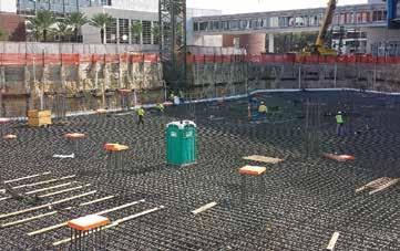
Figure 4. Mat preparing for concrete placement.
Project Team
Structural Engineer of Record – Paul J. Ford & Company Owner – Florida Hospital Office of Design and Construction Architect – HKS Gerneral Contractor – Brasfield & Gorrie
The three story areas of the building on the south and east elevations were supported by shallow foundations. Construction of these areas of the structure was phased to occur simultaneously with the construction of the final three levels of the tower, in order to minimize the risk of differential foundation settlement.
Conclusions
Measurement during construction indicated the overall settlement of the mat averaged about 1 inch with minimal differential settlement. The majority of the settlement occurred during construction of the building frame, as predicted. Schematic design of the new Florida Hospital for Women started in April, 2012. Construction broke ground on January 9, 2013. Concrete for the mat foundation was placed on February 8, 2014 and the concrete frame topped out October 31, 2014. The hospital opened in December, 2015. The Florida Hospital for Women introduces a whole new era of high-technology care for the women of Central Florida.▪
Kevin Casey, P.E., S.E., is a Vice President and can be reached at kcasey@pjfweb.com. Bill Mitzo, P.E., is an Engineering Manager and can be reached at bmitzo@pjfweb.com. Nathan Morrow, P.E., is a Project Manager and can be reached at nmorrow@pjfweb.com. All three work in the Orlando office of Paul J. Ford & Company.
STRUCTURAL REPAIRS for COURTHOUSE SQUARE
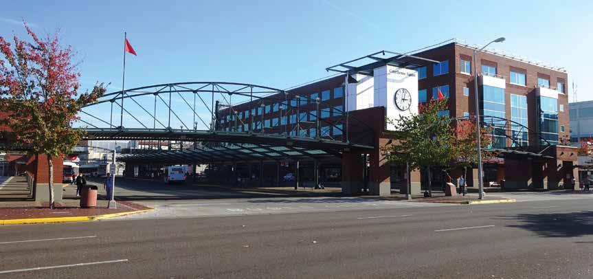
By Tarek Alkhrdaji, Ph.D., P.E.
Completed complex.
The Courthouse Square complex, located in the heart of Salem, Oregon, is owned by Salem-Keizer Transit and Marion County. The complex occupies an entire city block and consists of three structurally independent, architecturally contiguous structures; a five-story office building, a transit mall, and a future development site (North Block). An existing belowground parking facility extends under the three structures and occupies the entire block. The complex was first opened to the public in September 2000. The original floors and roof of the office building consist of flat plate, 10-inch thick post-tensioned concrete slabs, supported by reinforced concrete columns and a perimeter reinforced concrete foundation wall at the basement level. The lateral force resisting system for the building consists of shear walls surrounding the two stairwells that are supported by a 5-foot thick reinforced concrete mat foundation. The transit mall and the North Block are one-story below-grade reinforced concrete structures constructed with 10-inch elevated posttensioned slabs. The approximately 60,000 square-foot transit mall slab consists of six individual slabs segments that were constructed with no pour strips between slabs. The post-tensioned slab was originally coated with a waterproof barrier and topped with a thin concrete overlay, a sand blotting layer, and brick pavers. The North Block slab has bonded post-tensioning with a 3-inch thick topping. Both structures are supported by 12- by 12-inch reinforced concrete columns and by the perimeter reinforced concrete foundation walls. Between November 2012 and March 2014, the Courthouse Square complex went through a significant structural and building envelope rehabilitation program. The structural program included remediation to existing slabs, columns, lateral load resisting system, isolated column footings and matt foundation, and building envelope.
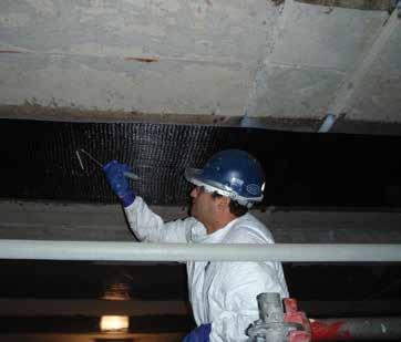
A Complex in Distress
Issues with the building and transit mall began to emerge in 2002. Cracks started to appear on interior partition walls and on the concrete foundation walls, and floor tiles started to crack and buckle. Deflections up to 3.5 inches were measured on existing slabs. The paving stones on the bus mall were shifting and settling. Over the next eight years, several separate engineering studies were initiated to assess the structure. Most reviews concluded that, while repairs were necessary, the complex remained structurally safe to occupy. In January 2010, a comprehensive assessment of the structural and serviceability problems was conducted and concluded that the original design of the complex was inadequate in several areas. Field investigation and detailed analysis confirmed the presence of significant structural/life-safety issues within the structure. A significant number of columns in the building were overstressed and prone to axial and bucking failures, and some slab locations were significantly overstressed in punching shear; one slab location exhibited signs of punching shear failure. The building envelope showed signs of water infiltration around windows and damage due to building movement. The brick masonry system exhibited compression of the expansion joints, and the brick façade appeared to be pushed out. Clear separation was observed at slab-to-curtain-wall connections, indicating excessive shrinking and shortening of the post-tensioned floor slabs. The bus mall exhibited significant structural issues as well, most notably excessive foundation wall cracking, two rows of end columns that were leaning inward and several columns with significant and pronounced cracks. One of the major concerns was
the safety of the transit mall slab which was found to be significantly overstressed in bending and punching shear, making the use of the facilities unsafe. In July 2010, Courthouse Square was closed, offices and services were relocated to other buildings, and the complex was declared too dangerous for the public. A task force comprised of transit, county, and citizen representatives was appointed to evaluate remediation solutions and explore alternative uses for the site. Initial repair estimates exceeded $49 million, while the cost to demolish and replace the building was estimated at $56 million. Remediation was favorable because the site of the complex is a centralized, easily accessible location in downtown Salem. Considering the complexity of the project, a three-tier design-build-bid process was developed by the owners. In the first phase, qualified design-build teams were selected and approved based on pre-established requirements for experience with evaluation and rehabilitation of structures with similar types of problems. In Phase 2, the selected teams submitted detailed reports that included review of the results of field assessment reports, performing preliminary structural analysis, identification of existing deficiencies, and development of remediation approach and cost estimate. In Phase 3, the teams were interviewed by a special panel that included the owners and third party reviewers in order to evaluate the design-build proposals and select a successful bidder. Structural Preservation Systems, LLC (STRUCTURAL) along with Whitlock Dalrymple Poston & Associates (WDP) were selected to lead the design-build team to complete the $22.9 million remediation in 2012.
Structural Deficiencies and Remediation Methods
Remediation work for Courthouse Square was carried out based on the 2009 International Building Code (IBC 2009) – Oregon Structural Specialty Code, the 2008 edition of the American Concrete Institute’s (ACI) Building Code Requirements for Structural Concrete (ACI 318-08), and Minimum Design Loads for Buildings and Other Structures (ASCE 7-05), along with seismic hazard data from the United States Geological Survey. Modeling and analysis were performed using SAFE and SAP2000 software for nonlinear analysis of the existing structure. The main structural deficiencies and remediation techniques used to bring the structure to current standards included: • Isolated Footings – several of the existing column footings were found to be deficient in punching shear and in bearing capacity. These issues were resolved by enlarging the size and depth of the existing footings to increase their shear, flexural and bearing strengths. • Slab Punching Shear – Deficiencies were identified at numerous locations throughout the building, including significant shear deficiencies at the transit mall slabs. Slab remediation was achieved utilizing cast-in-place concrete drop panels. A specialized technique was required to prepare the concrete surfaces and to place the concrete material in order to guarantee proper bond between the new and existing concrete – known as the form-and-pump technique. The size of the drop panel was proportioned to satisfy strength increase requirements and to minimize interference with existing mechanical, electrical and plumbing (MEP) systems. Steel dowels were used to supplement the bond between new and existing concrete, and improve load transfer to existing columns. • Column Capacity (Slenderness and Strength) – Analysis indicated that a majority of the columns were deficient in
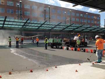
Crews apply a traffic-bearing coating in the public transportation area.
Columns wrapped with FRP for axial strength and enlarged for punching shear.
Enlargement systems were used to strengthen the column footers in the parking structure.
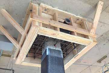
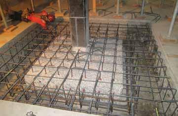
axial and/or bending strength, or did not satisfy stiffness requirements. Column strengthening was achieved by installing 6- to 10-inch thick reinforced concrete jackets to increase the axial and bending strengths, and to increase buckling resistance of the columns. Similar to drop panels, the concrete jacket was placed using the form-and-pump technique. Specialized self-compacting concrete (SCC)
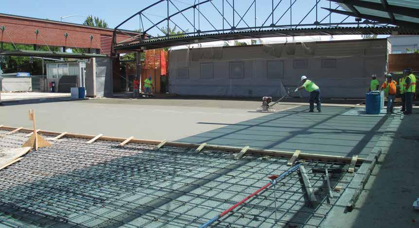
Placement of bonded overlay over the parking structure created a strengthened deck for the public transportation area. material was developed, and used to pressurize the formwork and to produce optimum bond between the existing and new concrete. The size of the concrete jacket varied to satisfy strength requirements and to minimize interference with the existing MEP, building finishes, and parking spaces. Onesided, two sided, and full jackets were used, as needed, to address these conditions. • Slab Bending Capacity – Several locations were identified that required additional tension reinforcement at the top or bottom sides of existing slabs. Flexural strengthening of slabs was achieved using externally bonded fiber reinforced polymer (FRP) reinforcement. The V-Wrap externally bonded FRP composites supplied by Structural
Technologies provided a very low profile and did not change the appearance of the slabs or interfere with floor finishes.
The design of the FRP was achieved using the industryrecognized ACI 440.2R-08 design guide. • Shear Walls – Deficiencies were identified on shear walls located on the west core of the office building. Strengthening of deficient walls was achieved by epoxy injection of existing cracks in addition to using concrete enlargement, bonded FRP reinforcement, or a combination thereof. The choice of the strengthening solution varied, and depended on the existing wall capacity and required strength increase. Form-and-pump concrete placement techniques were used to ensure proper load sharing between existing walls and new enlargements. • Mat Foundation – The mat foundation supporting the west core element was found to be deficient in bending.
Strengthening was achieved using micropiles that were placed through the existing mat foundation to improve its load carrying capacity. Strengthening of the transit mall slab included removal of the existing concrete overlay, sand and pavers, and installation of a new 5-inch thick bonded overlay, increasing the slab thickness from 10 inches to 15 inches. To ensure composite performance of the existing slab with the new reinforced topping, the topside of the existing slab was roughened to ¼-inch amplitude, and steel dowels were installed in both directions. Using this approach, the total superimposed dead load was reduced while increasing the flexural and punching shear capacities of the slab. The concrete overlay was finished with an epoxy-based heavy traffic coating. Cast-in-place shear capitals were also installed at several columns where high punching shear deficiency was identified. In addition, externally bonded FRP was utilized at the mid-span regions to increase the flexural capacity of the slab. All existing foundation wall cracks were repaired using epoxy injection.
Building Envelope Repairs
The design-build team concluded that several of the building envelope issues were caused by the relatively high post-tensioning forces in the slabs. Over time, the large post-tensioning forces in the slabs resulted in excessive elastic shortening and creep of the slabs. The detrimental side effect of slab shortening is the distress it caused in the brick façade, as well as high shear forces on columns located near the expansion joints. The compressive stress in the slabs due to post-tensioning varied between 350 psi and 500 psi. The long-term elastic shortening of the slab due to these forces was estimated using the GL2000 model provided in ACI 209.2R-08. Using this approach, an elastic shortening of 0.7 inches was estimated to occur at each end of the slab after 12 years. This calculated value compared well with the field-measured shortening of 0.75 inches at a slab edge. As the long-term slab shortening was considered to be complete after 12 years, the overall repair approaches served to address distressed and displaced building envelope components. Additional shortening that may occur over the remaining service life of the structure was accounted for by installing additional strip joints onto the masonry façade, as well as widening existing joints. Repairs to the façade included replacement of the 5th floor brick façade, flashing repairs
at window perimeters and shelf angles, and replacement of severely cracked/damaged window frames. Replacement and stabilization of significantly displaced brick panels on lower floors were also completed.
Conclusions
Delivery of a structurally safe complex, with sound engineering and a 50-year service life, was a primary focus of the owners. To this end, a third party consultant was hired to be the owners’ representative, ensuring a rigorous quality assurance program as the project progressed. Over the course of the project, up to 100 construction workers were at the project site to perform the repairs. Throughout the project, a series of four stages of inspection process were developed that occurred during the construction of each repair. Repairs moved forward to the next phase only when inspectors representing the various parties were satisfied with the quality of completed work. Courthouse Square has been described as a model design-build structural repair project with design professionals, contractors, and vendors all focused on delivering a successful result. After eighteen months of construction, the Courthouse Square complex was reopened in April 2014, on schedule and within budget. In 2014, the Courthouse Square project recieved an Award of Excellence by the International Concrete Repair Institute and was also a Project of the Year Finalist.▪
Tarek Alkhrdaji, Ph.D., P.E., is Vice President of Engineering with Structural Technologies. Dr. Alkhrdaji is an active member of ACI Committee 437 (Strengthening Evaluation) and ACI 562 (Repair Code); and he is the past Chair ACI 440F (FRP Strengthening). He can be reached at talkhrdaji@structuraltec.com.
Project Team
Engineer-of-Record for the Structural
Remediation: WDP & Associates Specialty Repair Contractor / General
Contractor: Structural Preservation
Systems LLC Local Subcontractor: Dalke
Construction, Inc., Carlson Veit
Architects, P.C., MSC Engineers,
Inc., and Environmental and
Engineering Services

State-of-the-Art Products
STRUCTURAL TECHNOLOGIES provides a wide range of custom designed systems which restore and enhance the load-carrying capacity of reinforced concrete and other structure types, including masonry, timber and steel. Our products can be used stand-alone or in combination to solve complex structural challenges.
V-Wrap™
Carbon Fiber System
DUCON®
Micro-Reinforced Concrete Systems
VSL
External Post-Tensioning Systems
Tstrata™
Enlargement Systems
Engineered Solutions
Our team integrates with engineers and owners to produce high value, low impact solutions for repair and retro t of existing structures. We provide comprehensive technical support services including feasibility, preliminary product design, speci cation support, and construction budgets. Contact us today for assistance with your project needs.
www.structuraltechnologies.com +1-410-859-6539
To learn more about Structural Group companies visit www.structuralgroup.com DUCON® trade names and patents are owned by DUCON GmbH and are distributed exclusively in North America by STRUCTURAL TECHNOLOGIES for strengthening and force protection applications. VSL is the registered trademark of VSL International Ltd.
INTEGRATING
SUSTAINABILITY STRUCTURE &
A Case Study
By Keith T. Bauer, S.E.
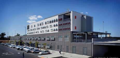
The Sacramento Municipal Utility District East Campus Operations Center (SMUD ECOC) is a six building, 350,000 square foot facility on a 51 acre site in Sacramento, California that was completed in May 2013. Th e project served to relocate the operations headquarters for SMUD to a more centrally located and larger facility which would increase operational effi ciency. SMUD also sought to lead by example by achieving LEED Platinum certifi cation and Net Zero energy usage for sustainability. Th e project was awarded to Turner Construction and the design-build team of Stantec (lead architect, mechanical, electrical, and plumbing designs), RNL (sustainability and yard building architect) and Buehler & Buehler Structural Engineers, Inc. (structural) based largely on the team’s innovative use of an integrated structural and mechanical system which leveraged the use of the thermal mass of the concrete to reduce energy consumption. Th is design methodology was identifi ed through the use of Integrated Project Delivery (IPD), and ultimately required the smallest area of photovoltaic panels.
Yard Buildings
Th e yard buildings consisted of approximately 150,000 square feet of new construction spread amongst fi ve primary structures: Fleet Maintenance, Tools/Shop, Warehouse, Electrical, and Truck Wash. Structural considerations for these buildings centered on use of costeff ective structural systems (open web joists, precast concrete panels, cold-formed steel canopies), providing accommodations for bridge cranes within the structures, and minimizing thermal bridging through detailing to enhance the energy effi ciency of the buildings. A thermal bridge is defi ned as an area of a building component which has a signifi cantly higher heat transfer than the surrounding materials, resulting in an overall reduction in thermal insulation of the object or building. For the yard buildings, the main source of thermal bridging was the connection of the shade canopies at the building perimeter to the exterior precast insulated concrete sandwich panels. Th e concrete wall panels consisted of a structural wythe (thickness varied dependent on building height and loading demands), 2½ inches of insulation and a 2½-inch architectural wythe. Th e thin architectural wythe was insuffi cient for anchorage of the perimeter shade canopies, therefore isolated areas of full-thickness concrete that penetrated the insulation layer were required. Th ese canopies were integral to the sustainable design of the structures. Th e shading elements controlled heat gain by preventing direct sunlight from entering interior space, while still allowing enough natural light to reduce the need for powered interior lighting. Th e IPD project environment allowed B&B’s structural engineers to work concurrently with the architects and energy modeling team to fi nd a structural solution that met canopy anchorage demands, achieved the architectural aesthetic, and minimized the thermal bridging that was incorporated in the energy model. Th e canopy attachment detail is shown in Figure 1.
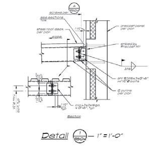
Offi ce Building
Th e largest structure on the site is the six-story offi ce building, a fourstory tower over a two-story podium housing over 200,000 square feet of offi ce space, a large conference/meeting space, cafeteria, and an emergency operations center at the upper level. Although not directly specifi ed, the original project Request-for-Proposal implied that the offi ce building was anticipated to be designed of steel. However, through coordination fostered by the IPD process, the concept of using radiant cooling that utilized the thermal mass of a concrete structure was developed and implemented. Th ere were several advantages to using this integrated structural and mechanical system. Th e thermal mass of the concrete structure allows the building itself to store and release heat at a rate similar to that of its environment. Th e ability of concrete to store heat during the warmest part of the day and release it as the ambient temperature cools at night reduces the need for mechanical climate control. Secondly, the energy required to move water through radiant tubing in the slab is less than traditional mechanical systems that push air. continued on next page
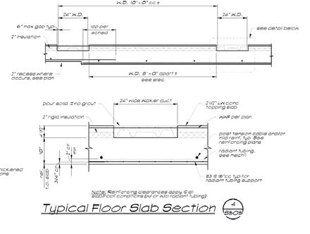
Figure 2 Typical slab detail. with regard to providing a large open meeting space at the ground level as required per the RFP. The meeting space required 67-foot clear spans which were not possible utilizing a two-way post-tensioned slab. Additionally, due to story height limitations, using concrete beams or girders at the second floor was also not an acceptable design solution. To solve this issue, it was decided to suspend the second floor from the roof structure above. This was achieved by providing two upturned post-tensioned concrete girders with tube steel hangers at third points from which the second floor post-tensioned concrete deck was supported. To clear span 67 feet, the required girder depth was 5 feet 6 inches; this was not well received architecturally, as the girder would project over the parapet wall. Therefore the girder design was modified to provide a two-way taper at the south end (adjacent to the parapet); the girders were reduced in depth while increasing in width to maintain the necessary shear capacity and the beam-column interface. An elevation of the girder is shown in Figure 3.
Air is circulated within the office building, but only by use of ceiling fans. Initially, the team proposed that, with the use of ceiling fans, the ambient temperature inside the building could be maintained at 82 degrees Fahrenheit. Ultimately, the owner decided that an ambient temperature of 78 degrees would be satisfactory. Compared to traditional forced-air office ambient temperatures in the range of 70-74 degrees, this increase in allowable ambient temperature also resulted in significant energy savings. The structural detailing of the radiant slab system is shown in Figure 2. The total slab section consists of a 10-inch thick 2-way post-tensioned slab. The bottom 2 inches of the slab is considered to be non-structural, as the radiant tubing is located in this zone. Because of the owner’s requirement to use a ‘walker duct’ system (for distribution of electrical and IT) at each floor, a topping slab over lightweight insulation was used to provide a flat finished floor surface. This insulation also served as an aid in managing the directionality of temperature control between floors. Although the thermal mass of the concrete structure was a major benefit to the mechanical design, the connection of the post-tensioned floor slabs to the exterior concrete shear walls presented a ‘thermal bridging’ design challenge. To mitigate this thermal bridge, the bottom 2 inches of the non-structural portion of the floor slabs were omitted and filled with insulation that protected a suspended radiant tubing system. The width of the slab recess was defined through thermal gradient models, which determined at what point the external and internal temperature difference was sufficiently dissipated so as to not adversely affect the performance of the radiant slab system.
Energy Model and Monitoring
Taking into account the structural systems, thermal bridging, anticipated demands as provided by the owner and the anticipated MEP design, the MEP team created a sophisticated and detailed energy model using the TRNSYS platform. As various components of the design evolved, the energy model was updated in real time to determine the amount of photovoltaic panels that would be required to meet the calculated energy demands and achieve ‘netzero’ energy consumption. The main limitation to the energy model was its dependence on anticipated energy use information provided by the SMUD user groups. This included such detailed information as anticipated plug loads, frequency of roll-up doors at the yard buildings being opened and closed, and hours of operation at a site whose function is to be able to be at full use at a moment’s notice in the event of a storm or power outage. SMUD elected not to fully fund monitoring that would enable detailed tracking of power usage in comparison to the anticipated use information provided. Although global energy consumption on site can be monitored, specific usage cannot be tracked and adjustments made to ensure the site is operating at its maximum efficiency.
Girders
Although the use of a concrete two-way flat slab for the building structural system had many advantages from an energy standpoint, it created a tremendous challenge
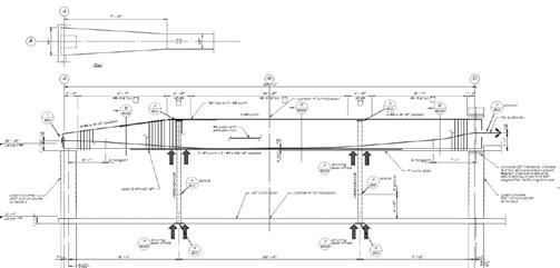
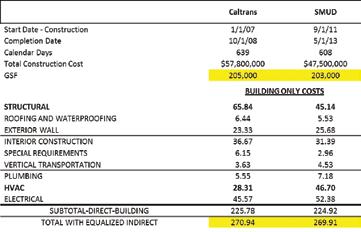
Figure 4. Building cost comparison between the SMUD ECOC and a similar office building.
Conclusion
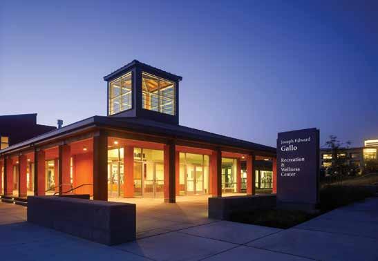
There is a common misperception that sustainable design equates to increased cost of construction. Based on energy modeling, the SMUD ECOC buildings consume 60% (office building) and 40% Figure 5: Annual energy cost comparison. (yard buildings) less energy than an ASHRAE 90.1 code design at comparable initial construction cost to similar buildings. Figure 4 provides a comparison between the SMUD ECOC and a project Turner Keith T. Bauer, S.E., is an Associate Principal with Buehler & Construction completed in northern California four years earlier. Buehler Structural Engineers, Inc. Keith also enjoys mentoring high Project square footage, construction duration, and usage between school students as part of the ACE Mentor Program of Sacramento the two buildings were similar. While SMUD was certified LEED and is an adjunct lecturer at the University of California at Davis. Platinum with Net Zero energy usage, the Caltrans project achieved He can be reached at kbauer@bbse.com. a LEED Silver rating. As shown in the figure, the MEP cost for the SMUD project was significantly higher than for the Caltrans project, as would be expected due to the high efficiency and technologically advanced systems required to achieve the target energy goals. However, due to a significantly lower structural cost on the SMUD project, the overall cost per square foot for the buildings is almost identical. The efficiencies in the design and construction of the SMUD project also resulted in reduced annual maintenance costs. Figure 5 shows the annual energy costs of a “code minimum” building, LEED Silver building (Caltrans) and Net Zero, LEED Platinum building (SMUD). Based on energy modeling, the annual energy costs for the SMUD project are approximately 55% of the Caltrans project and 33% of a code University of California, Merced Joseph E. Gallo Recreation and Wellness Center, Photograph © 2015 Tim Griffith Merced, CA minimum project. Overall, the SMUD ECOC project demonstrates how integrated structural and mechanical systems can lead to an optimum sustainable design, with reduced annual operating costs and building construction costs SUPPORTING INNOVATION IN ARCHITECTURE Seattle • Tacoma • Lacey • Portland • Eugene Sacramento • San Francisco • Los Angeles • Long Beach • Pasadena • Irvine • San Diego • • comparable to those of less Boise • Phoenix • St. Louis • Chicago • New York energy efficient code miniKPFF is an Equal Opportunity Employer. www.kpff.com mum structures.▪
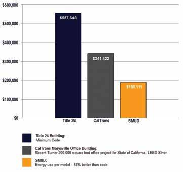

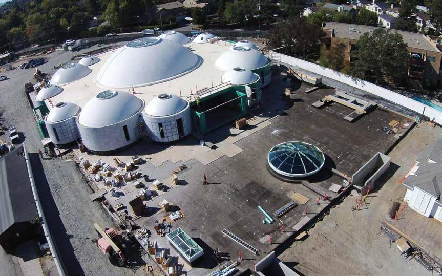
By Steve Ratchye, P.E., S.E., R.A., LEED AP BD+C and Graeme Ballantyne, P.E., S.E., LEED AP
Figure 1. Aerial photograph during construction. Courtesy Sufi sm Reoriented.
Decades in conception and planning, the new Sanctuary for Sufi sm Reoriented in Walnut Creek, California, aims for a design life of centuries. Th e Sanctuary consists of a series of one-story domes above grade and a basement below (Figure 1). Th e largest dome is 78 feet in diameter and covers the column-free Prayer Hall, and smaller domes cover a variety of other spaces around the perimeter. A striking 38-foot tall base-isolated bronze sculpture reaches up from the basement to the oculus of one of the medium domes. In an eff ort to fi t into the surrounding residential neighborhood, the above-grade structure is much smaller than the basement (Figure 1). Th e below-grade level features a sky lit rotunda, a gallery, offi ces and a recording studio. Th e building will serve as the principal center of worship for Sufi sm Reoriented, a religious group with congregations in the San Francisco Bay Area and Washington, D.C. Th e congregation collaborated with Philip Johnson/Alan Ritchie Architects and Th ornton Tomasetti as structural engineer, and hired Soga + Associates as the architect of record.
Elongated Design Life
Cast-in-place concrete was selected for the building, a choice infl uenced by the owner’s desire for an elongated design life with minimal maintenance. Other materials such as structural steel, precast concrete and concrete masonry were judged to be less durable for a variety of reasons, and therefore unsuitable. Th e smallest domes stand as the exceptions and consist of precast glass-fi ber reinforced concrete. When the owner initially expressed a desire for a design life in the range of hundreds of years, the structural designers recommended the use of
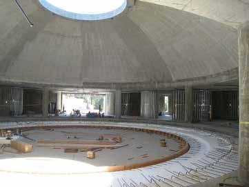
Figure 2. Main dome over Prayer Hall during construction.
performance-based design concepts because of the high seismicity of the site. Sufi sm Reoriented decided not to pursue this design option, but they did maintain their desire for a more robust approach than minimum code compliance. Th ey understood that, although the code aims at life safety for occupants, signifi cant damage to the structure may occur during a major seismic event. As a result, the building was designed using an R-factor of 1.25, the lowest response modifi cation coeffi cient in the California Building Code (CBC), rather than the R-factor of 5 for special reinforced concrete bearing walls. Th is approach reduces the ductility demands on the structure and aims to keep seismic forces largely in the elastic range of reinforced concrete.
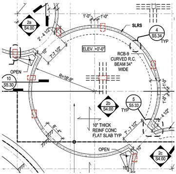
Figure 3. Partial plan of drum wall on columns below.
Seismic Design of Shear Walls and Domes
Special reinforced concrete shear walls that are circular in plan serve as the lateral system for the above-grade portion of the Sanctuary. The twelve “drum walls” occur below the four 38-foot diameter medium domes and the eight small domes. The main dome sits on columns, as shown in Figure 2, and is stabilized by a concrete flat slab diaphragm at roof level that transfers the seismic forces to the drum walls. Because the basement has a rectilinear geometry, the drum walls typically sit on columns below (Figure 3). In addition to serving as shear walls, the 12-foot high drum walls act as beams spanning between the basement columns. The drum walls supported on columns were treated as discontinuous lateral system elements for design, and seismic forces acting on the columns were designed for the CBC’s over-strength load combinations. The ground floor slab serves as a diaphragm to redistribute shears from the drum walls to the perimeter retaining walls, which serve as shear walls. Boundary zones were detailed within the drum walls where the stress criterion in ACI 318-08 Section 21.9.6.3 was exceeded, and typically these elements occurred where drum walls sit on columns. Because of the way the drum walls intersected in plan, some of the boundary elements have unusual configurations (Figure 4). Additional vertical dowels were added to anchor the drum walls into the supporting columns for uplift loads. A dome is such a stable structural form that an extremely thin shell is possible but, out of consideration for very long term durability, two mats of reinforcing were used with a minimum thickness of 7½ inches. The architects set the relatively shallow partial-sphere geometry of the domes initially, and it was confirmed by structural analysis. The domes and drum walls were modeled by finite element analysis with special attention paid to the intersections between the domes and the flat slab at the roof (Figure 5). The Morley Clark Nielsen method was used to calculate reinforcement for the domes from finite element results. Monolithic ring beams occurred at the top and bottom of each dome in order to carry the compressive and tensile hoop stresses respectively.
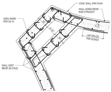
Figure 4. Boundary zone at drum wall.
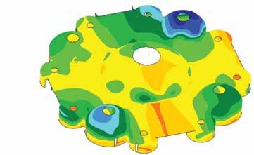
Figure 5. Finite element model of domes and drum walls.
Small reinforcing bars were detailed in the domes, and in their top and bottom ring beams, in order to facilitate bending them to a curve. Similar reinforcing bar sizes were specified for the curved bars in the drum walls. In addition, the clear cover specified was one-half inch larger than that required in ACI 318 in order to give the contractor more tolerance for rebar erection. Formwork for the domes consisted of closely spaced radial ribs of dimensional lumber, cut to curve and spliced. Thin plywood forms cut in wedge shapes were bent to curve and fastened to the ribs. The ribs were propped by conventional shores, which were braced at regular intervals for lateral stability. The concrete ring beams at top and bottom were placed first in order to insure that they, rather than the formwork, bore hoop stresses resulting from the wet concrete of the dome. The contractor shotcreted the domes in alternating pie-slice segments in order to minimize cracking from circumferential shrinkage. Domes constructed with inflated formwork were considered by the owner, but the only version that held promise for economy included an integral roofing system that was considered to lack the desired long term durability. The smallest domes are ¾-inch thick glass-fiber reinforced concrete with ribs. They are exposed to the elements, so thermal issues required
Figure 6. New Man sculpture. Courtesy Sufism Reoriented. Figure 7. Interior of triple friction pendulum isolator.
consideration. The other domes, on the other hand, are covered by roofing and insulation and are more massive, which prevents large temperature swings. Oversized bolt holes with Teflon shims at the base connections of the GFRC domes insured that the thin shells could expand and contract from temperature swings without being overstressed.
Buoyancy
A recommended water table 10 feet below grade and a basement roughly 20 feet below grade, coupled with a single story above grade or none at all, made hydrostatic uplift a significant issue. A concrete mat foundation was chosen because of its mass and the flexibility it afforded for future column placements during renovations. Additional ballast came in the form of a green roof over the ground floor slab outside the footprint of the above-grade story (approximately 250 pounds per square foot) and an eighteen-inch layer of gravel with a finish slab on top of the mat. Utilities such as plumbing lines were placed in the layer of gravel, which allowed for relatively easy future access. Near heavily loaded columns, the mat was thickened by placing pads on top of the mat within the gravel layer, which minimized excavation. Concrete for the mat slab was required to reach a 4000 psi compressive strength at 56 days. The longer than usual time period for the achievement of design compressive strength allowed for the use of less portland cement, just 282 pounds per cubic yard, and an equal proportion of Class F fly ash to create a more environmentally friendly mixture.
Sculpture
One of the highlights of the sanctuary is a 38-foot high bronze sculpture designed by a member of the congregation. The cloth-textured base of the sculpture supports the body, from which branches with butterflies rise to the full height (Figure 6). The body has numerous long holes cut in the surface, some as long as 15 feet. The highest butterflies are acrylic, the only portion of the sculpture that is not bronze. As with the building structure, the owner desired a long design life for the sculpture. Using the CBC provisions resulted in bronze thicknesses of one inch. However, the fabricator stated it was not feasible to cast a structure that thick. To reduce seismic forces and therefore the bronze thicknesses, Thornton Tomasetti suggested base-isolating the sculpture. Baseisolating the sculpture significantly lengthens the dynamic period of the sculpture and reduces the seismic forces. Friction pendulum isolators were selected because they use durable materials such as stainless steel and graphite, and are understood to return to equilibrium after a seismic event (i.e. self-centering). The isolator supplier recommended four triple pendulum isolators for the sculpture (Figure 7). Each of the three surfaces of these isolators is tuned for a different type of seismic event: frequent smaller earthquakes, the design basis earthquake and the maximum considered earthquake. The upshot of this careful tuning is a fatter hysteresis loop than would be achieved by a single pendulum isolator, which means more earthquake energy absorbed with smaller displacements (Figure 8). The maximum expected horizontal displacement at the base isolators is 15 inches in any horizontal direction. For the analysis of the sculpture, a twostep process was employed. A finite element model of the sculpture body was used to check local stresses acting on the bronze, particularly around the long openings, and also local buckling (Figure 9). An elastic “stick” model included the full sculpture and base isolators to check global behavior, overall displacements and confirm the finite element model. The artist had a small scale model of the sculpture scanned to create a stereolithography (“.stl”) digital file, and the engineers took cross sections from this file in order to calculate member properties for the stick model. For the finite element model, a new mesh was needed because a sterolithography file is made up of elements, many with acute angles, which are not ideal shapes for analysis. The .stl file was brought into the software Rhinoceros in order to create a new 3-D surface, which was then brought into the finite element program to create a satisfactory mesh. The result of the base isolation and advanced analytical work was reduced bronze thicknesses that the fabricator could accommodate. Because the base, with its folds and billows, was not an ideal structural shape, a stainless steel pipe was added that rose from the isolators to approximately mid-calf of the load-bearing leg. A “moat cover” of black granite on a steel plate covered the gap provided to accommodate the horizontal movements expected at the base isolators. The structural designers used Tekla to create the fabrication drawings for the sculpture’s steelwork.

Th e Sanctuary for Sufi sm Reoriented presented many challenges to its design team, including high seismicity, unusual geometries and a unique sculpture. Th e project is expected to open in mid-2016, providing an elegant, unique and durable worship space for its congregation, fulfi lling a dream decades in the making.▪ Steve Ratchye, P.E., S.E., R.A., LEED AP BD+C, is a Vice President in Th ornton Tomasetti’s San Francisco offi ce and serves on ACI’s Committee 232 on Fly Ash in Concrete. Steve may be reached at SBRatchye@ orntonTomasetti.com. Graeme Ballantyne, P.E., S.E., LEED AP, is an Associate in Th ornton Tomasetti’s San Francisco offi ce. Graeme may be reached at GBallantyne@ orntonTomasetti.com.
Project Team
Structural Engineer: Th ornton Tomasetti, San Francisco, CA Owner and Construction Manager: Sufi sm Reoriented,
Walnut Creek, CA Design Architect: Philip Johnson/Alan Ritchie Architects,
New York, NY Executive Architect: Soga + Associates, San Francisco, CA Geotechnical Engineer: DCM Consulting, Inc., Lafayette, CA Isolator Supplier: Earthquake Protection Systems, Vallejo, CA Concrete Contractor: Overaa Construction, Richmond, CA Sculpture Fabricator: Mussi Artworks Foundry, Berkeley, CA
Figure 9. Finite element model of sculpture.
ADVERTISEMENT–For Advertiser Information, visit www.STRUCTUREmag.org
Do you need to be licensed in multiple states?
To practice in multiple states, professional engineers need their licenses to be mobile.
AN NCEES RECORD
Is accepted by licensing boards nationwide Can be quickly and easily transmitted to any state board Reduces unnecessary paperwork for you
Let NCEES keep track of your record so you can focus on what’s ahead.
Build your NCEES Record today at ncees.org/records.
Historic structures
significant structures of the past
Quebec Bridge
Part 2
By Frank Griggs, Jr., Dist. M.ASCE, D.Eng., P.E., P.L.S.
Dr. Griggs specializes in the restoration of historic bridges, having restored many 19 th Century cast and wrought iron bridges. He was formerly Director of Historic Bridge Programs for Clough, Harbour & Associates LLP in Albany, NY, and is now an independent Consulting Engineer. Dr. Griggs can be reached at fgriggsjr@verizon.net. A total of 75 men were killed instantly, with 11 escaping with their lives, in the bridge collapse on August 29, 1907. How could this have happened? Weren’t Cooper and the Phoenix Bridge Company acknowledged to be leaders in the bridge building business? The Engineering News wrote:
“It is with keenest regret that we record the collapse on Aug. 29 of the great cantilever bridge under construction over the St. Lawrence River at Quebec. We are sure this regret is shared by every engineer who takes the least pride in his profession and its achievements. And the feeling is even deeper than regret. When the newspapers of last Friday morning spread the news of the terrible disaster at Quebec to every corner of the country, thousands of engineers, as they read the story, were grieved and sick at heart. They felt not only horror at the fearful loss of life, sorrow and sympathy for their brothers whose professional and business reputation were dealt a cruel blow when the huge steel structure fell into the St. Lawrence, but also a sense of personal loss as well.
It could not be otherwise. Public confidence in engineers and engineering constructors and in the safety and reliability of their works is an asset of the whole engineering profession. To have this public confidence receive such a blow as this at Quebec is a loss almost incalculable. For decades to come, the
Quebec disaster will be quoted, in public and in private, as an unanswerable proof of the unreliability of engineers and their work – of even the best engineers.” The Engineering Record wrote of the collapse, “Engineers themselves know full well that probably no structure ever received more careful attention in design, manufacture and erection than the Quebec Bridge and they will be unwilling to attribute its collapse to defective proportions, inferior material or faulty erection until definite proof is established to the contrary.” Several investigations were held, with the major one, the Royal Commission staffed by Canadian engineers, appointed on August 30, the day after the failure. The chairman of the team was Henry Holgate, assisted by two civil engineering professors, John Galbraith from the University of Toronto and J. G. G. Kerry from McGill University. The team visited the site immediately after the collapse, and took testimony in Quebec between September 9 and 24 and in Ottawa on September 26 and 27. They went to New York City to interview Theodore Cooper for a week and then went to Phoenixville to interview the Phoenix Bridge Company personnel. The team members also revisited Cooper and the Phoenix Bridge people later on in December. The Commission also talked with Charles Macdonald, Henry Hodge, Ralph Modjeski, F. C. Kunz and John V. W. Reynders of the Pennsylvania Steel Company that was building the Blackwell’s Island Bridge across the East River in New York City. In addition, they spoke with some of the leading professors of the day, Mansfield Merriman, W. C. Kernot, William H. Burr, Edgar Marburg, H. M. McKay, and G. F. Swain. In addition, the Board hired C. C. Schneider (STRUCTURE, January 2011) to advise them on structural design of the bridge. Schneider had seven conclusions, the most important ones being: 2. The trusses, as shown in the design submitted to this writer, do not conform to the requirements of the approved specifications, and are inadequate to carry the traffic or loads specified. 3. The latticing of many of the compression members is not in proportion to the section of the members which they connect. 6. The present design is not well adapted to a structure of the magnitude of the Quebec
Bridge and should, therefore, be discarded and a different design adopted for the new bridge, retaining only the length of the spans in order to use the present piers. Cooper’s testimony, as well as that of the Phoenix Bridge personnel, was extensive and published in the journals of the day. Cooper stated, “I had and have implicit confidence in the honesty and ability of Peter Szlapka, the designing engineer of the Phoenix Bridge Co., and when I was unable to give matters the careful study that it was my duty to give them, I accepted the work to some extent upon my faith in Mr. Szlapka’s ability and probity.” Another question and answer was,
Q. Do you consider that the engineering data at our disposal are sufficient to enable engineers to design members similar to those in the lower chord with safety and economy? Would you now recommend any material changes in the detailing of these or any other members, and, if so, what would these changes be?
A. My responsibilities, gentlemen, end as soon as I have served my duty of aiding you in reaching the truth in regard to the destruction of this bridge. While I have my views and such views are at the service of those who have heretofore relied on me, I shall decline to take any executive or responsible position in connection with the corrections of the errors that we now recognize in this work; it must be referred to younger and abler men. With all the testimony, the report of Schneider, and inputs of the leading cantilever bridge
designers and builders, the Commission released its report in March 1908. The report had fifteen findings. The most important were as follows: e. The failure cannot be attributed directly to any cause other than errors in judgment on the part of these two engineers. [Cooper and Szlapka] f. These errors of judgment cannot be attributed either to lack of common professional knowledge, to neglect of duty, or to a desire to economize. The ability of the two engineers was tried in one of the most difficult professional problems of the day and proved to be insufficient for the task. g. We do not consider that the specifications for the work were satisfactory or sufficient, the unit-stresses in particular being higher than any established by past practice. The specifications were accepted without protest by all interested. h. A grave error was made in assuming the dead load for the calculation at too low a value and not afterward revising this assumption. This error was of sufficient magnitude to have required the condemnation of the bridge even if the details of the lower chords had been of sufficient strength because, if the bridge had been completed as designed, the actual stresses would have been considerably greater than those permitted by the specifications. The erroneous assumption was made by Mr.
Szlapka and accepted by Mr. Cooper and tended to hasten the disaster. n. The professional knowledge of the present day concerning the action of steel columns under load is not sufficient to enable engineers to economically design such structures as the Quebec bridge.
A bridge of the adopted span that will unquestionably be safe can be built, but in the present state of professional knowledge a considerably larger amount of material would have to be used than might be required if our knowledge were more exact. o. The professional record of Mr.
Cooper was such that his selection for the authoritative position that he occupied was warranted and the complete confidence that was placed in his judgment by the officials of the Dominion
Government, the Quebec Bridge &
Railway Company and the Phoenix
Bridge Company was deserved. The Engineering Record wrote of the Report,
“It is seldom that the responsible engineer for any work great or small has more authoritatively or more effectively impressed his engineering judgment upon
Peter Szlapka.
the work in his charge than in this case...
Perhaps the most painful part of the evidence is that in which the Consulting
Engineer makes the plea of impaired health for not exacting from both the contractor and the Quebec Bridge Co. certain requirements of design and plans in the one case, and the necessary organization for the proper performance of the work on the other. Unfortunately such pleas are admissions of official shortcoming, however much a man may feel the disability of ill health, they give him no relief from official responsibility. There is one only clear way by which he can divest himself of the responsibilities of official position and that is by a formal withdrawal from it... The Consulting Engineer makes a further point in his evidence that the fee he received was quite insufficient to enable him to maintain a proper office work force for the discharge of the duties imposed upon him in his official capacity... When he accepted the fee he accepted all of the responsibilities of the position. No engineer has any right whatever to consider his responsibilities lessened because his fee is not as large as it should be... The failure of the Quebec bridge reflects in no way whatever upon the American engineering profession, it simply shows that the exactions of responsibility unfortunately make no compromise with the disabilities of age and ill health, even when combined with a meager compensation.” The work was then turned over to the Transcontinental Railway Commission. To ensure that there would not be any mistakes, they appointed an International Panel of bridge experts. H. E. Vautelet was appointed Chairman and Chief Engineer with Maurice Fitzmaurice, then chief engineer of the London County Council, and Ralph Modjeski (STRUCTURE, January 2013) from the United States. The Panel went to Phoenixville to talk with Szlapka and J. Sterling Deans, the Reeves Brothers and others. After a great deal of study, they fully endorsed the Holgate Report, as well as that of C. C. Schneider. No part of the existing bridge would be usable in any new structure and they were to start over with an entirely new structure! The Board was initially in favor of a cantilever bridge, but they also looked at several suspension bridge designs before deciding on a cantilever. Many questions were asked about the kind of truss to be used. Should they be vertical and parallel, or inclined as on the Forth Bridge? Should they have straight or polygonal chords? What kind of a web system should be used, single or double intersection or some entirely new system? The Board, with the full financial backing of the government, consulted freely with other engineers and bridge building companies to help them make their decision. The Panel prepared its own design, largely that of Vautelet, which had parallel trusses, straight chords and an unusual web pattern. Modjeski and Fitzmaurice were still carrying on their own engineering careers and had reservations about the design, while Vautelet devoted full time to the project. The Panel, however, passed the following resolution of May 2, 1910:
“It is resolved that the plans and specifications for a cantilever design, now completed, be approved and submitted to the Minister for tenders, and that, in the event of a better design being submitted by any of the bidders, shall be adopted.” Prior to this official resolution, the Board had notified several bridge companies in late 1909 that they would be requesting tenders, and that they could view the Board’s design early in 1910. Fitzmaurice resigned his position in June 1910 to return full time to his position in London. He was succeeded by Charles Macdonald (STRUCTURE, January 2009), who agreed to serve only as long as necessary to evaluate the tenders. In the same month, the Department of Railways and Canals officially requested tenders on their “superstructure design comprising 80 sheets of drawings, 6 or 8 feet long, and contract bids on them and on alternate plans which may be prepared by the contractors in accordance with the printed specifications.” In other words, the Panel had a design, which, even if they had some reservations about it, would work. If any tender could improve on it so much the better.

A few of the tenders submitted, along with final design 1910.
After reviewing the tenders, Vautelet, Macdonald and Modjeski reported to the Minister of Railways and Canals that “design V of the Board and the scheme of erection proposed by any one of the bridge companies would result in a satisfactory structure.” They also recommended designs A, B, C of the St. Lawrence Bridge Company. The Minister, however, wanted a specific recommendation, from the Board. The Panel, however, could not agree on a specific recommendation as Vautelet recommended one of the tenders on his own design and Macdonald and Modjeski recommended design B of the St. Lawrence Bridge Company. The minister would not accept a split recommendation, so he appointed two more engineers to the Panel to help in making the decision. They were M. J. Butler, a Canadian, and Henry Hodge, an American. After an extensive review of the tenders, they agreed with Macdonald and Modjeski that the plan B submitted by the St. Lawrence Bridge Company was the best tender. Their reasons were as follows: a. The type of design offers greater safety to life and property during erection, as well as economy and rapidity of construction. b. The design contains the minimum of secondary members and requires few, if any, temporary members during erection. c. The system of triangulation, by dividing the web stresses, reduces the members to more practical sections and simplifies the details of construction. d. The general appearance of the structure is, in our opinion, improved. Vautelet resigned on February 22 while deliberations were ongoing and Macdonald took over as acting Chairman. The Minister, upon considering the high cost of building highway approaches to the bridge, decided to omit the two roadways and accepted plan B of the St. Lawrence Bridge Company. A contract was signed with the St. Lawrence Bridge Company, a joint venture of the Dominion Bridge Company and the Canadian Bridge Company, on April 4, 1911. With the signing of the contract, Macdonald resigned as acting chairman and was replaced by Lt. Col. Charles N. Monsarrat who was engineer of bridges for the Canadian Pacific Railway. On May 17, 1911, C. C. Schneider was appointed a full member of the Board, which then consisted of Monsarrat, Modjeski and Schneider. Erection of the approach spans on the North end of the bridge was completed by November 7, 1913. Work on the bridge proper began on May 21, 1914, when the traveler moved out onto the falsework for the anchor arm. Everyone associated with the bridge believed that with all the precautions taken and checking done, nothing could possibly go wrong during construction, and the bridge would open in 1916.▪
InSIghtS new trends, new techniques and current industry issues 3D Printed Structures: Challenges and Opportunities
By Caitlin T. Mueller, Ph.D.
Technologies for 3D printing, or more broadly additive manufacturing, have proliferated in recent years, and have captured the public’s imagination as a revolutionary way to democratize small-scale, customized manufacturing for the DIY community. In the design of buildings and bridges, 3D printing has proven to be a valuable technique for creating intricately detailed scale models in a fraction of the time required by traditional methods. In both cases, the generalized layer-by-layer material deposition process is a compelling way to achieve geometries of nearly infinite complexity with ease. But 3D printing has also permeated markets beyond the consumer and model scale, with increasing buzz about applying the technology to large objects, such as full-scale buildings. This prospect is exciting for several reasons: reduced construction waste through highly precise material placement, increased capacity for complex geometries for both functional and aesthetic purposes, and new possibilities for integrating building component functions into a single, streamlined assembly. Recent developments internationally have provided increasing evidence that such advantages can be realized, and that 3D printing may represent a viable pathway for the future of construction. For example, at the University of Southern California, researchers have developed Contour Crafting, a robotic fabrication system that uses a large-scale gantry to deposit a low-slump concrete-like material in layers to produce vertical wall systems and structural elements for housing [Khoshnevis, 2004]. This technology has also garnered interest from NASA as a way to construct habitats on the moon and Mars using mostly local materials. A similar technique has been used by a Chinese company, Winsun, to produce several housing units, produced in parts and then assembled on-site, including a five-story apartment building [Stampler, 2015]. In the Netherlands, DUS Architects and collaborators are building a full-scale 3D-printed replica of a traditional Amsterdam canal house, using a custom-made, room-sized 3D printer (called the KamerMaker, or “room maker”) that deposits an extruded, heated thermoplastic material [Wainwright, 2014]. As a scaled-up version of commercially available printers like those from MakerBot and Ultimaker, this technique can produce double-layer walls and other components with compelling geometric variation, allowing for storage and furniture to be integrated, and for acoustical and structural properties to be tuned. Most recently, Skidmore, Owings & Merrill (SOM) and the U.S. Department of Energy’s Oak Ridge National Laboratory produced a small, transportable 3D-printed habitat with integrated photovoltaic panels, printed using ABS plastic reinforced with 20% carbon fiber and post-tensioned with steel rods [SOM, 2015]. The printing technique produced the building in 2-foot wide wall and roof sections that integrated structural and building envelope functions, acting as vacuum-insulated panels for thermal insulation. 3D printing is also being investigated at the component scale for buildings. For example, Arup developed and produced a customized 3D printed steel structural connection for a tensile structure, using topology optimization to generate complex, highly efficient forms that are responsive to the specific forces at each node [Galjaard et al., 2015]. With a 3D printing technique called direct metal laser sintering, which selectively melts and fuses metal powder with lasers in a layer-bylayer approach, a stainless steel component was produced that weighed 75% less than a conventional plate-based version. These advances offer compelling support for a new vision of construction for civil structures. However, several key challenges remain to be met before these techniques can be used in a widespread, cost-effective manner, especially in terms of structural behavior and performance. There is an exciting and important opportunity for the structural engineering community to have a strong voice in the further development of these new techniques to ensure that safety and material efficiency are prioritized. One set of challenges relates to the materials and composites proposed for 3D printing of civil structures, many of which are new to this application or new in general. While a great deal is known about traditional structural materials such as steel, concrete, and timber, the behavior and properties of materials produced through heated extrusion, layered deposition, and sintered powders are less well understood, and need to be studied and developed with long-term building applications in mind. Furthermore, the layer-by-layer fabrication approach should be reconsidered for applications with structural functions. In many materials and techniques, this leads to significant anisotropy in strength and ductility, due to poor bonding between layers, limiting the efficacy of printed parts. Current research at MIT’s Digital Structures research group offers one alternative: a new process called stress line additive manufacturing (SLAM) uses a robotic arm to deposit material along threedimensional lines of principal stress, ensuring material connectivity in the most critical directions [Tam et al., 2015] (see Figure). A final set of challenges relates to the question of formwork. While 3D printing promises to reduce or eliminate construction waste, the difficulties of supporting a structure as it is constructed remain for geometries that cannot be fabricated as vertical extrusions. Small-scale 3D printers address this problem by printing support structures concurrently with the final objects, which can be dissolved or detached once the print is complete. A similar approach could work at the building scale, but more research is needed to determine how to implement this effectively, ideally in a way that involves re-usable or recyclable support material. Looking forward, it is clear that many such challenges lie ahead before the promise of 3D printing can be broadly achieved for building structures, but the recent, rapid development of increasingly realistic proofs-of-concept is highly encouraging. The continued contributions of pioneering structural engineers are critical to help push this transformative technology from small-scale geometric representation to highperformance, full-scale structures.▪ Caitlin T. Mueller (caitlinm@mit.edu), is an Assistant Professor at the Massachusetts Institute of Technology in the Departments of Architecture and Civil and Environmental Engineering. She leads the Digital Structures research group, which focuses on new digital technologies for the design and fabrication of innovative structures.
The online version of this article contains detailed references. Please visit www.STRUCTUREmag.org.
ASDIP Structural Software
Phone: 407-284-9202 Email: support@asdipsoft.com Web: www.asdipsoft.com Product: ASDIP Steel Description: Design column steel base plates under any combination of vertical load and bending moment, based on the AISC Design Series #1. Designs the anchor rods in tension and shear per the latest provisions of ACI 318 Appendix D, shear lugs per ACI 349, and required anchor reinforcement.
HALFEN USA Inc.
Phone: 800-423-9140 Email: info@halfenusa.com Web: www.halfenusa.com Product: HALFEN HCW Curtain Wall System Description: Designed to anchor curtain wall façade elements quickly, securely, and economically to the main structure. Various con gurations for top-of-slab and edge-of-slab applications. Utilized to ensure quick, e cient, and adjustable connections to account for on-site conditions and engineered to resist any load combination.
Product: HALFEN HGB Handrail Anchor Channels Description: Handrail connections enable safe anchoring of railing posts to the edge of thin concrete slabs. ese Anchor Channels allow strong connections to the edge of concrete slabs as thin as 4 inches (100mm).
Heckmann Building Products, Inc.
Phone: 708-865-2403 Email: david@heckmannanchors.com Web: www.heckmannanchors.com Product: Pos-I-Tie® ermalClip® Veneer Anchoring System Description: Designed to decrease thermal transfer through rigid insulation. Highly ame resistant UL 94 V-0 rating plastic material decreases thermal conductivity over 100 times less than steel. Used exclusively with the Original Pos-I-Tie® veneer anchoring system to reduce heat loss/gain through the building envelope.
ITW Red Head
Phone: 800-848-5611 Email: marketing@itwccna.com Web: www.itwredhead.com Product: C6+ Adhesive Description: When it comes to adhesives, ITW Red Head o ers a wide range of solutions, including our newest product, C6+ which delivers a 35% higher average bond strength than the closest alternative. It also boasts the highest tension performance than competitive adhesives in submerged applications.
Kelken Construction Systems
Phone: 732-416-6730 Email: ken@kelken.com Web: www.kelken.com Product: Keligrout Structural Adhesive Description: Superior high strength polyesterresin anchoring material works in temps of 0 degrees, and in and under water. Keligrout provides guaranteed pullout values exceeding ACI-349-85. Mitek Builder Products
Phone: 800-754-3030 Email: DLopp@mii.com Web: www.mitekbuilderproducts.com Product: USP CIA-GEL 7000-C Description: e new 7000-C Epoxy Adhesive for post-installed holdowns in high seismic zones (SDC C-F) and other anchoring applications is approved in ICC-ES ESR-3609. e 7000-C complies with the 2012 IBC Code for use in concrete that is or may become cracked due to wind or cyclic earthquake loading.
Product: Hardy Frame/Z Anchorage Solutions Description: New Hardy Frame pre-engineered anchorage details for Unreinforced, Reinforced and Back-to-Back Reinforced Anchorage Solutions are available to download. Embed details are also available for Z4 continuous tie-down systems. Details are organized to be used as supplemental sheets for plan submittals.
Powers Fasteners
Phone: 800-524-3244 Email: engineering@powers.com Web: www.powers.com Product: AC100+ Gold Adhesive Anchoring System Description: ICC-ES approved for grouted and hollow CMU applications in addition to cracked and uncracked concrete applications including seismic. e complete solution, AC100+ Gold® is ideal for attaching threaded rod or rebar in renovation, new construction and transportation applications.
RedBuilt
Phone: 866-859-6757 Email: csprung@redbuilt.com Web: www.redbuilt.com Product: RedBuilt Open Web Bearing Clips Description: ese trusses have tested lateral load capacities to frame seismic details without the use of strap ties. RedBuilt’s clips may be welded or nailed to bearings in most project applications where straps are speci ed, for CMU walls, or wider on-center spacings of 32 inches or more.
S-FRAME Software Inc.
Phone: 203-421-4800 Email: info@s-frame.com Web: www.s-frame.com Product: S-FOUNDATION Description: A complete foundation management solution. Run as a stand-alone application, or utilize S-FRAME Analysis’ powerful round-tripping integration links for a detailed soil-structure interaction study. S-FOUNDATION automatically creates and manages the meshed foundation model. Includes powerful import/export 3rd party links.
Product: S-LINE Description: Quickly design and detail continuous reinforced concrete beams for both strength and serviceability to multiple design codes. Comprehensive graphical results output including capacity envelopes on shear, moment and torsion diagrams. Detailed design reports incorporate equations, clause references and interactive graphics. Simpson Strong-Tie
Phone: 800-925-5099 Email: web@strongtie.com Web: www.strongtie.com Product: Hollow Drop-In Anchor Description: An internally threaded, ush-mount anchor for use in hollow materials such as CMU and hollow-core plank, as well as solid base materials including brick, normal-weight and lightweight concrete. It can be installed with setting tools designed to aid anchor embedment in both solid and thinwalled materials.
Product: Speed Clean™ Dust Extraction System Description: A comprehensive drill bit-and-vacuum system that reduces dust while producing precise, clean holes for adhesive installation. Drill bits built around an internal dust channel extract concrete dust during the drilling process, keeping the jobsite cleaner while saving time and money over traditional methods.
Tekla Inc.
Phone: 770-426-5105 Email: kristine.plemmons@tekla.com Web: www.tekla.com Product: Tedds Description: Automate wind and seismic calculations and perform member designs. Built-in library of calculations allows you to quickly calculate the ASCE 7 wind and seismic forces for your structure. Use one of the component design modules to design beams, columns and foundations. Link the modules together to create a professional report.
Product: Tekla Structural Designer Description: e power to analyze and design steel and concrete buildings e ciently and pro tably. Physical, information-rich models contain all the intelligence needed to fully automate the design and document your project, including all end force reactions communicated with two-way BIM integration, comprehensive reports and drawings.
Product: Tekla Structures Description: An Open BIM modeling software that can model all types of anchors required to create a 100% constructible 3D model. Anchors can either be created inside the software or imported directly from vendors that have 3D CAD les of their products.
TIMBERLINX
Phone: 877-900-3111 Email: timberlinx@rogers Web: www.timberlinx.com Product: Timberlinx Description: A simple concealed and adjustablefastening system. Fully embedded, it o ers de ned engineered value’s through extensive testing. It can join wood to wood, wood to steel, and wood to concrete.
All Resource Guide forms for the 2016 Editorial Calendar are now available on the website, www.STRUCTUREmag.org.


