21 minute read
How Big is that Beam? revisited
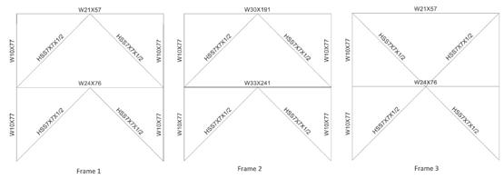
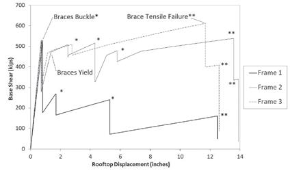
Concentrically braced frames (CBFs) resist large lateral forces due to wind and earthquake loading, and their ductility is largely derived from tension yielding and compressive buckling of the braces. Since 1990, AISC has focused on improving seismic resistance of CBFs by introducing detailing requirements for the connection, geometric limits of the brace, and capacity-designtype strength requirements for the gusset plate and the framing members. In 1997, a requirement was introduced that the strength of the beam in a frame with braces in a chevron configuration must be able to withstand the post-brace buckling unbalanced forces, based on the assumption that the braces in tension yield and the braces in compression resist 30% of their critical buckling loads (AISC 2010). However, many braced frames built prior to the mid-1990s do not meet this requirement and therefore are generally considered to be “weak” and substandard. A research project to address the performance and potential retrofit of these older braced frames is currently in progress. The article How Big is that Beam? (STRUCTURE magazine, November 2014) addresses this beam strength issue. The author analyzed three two-story frames using a nonlinear pushover analysis, shown in Figure 1a. The analyzed frames included a weak-beam chevron braced frame (Frame 1), a Structural strong-beam chevron braced frame (Frame 2), and a multi-story X-braced frame (Frame 3); the results are repeated in this article as Figure ForenSicS 1b. Frames 2 and 3 were found to perform adequately, but Frame 1 exhibited a significant loss in strength and stiffness after brace buckling. As seen in the Figures, the predicted response of each investigating structures and their components braced frame system is characterized by sudden drops in strength, which is not characteristic of braced frame tests with adequate connections. The 2014 article thereby concludes that a frame with an undersized beam results in poor frame performance. Further, the analysis suggested that Frame 2, with a strong beam and HSS braces meeting current AISC SCBF slenderness limits, may achieve an inelastic deformation of about 12 times the buckling deformation. The author did not provide dimensions for the frames reproduced in Figure 1a, but assuming a story height of 12 feet, this deformation corresponds to 4.0% to 4.8% average story drift. How Big is that Beam Revisited ? This assumed story height
(a) Frames From Prior Work
(b) Pushover Curves from Prior Work By Andrew D. Sen, Charles W. Roeder, Ph.D., Dawn E. Lehman, Ph.D. and Jeffrey W. Berman, Ph.D.
Andrew Sen is a doctoral student in structural engineering at the University of Washington. He can be reached at adsen@uw.edu. Charles Roeder, Ph.D., is a Professor of Civil Engineering at the University of Washington. He can be reached at croeder@u.washington.edu. Dawn Lehman, Ph.D., is a Professor of Civil and Environmental Engineering at the University of Washington. She can be reached at delehman@uw.edu. Jeffrey W. Berman, Ph.D., is the Thomas & Marilyn Nielsen Associate Professor in the Department of Civil and Environmental Engineering at University of Washington. He can be reached at jwberman@myuw.net.

aligns with dimensions common in practice and corresponds to approximately 0.3% average story drift at brace buckling, which is typical of braced frames in experiments. While the observations from these analyses are logical based on the results presented, this article contends those results are dependent on numerous assumptions that mischaracterize CBFs. The consequences of these assumptions are clear in the experimental results described below, which vary drastically from the results in the previous work. The authors have conducted tests that reflect the three categories of braced frames considered in the November article, and these experiments are discussed here. These tested frames include a chevron braced frame with a weak beam (left column of Figure 2), a chevron braced frame with a strong beam (center column of Figure 2; Sen 2014), and a multistory X-braced frame (right column of Figure 2; Lumpkin 2009). Figures 2b and 2c present the experimental cyclic and backbone curves of the three frames. The braces in all three frames were identical (HSS5×5×3/8). While the member sizes of these frames are different than those shown in Figure 1, the relative strengths of the various members are similar. The Figure 2. Comparison of Weak-Beam Chevron, Strong-Beam Chevron, and Multi-Story X Frames. frames were loaded quasistatically under a fully reversed increasing amplitude The curves in Figure 2b show that there ultimate strengths of the chevron braced cyclic protocol. The base shear is normalized by was little difference in the strength and frames were lower, although the multi-story the base shear force corresponding to buckling, stiffness of the weak- and strong-beam X frame had heavier columns, so some addiVbb. Equation 1 shows Vbb as a function of the chevron frames. This is not intuitive, tional strength would be expected. buckling capacity of the brace, Pcr, and the because the first story braces did not yield Another significant point of comparison brace angle, θ. in tension while the second story braces is that the weak-beam chevron frame had Vbb = 2Pcr cos θ Equation 1 did. However, frame action provided more lateral resistance on the first story than the approximately the same deformation capacity as the multi-story X frame prior to brace second story. The chevron braced frame is fracture. Deformation capacity is discussed an indeterminate system. While the truss in terms of drift range here, because local CADRE Pro 6 for Windows assumption is suitable for initial design, it cupping deformation at the brace mid-span Solves virtually any type of structure for is not valid for seismic evaluation due to in compression typically precipitates fracinternal loads, stresses, displacements, the complex inelastic behavior of CBFs. ture of the brace in tension; hence, both and natural modes. Easy to use modeling System capacity is dependent on the plastic directions of loading influence the ultimate tools including import from CAD. Much mechanism, which is incomplete in models response. The weak-beam chevron frame more than just FEA. Provides complete that neglect beam-to-column connection reached a story drift range of 4.12% prior structural validation with advanced features for stability, buckling, vibration, shock and seismic analyses. resistance and consequently lateral resistance due to frame action. This modeling to brace fracture; this is comparable to the maximum story drift range of the multisimplification is pronounced in a weak- story X-braced frame, which was 4.38%. CADRE Analytic beam frame, where the plastic mechanism Thus, the weak beam did not impact system Tel: 425-392-4309 is yielding of the beam and buckling of the drift capacity significantly. Finally, it must be www.cadreanalytic.com brace. For a strong-beam frame, the plastic noted that none of the HSS braces achieved mechanism is yielding of the brace in ten- the large story drifts predicted for Frames sion and buckling of the brace. Compared 1 and 2 in the prior work. HSS braces of to the multi-story X-braced frame, the this slenderness fracture at maximum story
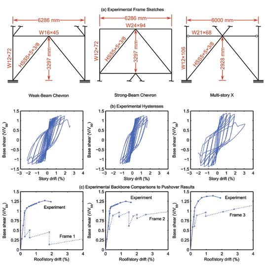
drifts in the order of 2.5%, with a maximum drift range of 4.5% to 5%. Th is has been documented in hundreds of prior tests (e.g., Tremblay 2002 and Fell et al. 2009). Other brace cross sections, such as wide fl anges, may achieve larger drift levels, but 4.0% average story drifts in tension are not achieved with HSS braces subjected to cyclic loading, as in earthquakes, since this implies much larger drift range (e.g., 8.0% if demand is balanced). Pushover analysis fails to capture the cyclic deterioration of the brace and is therefore unsuitable for predicting the deformation capacity of the system. A number of factors likely contribute to the discrepancies observed between the pushover analysis presented in the prior work and the experimental results described here. Braced frames are commonly modeled as trusses, but it is clear from the test results that considerable resistance is derived from moments and shear forces that develop in the beams and columns. Also, while neither the monotonic nor cyclic protocols represent real earthquake deformation demands, cyclic protocols simulate the load reversals that an earthquake may induce in a structure. Th is enables phenomena such as strain hardening and low-cycle fatigue to occur, which are important response characteristics. Finally, springs or concentrated hinges that are used in some nonlinear structural analysis software may not be suitable for capturing the material and geometric nonlinearities that develop in braced frames; fi ber-based or shell elements are required. Numerical results should always be interpreted with caution, and the limitations of software and input parameters (e.g., plastic hinge defi nitions) should not be overlooked. Much research still needs to be conducted to determine the viability of weak beams in older and modern chevron braced frames, but these preliminary results suggest that good performance may be achieved using shallower, lighter beams than permitted by the current Seismic Provisions. Th is is in stark contrast to the results of simplifi ed analyses of the How Big is Th at Beam? article, but the actual post-buckling behavior of braced frames is complex and diffi cult to capture without employing more robust analysis techniques.▪ Th is material is based upon work supported by the National Science Foundation Network for Earthquake Engineering Simulation under Grant No. CMMI-1208002, Collaborative Developments for Seismic Rehabilitation of Vulnerable Braced Frames and Graduate Research Fellowship under Grant No. DGE-1256082. Any opinion, fi ndings, and conclusions or recommendations expressed in this material are those of the authors and do not necessarily refl ect the views of the National Science Foundation. Additional support was also provided by the American Institute of Steel Construction in the form of steel donations.
Th e online version of this article contains detailed references. Please visit www.STRUCTUREmag.org.
Geopier is Ground improvement.®
The alternative to deep foundations.
Customized solutions for all soil types
Work with Geopier’s geotechnical engineers to solve your ground improvement challenges. Submit your project specifications to receive a customized feasibility assessment and preliminary cost estimate at geopier.com/feasibilityrequest.
800-371-7470 geopier.com info@geopier.com
©2015 Geopier Foundation Company, Inc. The Geopier® technology and brand names are protected under U.S. patents and trademarks listed at www.geopier.com/patents and other trademark applications and patents pending. Other foreign patents, patent applications, trademark registrations, and trademark applications also exist.
Integrating 3 Ds in 3D is Key to Project Success
By Mehdi Rashti, S.E.
Integrating 3D modeling software programs for the three “Ds” for this project – Ram for design, Revit for drafting and Tekla for detailing – proved to be the key for success for this fast track design-build project at a major Marine Corps base in California. The project consists of three adjoining structures, with very diverse functions, which form the new 131,000 square-foot Center for Naval Aviation Technical Training Complex (CNATT). The primary function of the complex is to house all aviation mechanics involved with the maintenance and repair of Huey and Cobra helicopters at the Marine Corps base at Camp Pendleton. This includes administrative activities, training, and the actual maintenance and repair of the helicopters in an open-bay hangar area. Aesthetically, one structure, rather than three, would have served the purpose. However, due to the diverse programming needs of each activity and structural system incompatibility, the team decided it was necessary to design three buildings so there could be seismic separations between them. The tall hangar building with a braced frame lateral load resisting system is one building (Figure 1); the four-story administration building with masonry shear walls is the second building; and a three-story classroom masonry shear wall building with an open space and column-free auditorium on the first floor is the third building. The team individually modeled and analyzed each building separately to manage the electronic file sizes. This also allowed several individuals to work on the same model at the same time through the work-sharing feature of Revit. The need to quickly double the size of its helicopter maintenance and repair training facilities was “mission critical” for the Marines in order to meet the rapidly growing demand for Huey and Cobra helicopters used in global combat operations. Therefore, the Marine Corps put the project on a fast track schedule and selected design-build as the
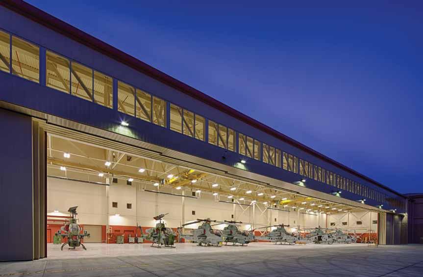
Figure 1. CNATT Helicopter Maintenance Hangar at night.
method of project delivery. The Corps also wanted the project to be a showcase design to reflect the vision of CNATT as “the preeminent leader in aviation maintenance training.” These goals presented significant challenges to the designers and builders. The accelerated schedule meant the team needed to start work immediately based on the parameters of the project outlined in the Request for Proposals (RFP). Another critical challenge was figuring out how to shorten the length of time required to fabricate a 320-foot span truss for the hangar building so the entire project could be designed and built within the allotted time frame. It also meant the design-build team had to resolve several potential problems during the planning and design phases of the project rather than address them later during the construction phase, as is normally the case. For instance, the team needed to overcome the problem of limited site access so that several heavy-duty cranes could be positioned to lift the hangar door truss. Another important issue to resolve involved the sequencing of field-assembled members for storage and erection.
Use of BIM
The team relied on 3D Building Information Modeling (BIM) software to help speed up the design timeframe and improve the quality control process. In order to achieve these goals, the team developed the following system. First, the engineers used the architectural Revit model to add structural members without any particular attention paid to the sizing of the members. The second step required them to export the Revit model to RAM/Risa for structural member sizing. Once they finished this task, the engineers then brought the analyzed model back to Revit for preparation of construction documents before finally exporting the documents to Tekla for steel detailing.
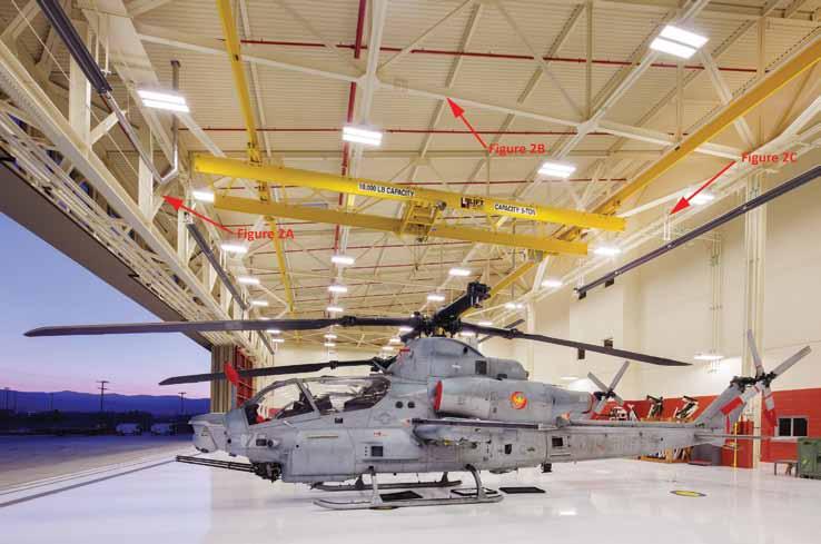
Figure 2. Helicopter Maintenance Hangar.
During the initial phase of the project, the structural team proposed a system of open web steel joists for the framing of the hangar roof system. As the work progressed, they realized they needed larger openings for the mechanical, electrical, and plumbing (MEP) lines to pass through the truss web members in the hangar building. This changed the direction of the hangar roof framing system from an open web steel joist type of truss to a custom-designed roof truss with fewer webbing members. Using Revit to model the actual truss member sizes and Tekla for the connection plates for the hangar roof truss connections allowed for detailed coordination among all the disciplines. Similarly, by modeling all of the masonry wall, roof, and floor-framing members in the administration and classroom buildings, it was possible to coordinate the exact location of MEP penetrations through the shear walls to avoid conflicts during construction. To facilitate this process, the team held weekly BIM coordination meetings among all the stakeholders, including the steel fabricator, to expedite the critical decision-making on the changes needed during the design work schedule. These meetings and coordination efforts saved money by avoiding conflicts between the various systems during construction. The result was the development of “No-Fly Zones” which are designated areas that are off-limits for contractors to position their pipes, duct, or other penetrations in the masonry shear walls in the administration and classroom buildings. Basically, the “No-Fly Zones” ensured that the inadvertent placement of unwanted holes or penetrations in critical sections of the walls would not affect the major components of the wall such as the chord bars, control joints, and beam pockets.
Design Challenges
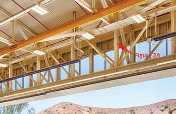
Hangar The anchor feature of the aviation training complex is a high-bay hangar space to house nine helicopters. The basic structural system design for the hangar portion of the building includes a corrugated metal roof deck spanning between steel purlins (Figure 2). Monoslope custom steel trusses (transverse trusses), spaced at 25-foot intervals, support the steel purlins (Figure 2b, page 33). A three-dimensional space truss at the front of the hangar, coupled with lattice-type “box” columns, support the header truss along the front of the hangar (Figure 2a). The 3D space truss, which is 10 feet wide and 16 feet deep, spans 320 feet along the front of the hangar, providing a clear, unobstructed entry for normal operations of helicopters. A single truss supported by individual columns provides support at the rear continued on page 33
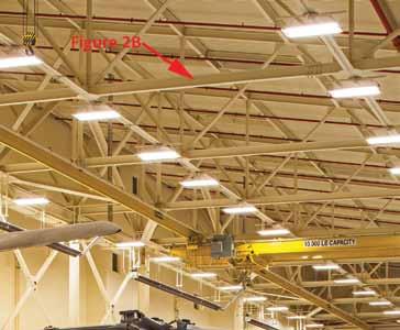
Figure 2b. Transverse truss. Figure 2c. Single-ply truss.
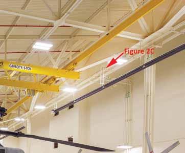
of the hangar (Figure 2c). The transverse trusses cantilever out 12 feet on the rear side of the hangar to reach the outline of the adjoining administration building and to provide enclosure between the two buildings. Masonry exterior walls enclose the hangar door pockets. A system of horizontal trusses in the plane of the bottom chord of the transverse trusses provides diaphragm action for distribution of lateral loads to the supporting brace frames. Two independent, 5-ton bridge cranes covering the entire hangar bay provide weight handling in the operation of the facility. Rail attachments to the bottom chord of the transverse trusses support these cranes. The hangar space required clear, unobstructed entry to allow for the normal operations of the helicopters. In order to accommodate a 29-foot clear hook height in the hangar bay, the structural engineers had to evaluate the ”box” truss for various shapes and sizes to minimize the tonnage. This was particularly challenging because they were dealing with very limited depth available for the “box” truss at the front of the hangar. The designers also analyzed the transverse trusses supporting the bridge crane rails, resulting in the addition of strategic strengthening members within the truss to limit the deflection to L/600 for proper operation of the crane rollers. The final design was a 320 foot-long span “box” truss with a weight of 250 tons. Administration Building Adjacent to the hangar building is a four-story reinforced concrete masonry administration building which forms one leg of the “L”-shaped structure. This building has a composite floor system, interior steel columns, and exterior bearing reinforced masonry shear walls. The second-floor elevation is 16 feet and the subsequent floorto-floor height is set at 14 feet. The biggest challenge for the design team for this building was to get natural lighting into the upper-level classrooms in order to meet the LEED natural day lighting requirements. This meant the team had to design the roof of the hangar and
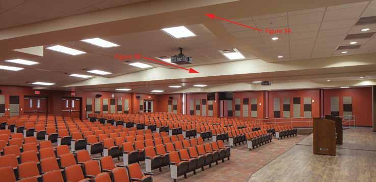
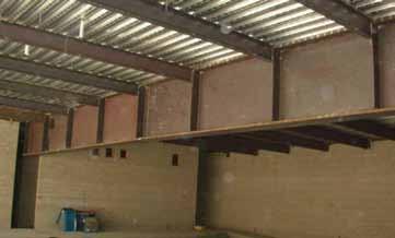
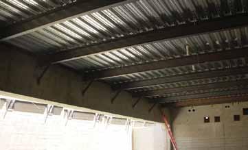
Figure 3a. Construction photo inset of 5-foot deep tapered steel girder. Figure 3b. Construction photo inset of 8-foot deep concrete transfer girder.
the height of the administration building in such a way as to allow for natural light to penetrate the upper-level classrooms. Classroom Building The classroom building, called The Applied Instructional Facility (AIF), forms the other leg of the “L” shaped building. It is separated from both the hangar and the administration building. The AIF building includes electronic classrooms for up to 400 students, aviation training shop laboratories, and a column-free auditorium at the first floor with a seating capacity of 250. Interior steel columns and the exterior masonry walls form the support of the structure at the upper levels. The interior steel columns and the exterior masonry walls terminate at the second floor to allow for a large column-free multi-purpose auditorium (Figure 3). In order to transfer loads, the engineers designed an 8-foot deep concrete transfer girder spanning 80 feet for the support of the 3-story exterior masonry wall above the auditorium (Figure 3b) and a 5-foot deep tapered steel girder to support the upper level interior steel columns (Figure 3a). The designers limited the deflection of the concrete and steel girders to L/600 to avoid cracking in the masonry walls and excessive defection in the steel girder. Holes in the 5-foot deep tapered steel girder accommodated passage of the utilities from one side of the auditorium to the other.
Steel Fabrication and Construction
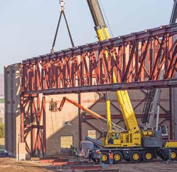
The designers, contractors, and fabricators needed to make an important decision about the means and methods of construction because they were dealing with two difficult field issues. The first challenge involved access to the site, which was very limited. The second challenge involved the difficulty of positioning the cranes required to lift the main entry “box” truss of the hangar. In the end, the team decided it was more desirable to field-bolt the box truss rather than shop-weld it, because field-bolting would provide more flexibility for fabrication of smaller pieces and assembly in the field. To achieve some level of economy, the smaller transverse trusses were fabricated into two pieces in the shop and field assembled into a single truss in the field, and then lifted into position as a single piece oneby-one using a single 200-ton crane (Figure 4). For the box truss, the fabricator shop-welded connections for the top and bottom “ladder” chords into five segments. These chord segments, as well as all the webbing members, were field-bolted for the entire truss assembly to be put together and lifted into position using two 200-ton cranes. The decision to design and build the entire truss on site enabled the team to trim nearly 12 weeks from the original design/construction schedule.
Conclusion
The design and construction process is constantly evolving. 3D modeling available through BIM has only been around for a few years. In a few more years, designers and builders most likely will simultaneously access cloud-based information in real time. At this point in time, however, the most valuable lesson learned by this structural engineering team is a time-honored, practical lesson. And that is, the best way to avoid any field coordination problems during construction is to identify and deal with critical design and construction issues immediately at project start.▪
Mehdi Rashti, S.E., is the Chief Executive Officer and founding principal of the SMR Consulting Group in San Diego, CA, the parent company of SMR-ISD Consulting Structural Engineers, Inc. He is a member of the Structural Engineers Association of California (SEAOC).



OPTIMIZE


Your Design Solutions for Light-Framed Multi-Story Construction

Seismic and wind events pose serious threats to the structural integrity and safety of structures. Building structures with a continuous load path can mean the difference between withstanding these types of natural disasters – or not.
All wood-framed buildings need to be designed to resist shearwall overturning and roof-uplift forces. For one- and two-story structures, structural connectors (straps, hurricane ties and holdowns) have been the traditional answer. With the growth in light-frame, multi-story wood structures, however, rod systems have become an increasingly popular load-restraint solution.
Simpson Strong-Tie® Strong-Rod™ continuous rod tiedown systems are designed to restrain both lateral and uplift loads, while maintaining reasonable costs on material and labor. Our continuous rod tiedown systems include the Anchor Tiedown System for shearwall overturning restraint (Strong-Rod™ ATS) and the Uplift Restraint System for roofs (Strong-Rod™ URS).
Strong-Rod ATS for Overturning
Strong-Rod ATS solutions address the many design factors that need to be considered to ensure proper performance against shearwall overturning, such as rod elongation, wood shrinkage, construction settling, shrinkage compensating device deflection, incremental loads, cumulative tension loads, and anchorage.
Strong-Rod URS for Uplift
Strong-Rod URS solutions address the many design factors that need to be considered to ensure proper performance against roof uplift, such as rod elongation, wood shrinkage, rod-run spacing, wood top-plate design (connection to roof framing, reinforcement at splices, bending and rotation restraint), and anchorage.
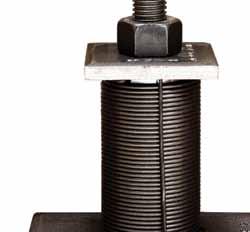
Strong-Rod Systems have been extensively tested by engineers at our state-of-the-art, accredited labs. Our testing and expertise are crucial in providing customers with code-listed solutions. The Strong-Rod URS solution is code-listed in evaluation report ICC-ES ESR-1161 in accordance with AC391, while the take-up devices used in both the ATS and URS solutions are code-listed in evaluation report ICC-ES ESR-2320 in accordance with AC316.
Because no two buildings are alike, Simpson Strong-Tie offers many design methods using code-listed components and systems to help you meet your complex design challenges.
Let us help you optimize your designs. For more information about our Strong-Rod™ systems continuous rod tiedown solutions or traditional connector solutions, call (800) 999-5099 and download our new Strong-Rod™ Systems Design Guide at strongtie.com/srs.


