27 minute read
Structural Testing
issues and advances related to structural testing Owners and designers may find themselves confronted with the task of deciding what to do with an existing masonry building, particularly if there will be a change of use or modifications to the structural system. Part of that decision should include determination of whether the structural system is adequate in its current condition for the building’s intended use, whether minor or extensive repair and retrofit measures are required, or whether the building has deteriorated to a state that it is beyond its usable life. Nondestructive and minimally invasive diagnostic techniques play a vital role in determining properties of existing masonry construction without causing excessive disturbance or disruption to the building fabric. This article discusses the different methods available for identifying masonry distress conditions and evaluating engineering properties such as strength and stiffness.
Material Evaluating Existing Properties Masonry Construction The masonry material properties needed by the engineer will ultimately depend on the role of Nondestructive and masonry in the overall structural system, but may include compressive strength, shear strength, In-Situ Methods presence and extent of voids, existence and condition of reinforcing, and even moisture resistance. By Andrew Geister, P.E. The use of destructive techniques may be undesirable due to the cost, damage and potential structural instability resulting from creating large openings or removal of several material samples. Fortunately, many nondestructive and in-situ methods exist, several of which have standardAndrew Geister, P.E. has been involved in masonry nondestructive, in-situ, and laboratory material testing while working for AtkinsonNoland & Associates, Inc. in Boulder, Colorado. He is also a member of The Masonry Society’s Existing Masonry Committee and Design Practices Committee. Andrew can be reached at ageister@ana-usa.com. ized procedures to determine necessary material properties without causing undue damage to the structure. The keys to establishing a successful masonry testing program include determining which material properties are critical to the building’s intended use, as well as selecting an appropriate number of tests and test locations. For reinforced masonry, quantifying the presence of voids in grout, and location of reinforcing are likely to be some of the most important properties. For unreinforced masonry, particularly in historic construction, determination of compressive strength, elastic modulus, and shear strength is especially important in order to take advantage of these inherent material properties in design. In situations where variable construction or workmanship are encountered or suspected, additional testing can also help determine appropriate design values for different construction phases or parts of the building. For nonstructural masonry such as veneers, the focus will more likely be
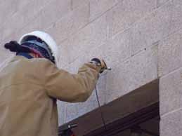
Figure 1: Using a fiber optic borescope inserted into a drilled hole in a mortar joint to view the inside of a concrete masonry lintel.
on connections to the structural system, moisture management, and energy issues rather than strength properties.
Nondestructive Techniques
Voids and Reinforcing When investigating how solidly an existing masonry wall was built, simply tapping with a sounding hammer may be sufficient to determine if CMU cells are grouted or empty. For smaller voids and cracks in thicker, multi-wythe walls, more sophisticated techniques and equipment may be needed. Ultrasonic methods, such as pulse velocity which measures the transit time of stress waves between transducers, or impact-echo which measures the stress wave reflections from discontinuities in the structure, are both good tools for assessing the extent of internal cracks and voids. These types of irregularities can also be observed visually through the use of a fiber optic borescope inserted into an existing opening or small diameter drilled hole within a mortar joint (Figures 1 and 2). This method is also useful in cavity wall construction for observing veneer ties or excess mortar inside the wall cavity. Somewhat larger scale voids can be detected through the use of Surface Penetrating Radar (SPR) which locates material differences indicated by reflected microwave energy, and Infrared Thermography (IRT)
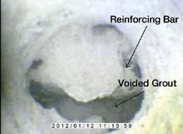
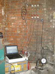
Figure 3: Masonry deformability test by the Flatjack method to estimate masonry compressive strength and elastic modulus. Both Flatjacks are pressurized while monitoring surface strain to generate an in-place stress-strain curve. throughout the structure. Half-cell testing, however, has been used successfully to determine the potential for metal corrosion in reinforced masonry at locations that are electrically connected to the exposed bar, such as along a single vertical reinforced cell or along a bond beam. Masonry Strength and Stiffness An estimate of masonry compressive strength and elastic modulus is determined through the use of Flatjacks following the standard test method of ASTM C1197. Flatjacks are thin hydraulic bladders inserted into slots cut in masonry bed joints, and pressurized to perform an in-situ compressive strength test while monitoring the surface strain of the masonry between Flatjacks to generate a stress-strain curve (Figure 3). Although this method requires sawcutting two slots in the mortar joints to insert the Flatjacks, it is much less destructive than the removal of masonry prisms, which may be damaged during sampling or transport. If the current stress state of the masonry is desired at a particular location, the single
which is capable of detecting temperature diff erences between the solid masonry materials and voided air spaces. Th e existence of metal reinforcing bars, steel sections, or even pipes and conduit may be detected using SPR, relying on the highly refl ective nature of metal objects to the transmitted radar energy. Other types of metal-detection devices such as a pachometer are also useful for locating veneer ties, joint reinforcing, and reinforcing bars that are located near the wall surface. Once the reinforcing is located, information about its size or quality may be desired. If a small opening exists or can be made to expose a portion of the metal reinforcing, its thickness can be measured using an ultrasonic thickness gauge without having to uncover the entire bar to take a physical measurement. Th e device transmits a sound signal into the exposed surface of the metal, and measures the amount of time required for the sound to travel through the material and its echo to refl ect back to the surface. Half-cell testing measures the potential for corrosion of metal reinforcing by fi rst connecting a wire from the device to a small exposed portion of reinforcing, and then surface measurements are made throughout the structure. Th is method has been used more commonly in reinforced concrete structures containing mats of reinforcing bars that are in contact or close proximity with one another, and thus has been able to provide good electrical continuity
Star Seismic BRBs land bigger projects
It’s no fish story. Contact Star Seismic to see how we can help you land your next trophy project.
Call: 435.940.9222
www.starseismic.net
Figure 4: Infrared thermograhpy image showing areas of rising damp and path of moisture travel.
Flatjack method of ASTM C1196 provides a means to measure this property. First, the stress is relieved by cutting a horizontal slot in the bed joint, which also causes the masonry above to deform slightly. The Flatjack is then inserted and pressurized, and the pressure is measured as the masonry above is restored to its original position. Similarly, masonry mortar joint shear strength may be measured using the standard test method of ASTM C1531, which utilizes a single specially sized Flatjack, also known as a “Shearjack,” to fit within a head joint, which is pressurized until it moves the adjacent brick unit sideways into the opposite, previously opened head joint. Mortar Qualities If there are concerns about the quality or uniformity of the mortar used in the existing construction, mortar quality and consistency throughout the building may be evaluated and compared using a rebound hammer, which measures the amount of rebound of a pendulum weight after striking the mortar surface, similar to the use of a Schmidt hammer device used for testing concrete surface hardness. In addition to surface hardness, knowledge of the mortar characteristics deeper inside the wall may be needed, such as in situations where past repairs or repointing have covered the original mortar with a different type of material. Resistance drilling techniques have been reported to produce good correlation with mortar compressive strength values, and only require small holes drilled in existing mortar joints. Moisture Management Moisture problems can be one of the biggest threats to both structural masonry and veneer systems. Although masonry is generally a very durable material, exposure to excessive amounts of moisture can lead to unsightly efflorescence, plant growth, and premature deterioration. In climates that produce freezing temperatures, especially those with many cycles of freezing and thawing, deterioration can occur more quickly if masonry remains saturated. Keep in mind, when investigating masonry moisture issues, that both the source of the moisture and the water penetration properties of the masonry are important. When weather conditions permit, IRT is useful for locating moisture paths and damp areas (Figure 4). Many types of electric capacitance-based moisture meters and resistance-based probes are available for detection of wet areas and are useful for tracing the moisture path to its source. The rate of moisture penetration through masonry walls is determined using the standard test method of ASTM C1601. The standard test chamber mounted to the masonry surface applies water and pressure, creating conditions that simulate wind-driven rain (Figure 5). The rate of water loss from the chamber into the masonry is measured, and is used to determine its water penetration resistance. Visual observations of the opposite wall face during the test can also give useful information about the path the moisture takes as it travels through the wall. A very fast and simple method for measuring water movement through a masonry surface is the water absorption tube test given by RILEM method II.4. RILEM (English translation from French: International Union of Laboratories and Experts in Construction Materials, Systems, and Structures) is an international technical organization which develops standards for testing materials and structures, similar to ASTM in the United States. Different tube sizes are available, but the configuration consists of a circular opening perpendicular to a vertical graduated tube. The opening is attached to the masonry surface and the graduated tube portion of the tube is filled
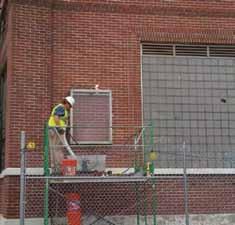
Figure 5: Moisture penetration testing for masonry walls using ASTM C1601 water chamber.
with water, resulting in a pressure head being applied to the masonry surface. This type of testing is attractive because many tests can be performed quickly, and is useful for getting an impression of masonry absorption, or for comparing water repellent treatments.
Quality & Performance
Quality Control A successful construction or repair project depends on the quality of work performed being as good as it was designed and specified to be. Nondestructive methods such as SPR and IRT are especially useful to determine the effectiveness of repairs such as rebuilding or injection, especially when a “before and after” comparison can be made with the results. Metal detection methods are also helpful for confirming the placement of retrofit anchors or veneer ties without visual observation. The costs associated with these methods
Material Characteristics Test Method Compressive strength, elastic modulus Flatjack (ASTM C1197) In-situ stress Flatjack (ASTM C1196) Shear strength Flatjack “Shearjack” (ASTM C1531)
Voids
Surface Penetrating Radar, Infrared Thermography, Borescope, Sounding, Pulse Velocity Cracks Impact echo, Pulse velocity (ASTM C597) Reinforcing and metal objects Surface Penetrating Radar, Pachometer Reinforcing condition Borescope, Ultrasonic thickness gauge, Half-cell potential (ASTM C876) Mortar consistency & quality Rebound hammer, Resistance drill Moisture penetration Spray chamber (ASTM C1601), IRT, Water tube (RILEM II.4) Crack width & building movement Structural monitoring
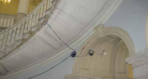
Figure 6: Vibrating wire crack monitors used for long-term structural movement monitoring.
are likely to be lower than providing full-time inspections, or opening completed repairs for observation and repeating the repair work. Structural Monitoring A good monitoring program can provide peace of mind before, during, and after repairs are conducted. Before deciding which repairs are necessary, structural monitoring can help determine if cracks are active or dormant, and if the building is moving, whether the movement is due to natural weather cycles or something more serious. Monitoring systems that operate on vibrating wire technology feature a central datalogger connected to sensors that are capable of measuring crack width, tilt angle, surface strain, and temperature. Th e system itself requires only a low power input, so extended longevity is possible with little maintenance. Th ese monitoring systems can be installed using adhesives or small anchors, so the impact to the structure is minimal (Figure
ADVERTISEMENT - For Advertiser Information, visit www.STRUCTUREmag.org 6). During construction, monitoring is useful to determine if the ongoing activity is causing additional building distress or movement. Th e activity does not necessarily need to originate from your site to aff ect your structure, either. An adjacent excavation or heavy equipment can aff ect your building as well. After repairs, strengthening, or stabilization work have been completed, a long term structural monitoring program will result in valuable data that will aid in diagnosing future distress, aid in detecting potential problems before they become serious and more expensive to fi x and, fi nally, ease concerns about long term structural performance.
Conclusions
A variety of nondestructive and in-situ methods exist to determine material properties and to diagnose problems in existing masonry structures without the need for sample removal. Th e information gained from a testing program that is well-planned and performed correctly, with results interpreted by experienced professionals, can reduce costly repairs to the concentrated areas where they are needed, and can provide design engineers with confi dence about the materials they are working with on any given project.▪
Crossed Arches Pipe Bridge

By Wayne A. Bamossy, P.E., M. ASCE, Jennifer A. Barrick, P.E. and William W. Lai, P.E.
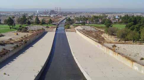
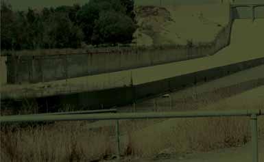
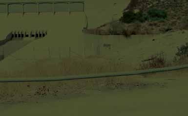
Spillgates of the Hansen Dam, source of the Tujunga Channel, upstream of the crossed arches pipe bridge.
Mies van der Rohe’s famous maxim, “Less is more,” clearly applies to the pipe bridge recently built across the Tujunga Channel in the Lake View Terrace area of Los Angeles to supply recycled water to the Hansen Dam Municipal Golf Course. Overall simplicity and sparing use of material contribute to what strikes many as an elegant appearance. e bridge is part of the Hansen Dam Golf Course Water Recycling Project of the Los Angeles Department of Water and Power (LADWP). e Hansen Dam Municipal Golf Course will soon join several other golf courses, cemeteries, parks, and nurseries in the LADWP service area that use recycled water for irrigation of large areas of turf or other landscaping. e view of the pipe and bridge also illustrates why LADWP sta often refer to recycled water projects as “purple pipe projects”.
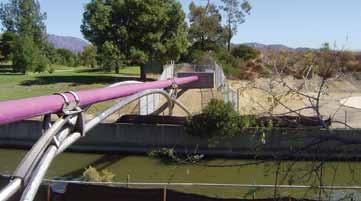
View of the completed crossed arches pipe bridge.
Bridge Design
Owned by the United States Army Corps of Engineers (USACE), the Tujunga Channel conveys storm water out of the Hansen Flood Control Basin to nearby spreading grounds that recharge the San Fernando Groundwater Basin or on further to the Los Angeles River. e Los Angeles County Flood Control Districts (LACFCD) also regulate work within the channel right-of-way. ese two agencies established a number of design goals and requirements for the pipe and bridge. • easement for the pipe and bridge as narrow as possible • minimal surcharge to the channel walls from the bridge footings
• shortest possible construction duration • strong preference that no construction equipment enter the channel • requirement for twelve foot vertical clearance to the channel e Hansen Dam Municipal Golf Course is on USACE-owned land leased to the City of Los Angeles Department of Recreation and Parks. Golf course management requested a low pro le for the bridge and pipeline. e design also was shaped by the LADWP Water Distribution Division’s desire for low maintenance and long service life of the bridge and pipeline. Bridge designer William W. Lai, P.E., of LADWP’s Civil & Structural Design Group, came up with the novel concept of crossed arches after wrestling with the problem of how to provide resistance to lateral loads, including seismic. Instead of inserting braces between the arches, crossing the arches provided an e cient way to resist lateral forces. e use of arches allowed the design of drilled pier foundations that t within the narrow right-of-way available. e decision to use pipe for the arches stemmed from a desire to use type 316 stainless steel throughout the bridge structure to prevent corrosion. e number of structural shapes available in stainless steel is limited, but pipe is readily available. Pipe is also more easily bent to radius compared to some other structural shapes. e Tujunga Channel is 60 feet wide at the bridge crossing. e bridge span is about 82 feet. e bridge carries a 128-foot length of epoxy-coated 20-inch diameter welded steel pipe which weighs about 28 kips when lled with recycled water. Concrete thrust blocks are provided at each end of the water pipe where it bends down 45 degrees to join the buried ductile iron pipeline. e geometric layout of the bridge arches was calculated using analytical geometry formulae in an Excel spreadsheet. Stress analysis was performed with RISA 3D software. Stress levels in the stainless steel were limited to about 60 percent of the values allowed for carbon ree bridges crossing the Tujunga Channel: golf cart bridge, crossed arches pipe bridge, and rubber dam maintenance bridge. Red and white stacks in background are at Valley Generating Station, site of the steel. e governing load was full dead load, which produced mostly compressive forces recycled water Hansen Tank and Pumping Station. with some bending. None of the structural
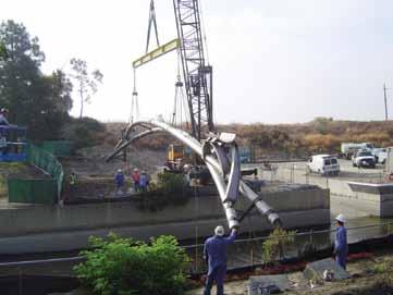
American 7150 Mobile Crane hoists completely assembled crossed arches pipe bridge into position.
Bridge Fabrication
All fabrication, except rolling the pipe arches to radius, was by the LADWP’s Structural Steel Shop. e 10-inch diameter pipes were rolled to a radius of 86 feet by Marine Valve and Supply Co. of Whittier, California. e bridge, including the chairs, was completely assembled and welded in the shop, except for the mid-span welds. e shop designed and fabricated temporary supports and braces to keep the bridge arches properly positioned, and LADWP surveyors veri ed that the alignment was correct.
capacity of the welded steel water pipe was considered in design; all loads were assumed to be carried by the arches. Seismic forces induced cyclic load reversal resulting in tension and compression; torsion and bending stresses were minor. e crossed arches were designed from 10-inch diameter pipe with full penetration butt welds and pinned end connections. Pin-like connections were also designed for the two crossing points. e two connecting structures from the arches to the recycled water pipe, dubbed “the chairs”, each have four legs supporting half-cylinder pipe seats with clamp straps over the top of the pipe. Each leg is an H-shape with 6-inch anges and a web tapering from 14¼ inches to 3½ inches. e chairs were fabricated by cutting, rolling, and then welding ¼-inch plate. e chair legs are tapered from their bases on the arches to the seats for the water pipe, and the weak axis of the section follows a curved path. e chair legs see moment at their bases and axial force along their length. e seats are lined with neoprene to help prevent galvanic corrosion between the water pipe and the chairs, and also to shield the water pipe from excessive vibration and contact stress. e two chairs and two end thrust blocks divide the water pipe into spans of approximately 37 feet, 54 feet, and 37 feet. e total bridge steel weight is about 12 kips. e design was modeled and turned into drawings using AutoDesk REVIT Structure software. is approach worked so well that shop drawings were not necessary and all model dimensions were within ⅛ inch of the drawing dimensions. Yousef A. Gobran, P.E., of LADWP’s Geotechnical Engineering Group, designed four reinforced concrete drilled pier foundations topped with rectangular pile caps sloped at a 45 degree angle. Each drilled pier is 36 inches in diameter and 21 feet deep, and resists the applied loads by skin friction. The out-to-out width of the bridge and foundations is only ten feet. Jianping Hu, Ph.D., P.E., G.E., also of the Geotechnical Engineering Group, used Sigma/W 2004 software to provide the USACE with a finite element method soil stress analysis to demonstrate that forces transmitted to the walls of the Tujunga Channel from the piers were within acceptable limits.
Bridge Construction
LADWP’s Integrated Support Services Division (ISS) built the foundations, erected the bridge, and installed the recycled water pipe and thrust blocks. Each arch was trucked to the site in two pieces. ey were then attached to the same temporary supports and braces used during assembly in the shop, surveyed again, and the nal center-span welds were made in the eld. e completely assembled bridge and the temporary braces were then hoisted into place across the Tujunga Channel with a mobile crane. No equipment entered the channel, as requested by the Regional Water Quality Control Board. e value of prior shop assembly and surveying was con rmed when the bridge was placed and fastened to the foundations on the rst attempt. A dual baseplate system was used. One set of baseplates, including leveling nuts, was attached to the anchor bolts on the piers. A second set of baseplates with brackets was pinned to the ends of the arches and then eld welded to the rst set of baseplates. Once the baseplates were welded, the temporary braces were removed. en the water pipe was installed on top of the bridge, followed by construction of the reinforced concrete thrust blocks at the ends. continued on next page
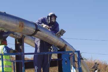
Temporary plates, braces, and supports help to t up the mid-span weld of the crossed arches pipe bridge.

Site preparation and foundation work for the bridge began in March 2011. e pipe bridge superstructure was erected and the recycled water pipe was placed on it in August and September 2011. Construction of the ductile iron pipeline began in September 2012 by LADWP’s Water Distribution Division. Construction of the pumping station by ISS will begin in March 2013. e initial purpose of the project is to deliver about 500 acre-feet per year of recycled water for irrigation of the Hansen Dam Municipal Golf Course. However, the pipeline and pumping station were sized anticipating customers in addition to the golf course.
Project Credits
Project Owner, Engineer, and Constructor: LADWP Fabrication: LADWP Structural Steel Shop Pipe Bending: Marine Valve and Supply Co., Whittier, CA Bridge and Pumping Station Construction: LADWP Integrated
Support Services Division Pipeline Construction: LADWP Water Distribution Division
Conclusion
Bridge designer, William Lai, believes that the design concept for the small crossed arches pipe bridge over the Tujunga Channel can be scaled up for longer spans and heavier loads. He also believes that the concept could be adapted to loads other than pipe, e.g., a road deck. Until recently, the authors were unaware of other examples of bridges with crossed arches. e December 2012 issue of STRUCTURE magazine features the award-winning Tempe (Arizona) Town Lake Pedestrian Bridge, designed by T.Y. Lin International, which prominently utilizes crossed arches to support the pedestrian deck.▪ Wayne A. Bamossy, P.E., M. ASCE is the Manager of Construction Management Group, Los Angeles Department of Water and Power. He may be reached at Wayne.Bamossy@Ladwp.com. Jennifer A. Barrick, P.E. is a Project Manager at the Los Angeles Department of Water and Power. She may be reached at Jennifer.Barrick@Ladwp.com. William W. Lai, P.E. is a Bridge Design Manager at the Los Angeles Department of Water and Power. He may be reached at William.Lai@Ladwp.com.
ADVERTISEMENT–For Advertiser Information, visit www.STRUCTUREmag.org


Structural Software Designed for Your Success

Easy to Learn and Use Analyze “Just about Anything!” Design: Steel, Wood, Concrete, Aluminum, and Cold-Formed
www.iesweb.com
Free 30-Day Trial

IES, Inc. | 519 E Babcock St. Bozeman MT 59715 800-707-0816 | info@iesweb.com


Modeling and Analysis of a Masonry Building on Piling
By Louis Scatena, P.E.
This article summarizes the development of a structural model to analyze and design a concrete masonry building that includes a structural steel roof and concrete mat foundation supported on concrete grade beams and drilled concrete piles (caissons). The building (Figure 1) will enclose large electrical equipment at a water treatment facility that is near a major seismic fault in northern California. The design was completed by the office of Carollo Engineers in Walnut Creek, California, and the author developed the model and conducted analyses using Bentley Systems STAADPro software.
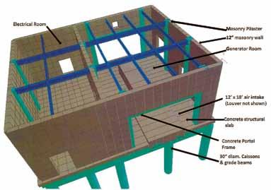
Figure 1: Structural rendering of generator building with roof deck removed.
Design Challenges
The project included seismic design considerations that, taken collectively, made modeling the otherwise unimposing Generator Building somewhat unusual, including: 1) Proximity to the San Andreas Fault system in northern California; 2) Large louvered openings in masonry shear walls for air intake and exhaust; 3) Concrete caissons threaded in an unsymmetrical pattern between numerous existing buried utilities; 4) A complex array of vertical and horizontal soil springs surrounding the mat foundation and concrete grade beams; 5) Separate soil springs for caissons penetrating layers of disturbed soil and embedded in fractured shale; 6) Latest code requirements for analysis of accidental torsion, amplified torsional effects, and orthogonal earthquake load combinations for rigid diaphragms; 7) Substantial concern for accurate determination of seismic effects at steel beam to masonry wall connections that have limited ductility, under a multitude of load combinations. Instead, a concrete slab was assumed with material characteristics that allowed the model to replicate the stiffness and strength of the actual concrete-topped steel deck as specified on the design drawings. Three trials led to the selection of density, elastic modulus, shear modulus, and Poisson’s ratio for the concrete deck to replicate the diaphragm stiffness that was previously calculated using the flexibility factors documented in the International Code Council Evaluation Report for the deck. Design codes specify that “cracked” masonry and concrete should be assumed in the seismic design. Based on ACI 318 Sect. 8.7 and ACI 530 Sect. 1.9 commentary, this requirement for reduced stiffness was achieved by reducing the moduli of elasticity and shear, and using the corresponding Poisson’s ratio. Masonry design codes report a broad range of values for these moduli, and mid-range values were selected for a fully grouted and reinforced wall with pilasters.
Geotechnical Requirements and Software Issues
The geotechnical consultant provided vertical capacities for the 30-inch-diameter caissons and indicated that the shafts would need to extend 8 feet to bedrock, and 5 to 10 feet into the fractured shale.
Model Setup and Material Selection
The model setup was primarily accomplished using the software’s graphical user interface, occasionally in combination with the text editor. Roof deck, masonry walls and concrete mat were modeled as plates two feet square. Structural steel roof purlins and girders were assumed initially, and the program selected them during the final analysis based on AISC design parameters. Dimensions for masonry wall pilasters, concrete grade beams, and caissons were initially assumed as well. Concrete portal frames were placed around the large louvered openings in the east and west bearing walls. Building dimensions were frequently revised during the early design stages by other engineering disciplines. It was relatively easy to keep pace with these model changes by selecting the entire geometry for the affected portion of the structure and then moving it. The author selected 1½-inch deep steel roof deck with 5¼-inch reinforced concrete topping and, based on experience, decided that the beam sizes would be relatively light and not of the magnitude that would economically justify activating the available beam/deck composite design tools.
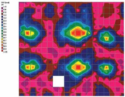

Figure 3: West wall maximum north-south seismic shear.
Soil improvement was not feasible due to the multitude of existing buried utilities. The consultant provided stiffness values for horizontal and vertical “soil springs” for the mat, caissons, and grade beams, which were modeled initially as “compression only” springs. During insertion of the horizontal springs at grade beams, it became apparent that these springs would override the vertical springs that had been previously assigned to the same nodes for the slab. With the assistance of Bentley Technical Support, the author determined that the springs could be reinstated by inserting the spring values in the text editor instead of the graphical interface. Bentley indicated that this anomaly would be resolved in the next release of the software. The soil springs also resulted in a few “instability warnings” during initial analyses. Again with assistance from Bentley Technical Support, the author determined that these “warnings” could be eliminated if the “compression only” assignments were removed from support specifications prior to the primary load case listing, and re-inserted as “changed supports” in the text editor immediately prior to the list of load combinations.
Benefits of the Model
The structural model facilitated many aspects of the design process, including:
A. Heavy equipment is suspended from the roof beams, and seismic effects on the diaphragm could be accurately assessed (Figure 2).
B. The code required measurement of drift in multiple locations. Model analysis made it possible to quantify values at any location under all load cases.
C. It was not difficult to measure stresses around large openings in shear walls (Figure 3)
D. Precise stress patterns in the software’s post-processor enhanced economical placement of reinforcing (Figure 4).
E. It was possible to evaluate reactions for caissons under any load combination, and confirm adequate resistance to lateral loads and uplift.
F. Post-processing confirmed that masonry “breakout” stresses at steel beam and strut connections were within allowable values. Slip connections were provided where wall restraint would otherwise be inadequate.
Seismic Permutations
Model analysis enabled the project design to meet the relatively complex seismic requirements of ASCE 7-05 and the California Building Code. Accurate analysis of the caissons between existing utilities presented a unique challenge because the caissons were shallow and
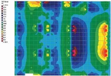
Figure 4: Maximum shear stress in ground floor slab.
non-symmetrically placed. Also, reliable assessment of potential uplift and horizontal soil support was mandatory. To address this challenge, the author used the system of “Seismic Permutations” documented in the STAADPro technical reference documents. More than 40 load cases were employed to assess torsional and extreme torsional irregularity; implement code requirements for redundancy, accidental eccentricities, and amplified torsional effects; and combine effects orthogonally. For the Generator Building, the task became easier when permutations were copied from a template that had been developed, improved, and updated iteratively during prior projects; pasted in the new project’s text editor; and re-factored for the requirements of the new structure. For example, model analyses concluded that torsional irregularity did not exist in the X-direction, but did exist in the Z-direction, and accidental loading in that direction also had to be amplified. Extreme torsional irregularity was shown to be non- existent in either direction. Code requirements also dictated that a redundancy factor of 1.3 had to be applied for load combinations in the Z-direction.
Conclusion
Understandably, some structural engineers could argue that the time spent in setting up a computer model is not always justified, nor is precise analysis always required. However, on many projects, time spent on this task – especially after reusable templates have been developed on prior projects – could amount to less time than would be spent using conventional spreadsheets, and final results could provide the project owner with greater value. Nevertheless, many initial templates can be like “black boxes” and checking with conventional spreadsheets (as done on this project) is essential. The population in the South San Francisco area will rely on the Generator Building and its equipment to provide power and water during earthquakes that are not uncommon to the region. Modeling and analysis provided assurance that the source of this service will be sustained, even in the event of an extreme emergency. Comparable modeling efforts may be indispensable as seismic requirements and design codes continue to grow in magnitude and complexity.▪
Louis Scatena, P.E. (LScatena@carollo.com), is a senior structural engineer with Carollo Engineers, Inc. He has 25 years of experience in the design of public buildings and water treatment facilities in the United States.


