47 minute read
gustav lindenthal’s little Hell gate rail Bridge


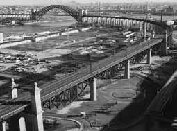
Near the flagship Hell Gate Bridge (STRUCTURE, October 2013), and crossing a former inlet between Wards and Randalls Islands, stands Gustav Lindenthal’s still-in-service 1915 Little Hell Gate Bridge; four unique skewed-deck truss spans of reverse parabolic bowstring arches. They are visually striking, sited as they are above flat land and below miles of high plate-girder viaducts. The total length between centers of the abutments is 1153.5 feet. Four-rail tracks operate on the 60-foot wide deck (Figure 1). The War Department at that time regulated waterways and, as this arm of the East River was only a few feet deep and would not carry maritime traffic, it granted approvals in 1906 and 1912 for piers in the inlet and the use of falsework for the construction. Later, landfill from the Triborough Bridge project (Ammann, 1937) entirely filled the inlet.
Timber and Masonry for the Piers
The Portland cement concrete piers bear at four tons per square foot on foundations of hard strata, typically mica schist, encountered at a shallow depth of about 12-15 feet below mean low water. Henry Seaman, consulting engineer for the masonry on the project, described the process of the foundation and pier construction. Executed by the McClintic-Marshall Construction Company, piles were first driven into the river bottom to support the timber falsework of square posts and longitudinal bracing members. Next, for the piers near Little Hell Gate, heavy-timber crib open-cofferdams were built, and the area within leveled and dried. Concrete for the foundation of the piers was poured into forms set within the dams. Granite veneer covers the 12 vertical feet between mean high and low tide levels to protect the concrete piers from wear due to rapid current. The timber for the trestle, posts, and longitudinal bracing of the falsework was longleaf yellow pine. And a great deal of it. The project used 360,000 board feet of heavy timber for falsework construction for each span. In discussions after completion of the project, some engineers suggested that floating the truss arches into place might have been more economical and efficient.
Figure 1. Flanked by viaduct spans, the century-old, still in service, distinctive Little Hell Gate Bridge reverse bowstring arch-spans suspend; with the Hell Gate and Triborough Bridges beyond. HAER NY 12116, Weinstein, Photographer, 1996.
Figure 2. Lindenthal office drawing, Little Hell Gate Bridge, plan and elevation. The center skewed piers originally aligned with the inlet current. Two tracks load each truss. Transactions of ASCE, v. 82: 1918.
Historic structures
significant structures of the past
Formwork consisted of two-inch thick, shiplap timber sheeting under four by eight-inch studs, held with wales and then bolted end-toend for tensioning against leakage. The river pier shaft forms were barrel-hooped. On Randalls Island, concrete was mixed on-site in a hopper below ground Gustav Lindenthal’s Little Hell Gate Rail Bridgelevel to facilitate measuring, placed from derricks on platforms into buckets, and then transferred New York City to the site; but on Wards Island, the concrete was placed by the relatively new practice of chuting. By Alice Oviatt-Lawrence The concrete was conveyed to hoisting buckets up to a guy wire-supported 215-foot high, freestanding timber tower – the highest erected to date – and chuted to the end point. The completed piers are slightly battered at 1:15 and are 110 feet above mean high water, with 25-foot diameters at the water line. The piers have horizontal and vertical steel reinforcing, at the time a comparatively recent Alice Oviatt-Lawrence is and internationally little-understood technol- principal of Preservation ogy, still based largely on trial and error. After Enterprises, an international 1900, several universities, the American Society architectural-engineering of Civil Engineers, the Bureau of Standards, research and historic-building and the American Railway Engineering and analysis organization. She serves Maintenance of Way (AREMA), among others, on the SEAoNY Publications combined efforts to share the many emerg- Committee and may be reached ing independent scientific laboratory analyses’ at StrucBridge@aol.co.uk.
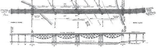
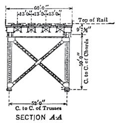
Figure 3. Lindenthal office detail, transverse section drawing. Sway-frames transfer lateral loads from the bottom chord via stiff diagonals to a heavy & rigid lateral system in plane with the top chord truss. Transactions of ASCE, v. 82: 1918.
methods and test results, to understand and standardize the structural properties of bonded steel bars and concrete.
The Superstructure
The lightweight, simple, riveted web trusses are of lightweight Class A open-hearth structural steel. The reverse bow-string (under) deck trusses are constructed of 50-foot high parabolic and parallel arches, set 52 feet apart. The bottom tension chord is comprised of between ten to thirteen pinned eye-bars – the largest size forged to date, each at 38 feet long, 16 inches wide by about two inches thick, and connected by 16 inch-diameter pins tightly covered with cast-iron caps. Twenty-one of the 1,900 tons of annealed structural steel full-size eye-bars were tested before construction, with results of an average elastic limit of 36,500 pounds per square inch (psi) and an ultimate tensile strength of 61,800 psi. The truss structural steel is slightly higher at 66,000 psi, and has a yield point of 35,000 psi (Figures 2, page 34 and 3). There are no transverse supports at the bottom chords. Instead, stiff diagonal sway frames connected to each vertical web member angle up from the bottom chord, transferring wind loads up to a rigid and extraheavy wind and vibration truss in plane with the top chord (Figure 4). The angles and joints connecting the uniform-sized truss members of the reverse bowstring arches are geometrically aligned, so as to equalize and distribute the dead loads. The partially shaded below-deck truss arches experience less equally-distributed exposure to thermal expansion and contraction than would above-deck metal arches. The center of equilibrium, being 15 feet below the support points of the abutments and piers, contributes to the overall stability and rigidity of the structure under dead and live loading. There are fixed bearings in the end spans at the abutments, whereas the center three skewed piers have moveable 24-inch high cast steel rocker bearings as reactions to onesided loading. At the center pier, there is an expansion joint of about six inches. Secondary stresses are relatively large in the end panels. McClintic-Marshall Construction Co. also handled the manufacturing and erection of all the steel for the trusses. Steel gantry travelers erected 11,250 tons of steel. Bents supported the material track at the top chord level, from which the truss members were lifted from below the track by the traveler. After the bottom chords were assembled and laid on adjustable camber blocking, the posts, diagonals and top chords were set in-place by gantry traveler. Total costs of the project were $990,000 (Figure 5).
The Floor
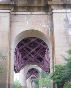
Figure 4. The Buttressed Barrel-Vault Arch at end pier 53, view to the north. The round river-piers and reverse arch spans stand and suspend beyond. Stiff steel sway frame diagonals provide lateral bracing. Concrete cracks, and white alkaliaggregate reaction deposits are active. Many tree roots stress shallow foundations.
For the track floor, a timber floor of treated ties and a reinforced flat slab design were each initially considered, then rejected; for the first, due to the high contemporary cost of timber, and for the latter due to the design team’s cautiousness in depending upon reinforcement to any great extent to resist an assumed axle loading of 70,000 psi plus a 200 percent impact. While the aforementioned standardization studies were ongoing, there remained some distrust, specifically in the reliability and durability of the bonding between the steel and concrete to resist the stresses. Instead, the floor is a solid ballasted type. A skeleton framework of eight-inch I-beams spaced at fifteen inches on center are placed across two stringers laid over one-eighth inch thick steel sheets per track. Five-eighths
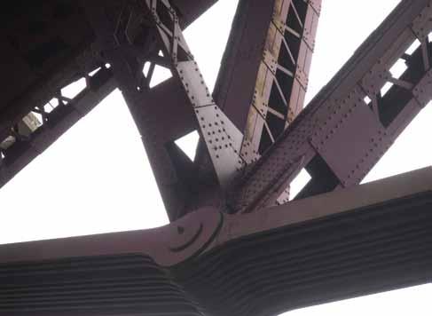
Figure 5. Detail, Little Hell Gate Reverse Bowstring Truss Bridge, 1915. Lower tension chord of eye-bars, with a view up to the deck, illustrating an array of structural steel truss members. Except for the eye-bars’ 16-inch diameter pins, the bridge is riveted to exacting specifications, at the high cost of 25 cents each.
inch tie-rods, spaced ten inches apart, are fixed near the bottom of the I-beams. Three inches below the top, more reinforcing bars are placed longitudinally within the ten-inch thick concrete-encasement, or ballast-surrounded “tray”, poured flush to the bottom surface of the framework. There are embedded four-inch diameter vertically-aligned drain pipes. A two-inch thick timber plank walkway rests on the ends of the I-beams, between each track. The concrete is smooth troweled – one part Portland cement, two parts well-graded sand, and four parts of broken limestone (75 percent three-quarter inch stone and 25 percent screened as per the 1911 AREMA guidelines). Tests in 1915 revealed a compressive strength of 3,500 psi at 28 days. There is a less than 1.8 in 12 transverse slope, with no waterproofing materials.
Engineering Design
The three circular-in-section, skewed doublecolumn river piers positioned between the squared abutment end piers are oriented longitudinally parallel to the inlet water flow, spaced about 296.5 feet apart. As the average spacing of all the other piers in the several miles-long viaduct spans are mostly in the 80+ foot range, the contrasting, large increase in spacing of the Little Hell Gate Bridge spans draws direct visual attention to the unique bridge. In addition, Lindenthal included simple end towers to further highlight the bridge. Gustav Lindenthal considered the Little Hell Gate Bridge significant. The design elements, for example, of repeating various arch schemes throughout the project’s length, punctuated at nodes by outstanding bridges that made advancements in engineering, express aesthetic sensitivity along with structural purpose. Lindenthal intended his bridges to contrast with the many ubiquitous utilitarian truss rail bridges. The end towers, by architect Henry Hornbostel, are hollow, contain interior staircases, and include special crossbeams to carry the contact wires for the early electrification system. The end towers are diminutive as compared to the towers of the nearby Hell Gate Bridge, and therefore do not compete.
Post-Construction Testing and Maintenance
Loadings on the trusses were measured, and all seventy-eight truss connection pins that are under the cast iron caps were tested ultrasonically [ASTM E164] for concealed flaws in 2006. This technology reveals defects, voids

State-of-the-Art Products
STRUCTURAL TECHNOLOGIES provides a wide range of custom designed systems which restore and enhance the load-carrying capacity of reinforced concrete and other structure types, including masonry, timber and steel. Our products can be used stand-alone or in combination to solve complex structural challenges.
V-Wrap™
Carbon Fiber System
DUCON®
Micro-Reinforced Concrete Systems
VSL
External Post-Tensioning Systems
Tstrata™
Enlargement Systems
Engineered Solutions
Our team integrates with engineers and owners to produce high value, low impact solutions for repair and retro t of existing structures. We provide comprehensive technical support services including feasibility, preliminary product design, speci cation support, and construction budgets. Contact us today for assistance with your project needs.
www.structuraltechnologies.com +1-410-859-6539
To learn more about Structural Group companies visit www.structuralgroup.com DUCON® trade names and patents are owned by DUCON GmbH and are distributed exclusively in North America by STRUCTURAL TECHNOLOGIES for strengthening and force protection applications. VSL is the registered trademark of VSL International Ltd.
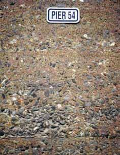
Figure 6. East face, pier 54. Permeable, centuryold weathered concrete surface with exposed, large-sized aggregate which appears to have settled at the time of the pour. Note the one-part Portland cement to one-to-two parts fine-aggregate mortar slushing-edge between the horizontal pour layers. AREMA 1911 Specifications, in use at the time, stated that a uniform distribution of materials shall be obtained with the use of a straight slicing shovel after each pour.
and density of the steel. Readings reflecting off the steel via nondestructive, timed electrical waves in the 0.1 to 25 MHz range were then compared with control data. The tests revealed that the loading and all material capacities were in excess of both historic and current AREMA rating capacities. The century-old cast iron cap-covered structural steel truss joint pins showed no cracking. Concrete surfaces, observed in an October 2014 site trip, exhibited weathering, spalling, cracking, and incipient rust stains, especially at the Little Hell Gate end piers. Much of the original dense concrete protective exterior surface layer (Figure 6 ) is eroded, exposing the interior to destructive alternating wet-dry cycles. Moisture is clearly penetrating the masonry via gravity and wind forces, surface tension, and capillary action. In addition, alkalis in the Portland cement, used in the concrete mix, are reacting with siliceous or carbonate elements in the aggregate. The chemical reaction develops new compounds as gelatinous white alkali within the masonry, which then expands through the masonry to harden on the exterior surfaces. While Portland cement was generally in use by c. 1890, its uniformity and alkali content varied considerably. The reaction phenomenon would be researched after c. 1916, when widespread reports of concrete deterioration emerged. The research continued into the 1950s, at which time the exact science behind the reaction was still little understood (Figures 7 and 8). Cracks and strength-loss result from masonry-mass volume changes. At each end pier there is a continuous vertical crack leading all the way down on both faces of the re-entrant spandrel walls and cornices, and following through the vertex (center) of the six-foot deep barrel-vaulted arch-intrados (soffit), reflecting some displacement of the heavy masonry structural elements. Through-cracks have developed near the springing points in the same manner as at the vertex. Hinges have formed where the lines of thrust converge within the archstructure boundaries. Three hinges produce a statically determinate structure with changing equilibrium and shifting thrust moving increasingly horizontally through the hinging points. Internal and external degradations develop instability and eventual overloading of the structure. The eradication of the Little Hell Gate inlet in 1930s mitigated some of the bridge’s environmental hazards – such as continued exposures to corrosion-causing salty estuarial waters, and scouring at the piers – and contributed in part to the bridge’s low maintenance record. At the time, advancements occurred in paint technology, which indicated that applying a slightly alkaline paint and providing positive electrolytic action via added sulfate of lead, or zinc oxide mixed with linseed oil, was most protective. Lindenthal
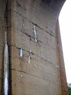
Figure 8. Cylindrical-vault abutment sidewall, end pier 53. Detail of active and desiccated white alkali deposits from reactions between inherent chemicals in the cement and aggregate, thermal effects, polluted air, and moisture. Note the resulting pattern-cracking below the arch springing. Increasing permeability of the mass and incipient oxidation of reinforcement are contributing to the cracking.
knew this, as he used these types of paints on his other metal bridges as far back as 1883. The bridge was painted in 1939 and 1995, with only minor repairs to the steel in 1992. The metal truss is nearly free of rust. The Centennial of this historic and significant project is in 2015.▪
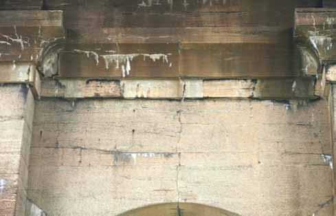
Figure 7. South face end pier 49. Vertical and horizontal popout-cracking, with ongoing severe spalling and alkali-aggregate reaction evident. New compounds from the reaction expand inside the masonry mass; the resulting localized pressure-zones result in microfracturing and spalling of the structure, here seen in the re-entrant spandrel-wall below the cornice. Cracks are oriented parallel to the bars. Volume changes and strength-loss of the masonry-mass are in progress.
Power of the Ring
By Cawsie Jijina, P.E., SECB and J. Benjamin Alper, P.E., S.E.
The Forum in Inglewood, California (also known as the Fabulous Forum) is an arena with a cable-suspended structure – not unlike a suspension bridge. Th ere are 40 columns positioned equally on a 404-foot diameter circle that taper into precast concrete arches which support the 70-foot high compression ring. Forty cables, each 3 inches in diameter, one from each column, are strung from these columns to a central tension ring. Th e entire roof structure sits on the cables. Th e inward force (pull) from the cables is countered by the giant compression ring, which, at the time it was designed, was the largest compression ring in America. In its original design, one hundred percent of the heavy lifting is done by the cables (Figure 1). Designed and built in the early 1960s, the Forum’s structural design favored economy of construction with little concern of future expansion. But music acts today are bringing in heavier and heavier gear – video boards, lighting, LED arrays, speaker banks, rigging – and they want to suspend it all from the roof/ceiling rather than build their own structures. Th e Forum’s roof cables simply did not have enough reserve capacity to support these shows. To further complicate the design, the rigging consultants recommended the addition of a tension grid system to cover almost a third of the cable area under the roof. In a tension grid system, individually framed panels with tensioned wires create a walking surface where riggers can easily walk and drop motorized cables and chains from the primary structure above to support the lights and sounds below. Th is would further increase the demand on the existing roof structure.

One Ring to Push Them
Th e typical demands for increased loading capacity when you retrofi t a building are on the order of 20 or perhaps even 50 percent – but the Forum’s owners wanted to increase the load capacity of the roof by around 300 percent. Th e capacity needed could not be obtained with conventional reinforcement design techniques. A completely out of the box, innovative solution was needed. Inspiration was found in the giant cathedrals of ancient Europe. Th ey are all domed structures, which always have a compression ring at the top in the form of an oculus. Th ey also have a tension ring around the perimeter to resist the dome’s natural tendency to fl atten out. In a dome, all forces radiate outwards. At the Forum, the roles are reversed. Th e compression ring is on the perimeter, and the tension ring is at the center, at a slightly lower elevation. Contrary to a domed structure, in this arena all forces move in a direction opposite to a domed structure. Th is is not a compression structure, but a pure tension structure. Th e ring outside is being pulled inwards because the sag of the cables causes all forces to radiate inward. Th e engineering logic was to create a modern-day version of a dome and marry a new compression structure to the existing tension structure (Figure 2). It would relieve the forces on the existing exterior ). It would relieve the forces on the existing exterior perimeter ring, and generate the extra capacity. A hybrid structure like this had never been designed before – this would be the only structure of its type in the world that had both a tension ring and a compression ring at its center.
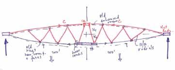
Figure 2. Initial structural concept sketch.
Data Collection
Accurate design requires precise knowledge of the existing structure. As the cables act in a non-linear manner, simple structural analysis methods do not generate accurate results. Possessing the original structural drawings without having the sequencing of the cable erection and jacking, and the original pre-tensioning magnitude, was insuffi cient to accurately model the structure. As the original sequencing and jacking forces of the cable structure were not available, further investigation was necessary. Knowledge of the exact cable location in its current state, and an inventory of the existing loads supported by the cable along with the precise amount of force currently in the cable was required to accurately model the structure in absence of the original sequencing. Measuring the cable locations in space was easily achieved with a 3D laser scan of the ceiling. Th is provided information on the location coordinates of all cables for the entire roof. Finding the existing force in the cable was more complicated, requiring a ‘lift off ’ test of the cable. Th e ends of the existing cables were concrete encased at the completion of installation. During the ‘lift off ’ test, the concrete encasement was chipped away, exposing the end wedge fi tting of the existing cable. A jack with a custom threaded and fabricated pin was used to engage the cable end. Th e cable end
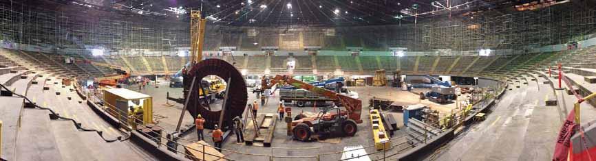
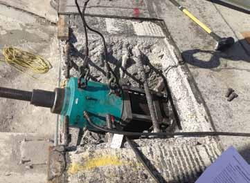
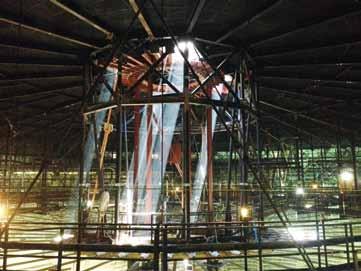
Figure 3. Lift off testing at cable ends. Figure 4. Steel compression ring while being setup for welding on the arena floor.
Figure 5. Steel compression ring being lifted into place at top. Steel tension ring is in view at the bottom.
was then slowly pulled until the end cap of the cable wedge lifted off the compression ring, thereby transferring the entire load from the cable into the calibrated jack (Figure 3). At that one instantaneous moment in time when the cable moves, the point of equilibrium shifts and the existing cable force is determined. This procedure was repeated multiple times. Once all data was collected, it was then input into Severud’s own custom created software, where the output quickly converged, giving the final results.
One Ring to Gather Them
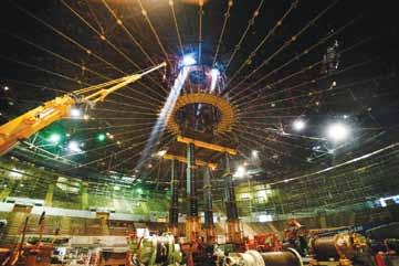
Severud’s design concept envisioned that a new structure would be created within the volume of the existing roof and be seamlessly merged with the existing structure in the same curved roof plane, taking advantage of the subtle curve of the roof (used for drainage). A compression ring was then introduced, like an oculus in a cathedral, except it was fashioned out of steel to bring the entire compression structure together. The new structure, in combination with the existing structure, does all the heaving lifting. The cables continue to support the roof as well as take up any unbalanced rigging loads. Getting the new compression ring into position required careful planning. No mobile crane could just lift this ring up above the perimeter of the roof, reach more than 240 feet from the edge of the promenade at the perimeter of the arena to the center, and then gently lower this massive ring. Severud elected to design the new Compression Ring such that it could be raised up to the roof from the arena floor. That meant that the new compression ring had to slide up through the center opening of the existing Tension Ring to its final top-chord position. That dictated the 19-foot diameter of the ring. Compression forces dictated the 2.5-inch plate thickness (Figure 4 ). False-work was erected, a hydraulic lift was placed, and the new ring was raised into position. The new domed structural framing was then loosely connected to the new Compression Ring and the entire system was allowed to gently settle so that the forces could re-distribute themselves (Figure 5).
One Ring to Tie the Two and Bind Them
Once the new structure settled into equilibrium and all elevations were recorded, the jacks went to work again and raised the new system a precisely calculated amount. The goal was to balance the compression forces from the new structure racing towards the outer perimeter ring with the tension forces from the existing structure racing away from the outer perimeter ring so that the perimeter ring became the binding element. The old tension system was integrated with the new compression system utilizing twenty radial trusses, resulting in a structure dubbed by many of the concert riggers as the ‘best rig on the west coast.’
Rock Concerts, Performance Events, Seismic Events and Asymmetric Loadings
The Forum sits approximately four miles from a seismic fault line. It is in a zone of high seismic activity. It is also a perfectly symmetric structural design. The ideal seismic design is one where the center of mass is coincident with the center of resistance, resulting in a perfect balance of forces during a high seismic event. However, the majority of the concert and performance events are not “In the Round” (centered in the arena) but are “End Stage” events resulting in an asymmetric loading on the structure. The effect is negligible during a routine event but when hanging 300,000+ pounds asymmetrically, it poses a further challenge. The designers had to make
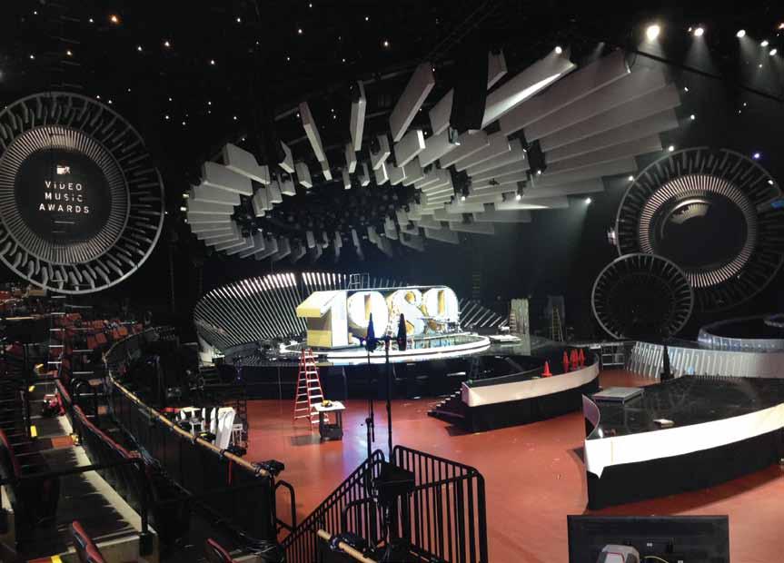
sure throughout the building’s renovation that the building’s center of mass stayed the same, and that the total mass did not increase beyond a set percentage. If an element was added or removed, it had to be balanced out with a similar operation on the other side. It was also necessary to compensate for the addition and removal of loads that were strictly event-dependent. Structural Engineers value redundancy. But performance artistes never conform (that is why they are artists!). The design of the Forum required the study of every possible concert configuration from past concerts and, working with the rigging consultant, potential future concerts. The arena was then re-structured to absorb all of these possible scenarios. Proof of the structure’s performance capability came in August 2014 when the MTV Video Music Awards Event was staged in the arena (Figure 6). A total of 300,000 pounds of equipment, speaker banks, video walls, graphics boards, LED banks, moving catwalks, etc. was hung from this innovative structural system. 300,000 pounds, hanging about 65 feet off center, on a 404-foot clear span caused this tensioncompression structure to deflect a total of 17/8-inch. A very good day in the office. The authors would like to thank Manny Morden, P.E., S.E. for his invaluable efforts on this project.▪ Cawsie Jijina, P.E., SECB, is a Principal at Severud Associates. He can be reached at CJijina@severud.com. J. Benjamin Alper, P.E., S.E., is an Associate at Severud Associates. He can be reached at JAlper@severud.com.
Figure 6. Steel compression ring at the top of the structure to create the dome.
Owner:
Project Team
The Madison Square Garden Company Consultants: Severud Associates: Structural Engineer of Record Brisbin Brook Beynon Architects: Architect of Record ME Engineers: MEP Engineer of Record Clark Construction Company: General Contractor Gafcon: CM/Owner’s Representative Ed Kish Rigging: Rigging Consultant Beck Steel: Steel Fabricator Bragg Steel: Steel Erector IA Stage (Skydeck): Tension Grid Fabricator
ConstruCtible CritiCism
Mitigating SeiSMic HazardS witH realiStic recoMMendationS
By Andy Kizzee, P.E.
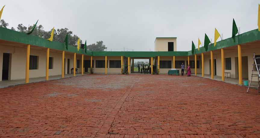
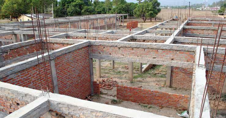
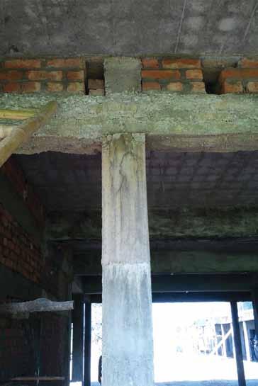
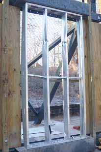
The global structural engineering community is making earthquake-resistant construction a priority worldwide. Much of this effort comes from countries where the research is performed and leading codes are written. Care is being taken to ensure that globally promoted seismic retrofit and reconstruction solutions use materials and techniques that are familiar to local builders. Innovations in earthquake-resistant construction in the developing world must be at a scale that is feasible for the owners and builders not only to understand, but also to implement. A recent Engineering Ministries International (EMI) project in north India provides a good illustration of this principle. The client in question had just completed construction of a new primary school. The rectangular building, opening onto a large courtyard, was designed and constructed prior to EMI involvement. The school was originally intended to have two stories, but the client had not built a structure of this scale before, and neither had the local builder. Construction did not go well, and the local builder was replaced prior to the placement of the first floor slab. The lack of a professional design, coupled with an inexperienced contractor, resulted in subpar construction. As the client came to the realization that the building would likely be unable to support the originally planned second story, he asked the EMI team – on-site to design new buildings for the expanding school campus – to offer an opinion. The EMI team inspected the building and reviewed photos taken during construction. It was quickly confirmed that not only should a second story not be added, but the school was already vulnerable to collapse in the event of a strong earthquake. The first contractor formed and placed the roof-level beams separately from the slab and located them nearly 10 inches too low, then laid three courses of brick to make up the difference prior to forming and placing the roof slab. While unorthodox, this method is stable under gravity loading. However, if earthquake shaking were to cause the three brick courses to crack and be displaced, the reinforced concrete roof slab would
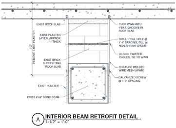
Retrofit detail at interior wall.
only be supported at the corners by the columns. This could cause punching shear failure and potentially collapse. Structural engineers must be aware of their responsibility to inform clients and/or the public of such a hazard, and then make recommendations to mitigate it. If the goal of the recommendations – in this case, seismic retrofit of an existing school building – is to reduce the hazard, then they must be realistic to undertake. An extensive retrofit design that improves life safety does not reduce the hazard at all if it is never actually constructed. In a country with a fully developed building code enforcement system, this recently completed school building would likely not be allowed to be occupied until the structural safety issues were fully remediated. Third-party engineers would be hired, and new reinforced concrete shear walls with large footings would be designed
Roof beams poured independently from the slab.
and installed in many locations throughout the building. The system would be designed according to thoroughly researched and legally enforced building codes. In the event of an earthquake, the stiff shear walls would attract most of the lateral forces, and the building would not be in danger of collapse. If such a fully-designed solution were to be recommended for this remote school in India, however, little good would come of it. Although technically effective, such a solution would likely be deemed too costly and too disruptive to be installed, and the building would remain in its vulnerable state. To reduce the hazard, a seismic retrofit scheme must be relevant to local construction practices and realistic for the owner undertake. It also must be communicated in a culturally sensitive and appropriate way in order to maintain a good relationship with the client and to be able to continue supporting its mission. One way to do this is, whenever possible, to use references from local or regional sources. In India, the Building Materials & Technology Promotion Council (BMTPC), in coordination with many leading earthquake engineering research institutions, has assembled many of the internationally proven details and techniques for earthquakeresistant construction and published them in Hindi, modified for use with regional building types. The school principal, while fluent in both Hindi and English, was excited to receive copies of these materials to distribute to his contractor and other local builders. With these considerations in mind, EMI’s recommendations in this case were as follows: Recommendation #1 – A non-technical solution to mitigate a technical problem
Develop an earthquake drill for students and teachers.
All schools have various safety drills: fire, tornado, security lockdown, etc. Schools in seismic zones should have earthquake drills so that students know how to react. In many countries of the world, students are taught to “Drop Cover & Hold” to protect themselves from falling objects. For this school, the architectural layout of the classrooms is such that it makes more sense for the students to exit
the classroom as quickly as possible and gather in the courtyard away from the building. Recommendation #2 – Technical solutions that can realistically be implemented
Undertake a relatively minor modifi cation to the building.
Removing the plaster from the three courses of brick between the roof beam and roof slab will facilitate the installation of welded wire mesh beneath a fresh layer of plaster. Th e mesh will be anchored to the beam below and slab above, and also tied together on both sides of the wall. Th is will allow the slab to remain supported by the bricks for a longer duration during sustained earthquake shaking. For structural engineers operating in places of the world without fully developed code enforcement systems, it is vital to recommend seismic retrofi ts that will actually be implemented. Th is principle applies not only to technical solutions, but also to any behavioral or human interaction changes that are suggested. For this client, although the risks due to strong ground motions may not be completely eliminated, these realistic recommendations will substantially reduce risk and allow EMI to continue providing technical advice as the school expands in the future.▪
Andy Kizzee, P.E. (akizzee@emi2.org), is a structural engineer and disaster response coordinator for the Engineering Ministries International (EMI) offi ce in New Delhi, India. EMI provides architectural and engineering design services for Christian ministries worldwide (www.emiworld.org).
Th e issue was discovered only by viewing the construction photos as the plaster concealed the slab support condition.
ADVERTISEMENT–For Advertiser Information, visit www.STRUCTUREmag.org


Steel and Cold-Formed Steel Construction

Firms Roll Out New Products and Services
By Larry Kahaner
Companies involved in steel and cold-formed steel construction are bringing new products and services to the market to meet the changing demands of their customers. At SidePlate Systems, Inc. (www.sideplate.com), Jason Hoover, Industry Outreach Executive, says that the new SidePlate fi eld-bolted connection has been gaining traction across the United States. “We use this on wind-governed or low-seismic jobs in regions where fi eld bolting is preferred over welding. SidePlate moment frames are more effi cient than conventional construction, so our designs have always saved tonnage, but recently there’s been a greater push from our clients on speed of construction. Our fi eld-bolted connection saves a huge amount of time in the fi eld, so that’s a big part of its appeal.” Hoover notes that the Strongsville, Ohio, company’s fi rst project done with the SidePlate fi eld-bolted connection was a smaller medical offi ce building in North Carolina. “Th e erector estimated a 21 day schedule, and he fi nished in only 7.5 days. Everyone involved was thrilled with that. “Similarly, we have an offi ce building project in St. Louis where an erector told me that he didn’t like the SidePlate fi eld-bolted connections because the job was going too fast. He said to me: ‘Normally I would have spent all day welding that joint, but with this I’m done in about an hour. We’re going to be off this job weeks early, and now I’ve got to fi nd more work for my guys.’ He did add that he understands why it’s good for the General Contractor and the Owner, though. Th is is the type of ‘negative’ feedback we like to hear.” Hoover adds: “We continue to fi ght misconceptions that SidePlate is simply another 1:1 connection option or that we manufacture something. Th e reality is that our designs improve the entire lateral system, and the connections themselves are built by any steel fabricator. Our staff includes twenty-one structural engineers, but we partner with the entire project team, from the structural engineer of record to fabricators and erectors, to ensure everything goes smoothly.” Amber Freund, Vice President, Operations at RISA Technologies (www.risa.com) in Foothill Ranch, California, would like SEs to know that interoperability continues to be a big priority for design projects. “RISA’s integration with both Revit and Tekla are being used by engineers on both large and small projects,” she says. As for new off erings she notes: “RISA-3D is a comprehensive cold-formed steel analysis and design software which allows you to model using any of the SSMA shapes, as well as custom shapes. In the recent release of RISA-3D version 13, the Cold-Formed Steel code for the AISI 2012, CSA 2012 and CANCERO 2012 was added. Th is update also included the design and code checks for back-to-back Cees and Tracks. Th ese compressive checks were also improved to consider the user controlled unbraced lengths for torque.” In conclusion, Freund says that RISA’s business is growing. “We are continuing to add new products and features to RISA software. We are encouraged to hear more engineers starting new projects, which is a good sign of economic recovery (or at least the start of it).” (See ad on page 76.) Brian Smith, President & CEO of Albina Pipe Bending Co., Inc. (www.albinaco.com) says that his company’s culture fosters a continuous improvement concept when approaching its services. “We are constantly looking to improve the services we provide,” he says of the 3rd generation company based in Tualatin, Oregon. Th is year, 2015, will mark their 76th year in business. “We have found it best to always defi ne expectations with customers. Doing this is not always easy, but certainly something we pride ourselves on. We run an internally designed and programmed computer program. Th is program is all inclusive to every aspect of our business and customer service. Th e most recent advancements implemented to our software are related to scheduling. Our software will factor in variables to help project a completion date as well as a ready to ship date for every job in our shop.” Smith adds: “To also help with customer service we are frequently updating our website. Some recent improvements allow customers to order certain parts online, as well as see customer-specifi c pricing online. Furthermore, we have also posted a virtual tour and videos highlighting many areas and processes in our facility.” Albina provides bent and fabricated items to a number of diff erent end users, Smith says. “We are able to bend a wide range of materials – pipe, tube, plate, square/rectangular and all forms of structural steel – as well as a wide range of sizes from the very small to the very large. In conjunction with our diversifi cation, we adhere to very strict quality and scheduling standards providing customers with what they expect, when they expect it. With our diversifi ed range of materials, and determined eff orts to provide the highest quality products, we have been able to weather the economic downturn seen over the last six years. We have been able to come out stronger than when we were going into the recession.” Also attributable to Albina’s growth and continued success is their focus on capital expenditures. “We are methodically investing in new equipment, tooling and technology to either replace aged equipment or add to our already vast equipment inventory. Capital expenditures have greatly helped Albina stay in front of the curve and remain a leader in the bending industry,” Smith concludes. (See ad on page 48). At Lindapter USA, (www.lindapterusa.com) headquartered in Bradford, England, Marketing Manager Wayne Golden is highlighting one of his company’s latest developments. “Lindapter, the inventor of the original Girder Clamp and Hollo-Bolt, has developed the Type AAF, a new High Slip Resistance (HSR) clamp for connecting
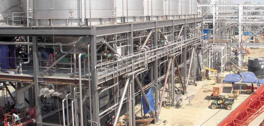
steel sections. This product offers adjustability, anti-corrosion protection and high load capacities, even in low temperature environments,” he says. “Lindapter’s flagship product is the latest addition to its HSR family of clamps designed for high-load requirements including frictional, tensile and combined load applications. The clamp features an innovative two-part design that self-adjusts to suit a range of flange thicknesses, allowing contractors to use a single product type for multiple connection requirements. Typical applications include connecting steel-framed roofs, pipe supports and mechanical handling equipment, while specialist applications include the renovation of bridges and offshore platforms.” Golden says the new product is manufactured from SG iron with specific low temperature properties so the Type AAF provides resistance in cold environments where impact strength is important. “Durability also extends to corrosion protection as the product is supplied with a hot dip galvanized coating as standard. Engineers can be confident that they are specifying a safe and reliable connection, as load capacities have been verified by independent testing.” In conclusion, Golden says: “Compared to conventional methods such as drilling or welding, the Type AAF can be installed in minutes without the need for hot work permits, reducing construction time and labor costs. For additional convenience during installation, Direct Tension Indicators (DTIs) can be used to ensure that the correct tension is applied to the fasteners.” (See ad on page 51). Carlos de Oliveira, CEO at Cast Connex Corporation (www.castconnex.com), is particularly proud that at the 2014 SEAOC Convention in Indian Wells, California, a project utilizing the Cast Connex High Strength Connectors (HSCs) was nominated for an Excellence in Structural Engineering Award. “This particular application was a 43-foot tall support platform at an oil refinery in Richmond, California. The lateral force resisting system of the platform was designed as a Special Concentrically Braced Frame; the brace members were circular hollow structural sections and the bracing connections utilized Cast Connex High Strength Connectors.” The project had unique challenges, “A particular challenge on this project was the time and sequence required to erect the new platform, as the platform was located in the middle of an active refinery. For this client, every day of disruption is very expensive. The High Strength Connectors, which have also been employed in other structures in this facility because they are a very economical seismic brace connection solution, were selected because they enable rapid installation. In the Excellence in Structural Engineering Award application poster, the structural engineer of record from Jacobs stated that the HSCs were selected ‘for ease in erection and smooth flow of forces.’ “High Strength Connectors are designed to be connected to the brace member via a shop-performed complete joint penetration weld around the entire circumference of the section. The completed continued on page 50
ADVERTISEMENT–For Advertiser Information, visit www.STRUCTUREmag.org
Toll-Free: (866) 252-4628 12080 SW Myslony St. Tualatin, OR 97062 info@albinaco.com www.albinaco.com YOUR BENDING EXPERTS
ere is a Price and ere is a Cost!
CHOOSE QUALITY: IT WILL SAVE EVERYONE INVOLVED IN YOUR PROJECT TIME AND MONEY IN THE LONG RUN!
-Angle -Flat Bar -Square Bar -Wide Flange -Channel -Square Tubing -Tee -Rectangular Tubing -Round Tube & Pipe -Round Bar -Rail -Plate USE ALBINA’S CURVED STEEL TO CREATE YOUR NEXT AWARD-WINNING PROJECT!


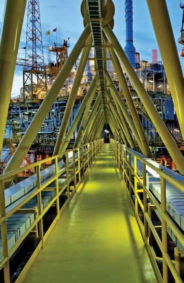
Learn more: www.castconnex.com/products/high-strength-connectors
High Strength Connectors for SCBF. Elegant enough for AESS yet economical enough for industrial uses
braces are then shipped to the construction site, where they are installed via double shear bolted connections to traditional gusset plates. This double shear bolted configuration eliminates field welding of the brace connections and the associated special inspection of those welds, while using a minimal number of pretensioned high strength bolts. From an erection standpoint, the HSC is one of the most efficient bracing connections available, due to erection speed and savings in inspections. Further, given that field welding can be delayed due to weather conditions which would not prohibit bolting, use of the connectors also reduces risk to the construction schedule.” Cold-formed steel stud walls are emerging as a new and attractive option for blast resistant design due to the combination of high strength and ductility that enable them to absorb and dissipate blast energy through large deformation and yielding, according to Nabil Rahman, Director of Engineering and R&D, The Steel Network, Inc., (www.steelnetwork.com) headquartered in Durham, North Carolina. “However, in order to achieve the required energy absorption of steel stud walls requires special attention to the stud-to-track and bridging connection details, which has remained an active area of research and development for The Steel Network, Inc. (TSN) and Applied Science International, LLC (ASI).” Rahman notes: “While much of the existing literature on the topic has described specialized ideal boundaries to ensure that the full tensile membrane response of the studs would be achieved prior to connection failure, the study of commercially-available connections and bridging was lacking. This prompted TSN and ASI to sponsor a series of three open-area blast tests with the University of North Carolina – Charlotte (UNCC) to examine the blast performance of 6-inch cold-formed steel stud wall panels comprised of its BuckleBridge single piece bridging system and VertiClip SL600 head-of-wall connector. “The blast loads applied to the specimens had maximum reflected impulses and peak reflected pressures that were consistently greater than UFC 3-340-02’s design values. Measured ductility limits in the experiment met the limits established by the U.S. Army Corps of Engineers Protective Design Center, which suggests ductility limits between 2 and 5 for cold-formed steel studs. These limits correspond to component damage levels of hazardous failure and blowout respectively, and could be viewed as being somewhat conservative based on the results of these exploratory and limited tests. TSN‘s VertiClip SL600 head-of-wall connection and the BuckleBridge single piece bridging system not only kept the wall intact, but also allowed the studs to develop their end rotation and flexural ductility.” (See ad on page 75.) Design Data (www.sds2.com) of Lincoln, Nebraska, is eager for SEs to learn about its new products. “SDS/2 v. 2015 is Design Data’s newest product that brings major advancements to connection design for steel,” says Strategic Sales Manager Michelle McCarty. “Now engineers can lock in specific variables for connection design and receive immediate feedback through limit states tables and calculations that update on-the-fly. This gives engineers full control over every aspect of the connection and immediate feedback for their design. “SDS/2 v. 2015 also has the recently-added functionality to create CNC files for cold formed steel shapes, allowing users to send DSTV files to the shop to help automate fabrication operations, like copes and holes placed on cold-formed shapes,” says McCarthy.” She says that the company has noticed more engineering companies considering adding steel detailing to their offerings. “Engineering groups are seeing real benefits to including steel detailing as a part of their deliverable, as it reduces RFIs and can decrease timelines, not to mention adding to their bottom lines. Challenges that come along with launching a detailing department include finding the right staff and adjusting your company’s established work process to view detailing as an extension of the engineering process. However, the ability to offer a complete package with fabrication drawings as a part of the deliverable presents more opportunity for profit,” McCarthy says. (See ad on page 53). The 2014 Acquisition of GT STRUDL, (www.intergraph.com) by Intergraph Process, Power & Marine, Huntsville, Alabama, part of Hexagon, has paid immediate dividends with program enhancement releases in 2014 and two more planned for 2015, according to Leroy Emkin, Executive Technical Director. “The highlights are the unique bi-directional capability of frame members and finite elements with GT STRUDL CAD Modeler, incorporation of network licensing through the SmartPlant License Manager (SPLM), Tekla Structures
StruWare, Inc
Structural Engineering Software
The easiest to use software for calculating wind, seismic, snow and other loadings for IBC, ASCE7, and all state codes based on these codes ($195.00). CMU or Tilt-up Concrete Walls with & without openings ($75.00). Floor Vibration for Steel Bms & Joists ($75.00). Concrete beams with/without torsion ($45.00).
ADVERTISEMENT–For Advertiser Information, visit www.STRUCTUREmag.org
Software and ConSulting FLOOR VIBRATIONS
FLOORVIBE v2.20 New Release
• Software to Analyze Floors for Annoying Vibrations • Demo version at www.FloorVibe.com • Calculations follow AISC Design Guide 11 and SJI
Technical Digest 5 2nd Edition Procedures • Analyze for Walking and Rhythmic Activities • Check floors supporting sensitive equipment • Graphic displays of output • Data bases included
CONSULTING SERVICES
• Expert consulting available for new construction and problem floors. Structural Engineers, Inc.
Attention Bentley Users
Have you received your automatic quarterly invoice from Bentley? Would you like to reduce or eliminate these invoices? Use SofTrack to control and manage Calendar Hour usage of your Bentley SELECT Open Trust Licensing. Call us today, 866 372 8991 or visit us
www.softwaremetering.com
interface updated, offshore improvements, and the upcoming GT Menu Graphical Interface update.” He adds that 2014 had provided a rebirth for GT STRUDL through Intergraph’s successful CADWorx & Analysis University Express Global tour (375 attendees), webinars productions (1183 registered attendees), product newsletters, and the creation of the Link-In GT STRUDL Technical User Forum. Says Emkin: “Through this outreach, upcoming development items were identified to complement our Rigorous Response Spectrum Seismic Analysis and the consequences of Nonlinear Geometric Analysis, the need for new/ additional design codes, automatic wind/seismic load generators, and an evolving ‘State of the Art’ integration & interoperability with other Intergraph solutions. “Combing Intergraph’s resources with GT STRUDL’s global network of dealers, trainers, and support staff enables us to deliver an optimized and efficient work process for the following: faster designs with more accurate results produced in hours, not days or weeks; less assumptions leading to safer structure and equipment designs; cost savings realized by evaluating complete systems instead of individual components, and the ability for teams to collaborate and share the same 3D Model to avoid redesign and construction delay cost,” concludes Emkin. (See ad on page 52). Raoul Karp, Vice President of Structural and BrIM Products at Bentley Systems, Incorporated (www.bentley.com) based in Exton, Pennsylvania, says that conditions worldwide have improved with a dramatic increase in construction over the preceding few years. “While some engineering firms have indicated a difficulty in finding qualified hires, others have expressed a hesitation to increase the size of staff because, while there is plenty of work right now, the future is unclear. As a result, engineers at many firms are working longer hours to make up for the manpower shortage. A solution to that problem is to empower engineers to work more productively. To that end, Bentley Systems, Inc. is now offering the new Structural Enterprise License. At little more than the cost of an individual major product license, this license includes STAAD.Pro, STAAD Foundation and all RAM Products including RAM Structural System and RAM Concept. This provides the engineer with the tools that are right for the task at hand. Furthermore, the interoperability capabilities between these programs, as well as with other products outside Bentley from Autodesk, Trimble and others, enable engineers to perform their tasks more quickly and efficiently.” Karp adds: “Several new versions of these products have recently been or will soon be released with powerful new features to meet the demands of domestic and foreign markets, including: STAAD.Pro with AISC 341 Seismic Provisions, global code updates including Canadian and Indian codes, and soon to be introduced major enhancement to the Powerful Input Editor. On RAM Structural System updates include the design of CoreBrace Buckling Restrained Braces and the Canadian concrete and steel code, and RAM Connection with Eurocode 3, provide a big step up in user productivity and enabling fast consideration of design alternatives.” (See ad on page 54). Simpson Strong-Tie (www.strongtie.com) of Pleasanton, California, has three new innovative, cost-reducing utility clips for cold-formed steel construction: the SFC steel framing connector, the SJC steel joist connector and the SSC steel stud connector, according to Randy Daudet, Cold-Formed Steel Industry manager. “New features include pre-punched holes for anchoring to steel or concrete, and intuitive fastener hole patterns to satisfy the structural needs of engineers and simplify installation for contractors. We also recently introduced MSSC kneewall connectors that are designed to work in tandem with
ADVERTISEMENT–For Advertiser Information, visit www.STRUCTUREmag.org
NEW PRODUCT Type AAF Girder Clamp

This unique ‘all-in-one’ adjustable steel clamp offers high slip resistance capability, ease of installation, anti-corrosion protection and performance, even in low temperature environments.
✔ No drilling or welding required ✔ Faster installation and reduced costs ✔ High slip resistance capacities ✔ Independently approved SWL ✔ Low temperature SG iron
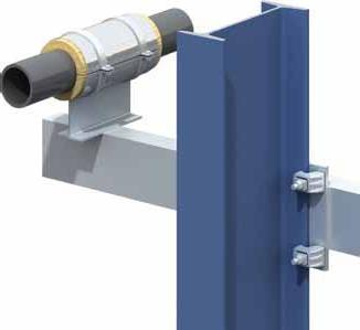


Innovative 2-part design allows the clamp to self-adjust to suit a range of flange thicknesses.

Find us @ 2015
March 25-27 Booth #520


Simpson Strong-Tie BP1/2-3 bearing plates to provide solutions for moment-resisting kneewall applications.” Daudet says that key features of these new utility clips include: • Clips fi t the open side of the stud without having to add track.
Th is adds versatility to the line, and reduces material and labor for contractors. • Clips are easy to specify via our standard round (min) and triangle (max) tabulated loads. Also, versatility is ensured for non-standard designs via square holes that allow engineers to calculate their own screw pattern. “In addition,” says Daudet, “we just launched the LSUBH bridging connector that off ers a lower-cost option to our popular SUBHMSUBH u-channel bridging connectors. Th e LSUBH connector provides all the installation benefi ts of the SUBH/MSUBH connectors, and is suitable for many wind-bearing and load-bearing situations where the load demand is light to moderate. “At Simpson Strong-Tie, we listen to our customers and develop new products that are designed and tested to meet their needs,” adds Daudet. “Engineers and contractors are moving away from fi eld cut clip angles in favor of pre-punched pre-engineered solutions. Contractors save time and money by not having to cut and pre-drill clips. Designers prefer pre-punched pre-engineered solutions because it’s easier for contractors to install clips according to plan and control installation quality.” Simpson Strong-Tie also released a new software program for cold-formed steel Designers that automates product selection and complicated design provisions of AISI, and off ers more robust design tools for users, Daudet notes. “CFS Designer software is the new version of LGBEAMER, a software program that for years has been one of the industry’s most widely used CFS member design tools. With CFS Designer, engineers enjoy the key benefi ts of LGBEAMER, and also have access to connection design and a more powerful software platform. Th e new version maintains the useful design tools that automate common CFS systems such as wall openings, shearwalls, fl oor joists, and rafters, but with an upgraded user interface that makes input faster and more intuitive. Th e software allows the design of multiple engineering models within the same job fi le, and supports connection design for specifi c Simpson Strong-Tie curtain wall and bridging connectors like the SUBH u-channel bridging connector, and the SCB by-pass slide clip.” (See ads on pages 2 and 31).▪

ADVERTISING OPPORTUNITIES
Be a part of upcoming SPECIAL ADVERTORIALS in 2015.
To discuss advertising opportunities, please contact our ad sales representatives:
CHUCK MINOR
Phone: 847-854-1666
JERRY PRESTON
Phone: 480-396-9585
Sales@STRUCTUREmag.org
ADVERTISEMENT–For Advertiser Information, visit www.STRUCTUREmag.org
GT ®STRUDL
Structural Modeling, Design & Analysis

Intergraph GT STRUDL is one of the most widely-used, integrated and adaptable structural analysis solutions in the world. GT STRUDL has a proven track record in a variety of applications such as: nuclear and conventional power generation, on- and offshore facilities, marine, civil,infrastructure, and more. It can fully model, design and analyze structures for the following services:
• Nuclear facilities • Industrial facilities • Offshore platforms/jackets • Roof supports • Power transmission • High-rise buildings • Stadiums • Bridges • Docks, Locks and Dams • Radar dishes and facilities • Construction equipment • Transportation equipment
www.intergraph.com/go/gtstrudl


