25 minute read
Historic Structures
significant structures of the past
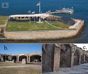
With the invention of mid-19th century naval weaponry, coastal fortifications in the United States were rendered obsolete as they lost their functional use of defense. More than 100 coastal forts, now over a century old, are considered national heritage structures to be preserved for future generations. Many of these brick masonry forts have incurred structural damage during bombardments, and further accumulated damage due to the harsh environments in which they were constructed. There exist no guidelines, however, to assist stewards in the safeguarding of these historically significant masonry fortifications. Therefore, a structural engineer must either rely on modern rules of material Figure 1: The current state of Fort Sumter National Monument: (a) aerial view, (b) barrel vaulted casemates, and (c) degradation of brick and mortar piers. strength and structural behavior, or try to under- the masonry is not continuous at the interface, stand the failure mechanisms of the unreinforced thus forming a cold joint. This design is typical masonry on a more of Third System coastal fortifications in North fundamental level. America, as it served as a method of isolating Modeling of Historic Structures An understanding of unreinforced the impact damage from enemy artillery on the outer walls. masonry can be In this article, we investigate the behavior of achieved through this structure under various foundation settleSimulation-Based a combination of experimental and numerical ment scenarios. Structural Analysis of studies by gaining insights into macro-level strength-deformation behavior and micro-level Finite Element Model Fort Sumter Considering Foundation Settlement defects and crack growth of masonry structures. While uncertainties and errors inevitably arise in the development of such numerical models, experiDevelopment Finite element (FE) analysis is a widely accepted By Sez Atamturktur, Ph.D. and Saurabh Prabhu ments can ultimately reduce such uncertainties and errors in predictions. method for analyzing historic masonry structures due to its ability to model complex geometric 3-dimensional shapes and resolve nonlinear and Fort Sumter National Monument anisotropic material behavior. In the nonlinear analysis of masonry behavior, Dr. Sez Atamturktur serves as an Fort Sumter, in Charleston harbor, SC, is a 19th to represent an appropriate failure criterion for assistant professor in the Glenn century brick masonry coastal fortification. masonry, the elastic modulus, cracking strength Department of Civil Engineering Declared a national monument in 1948, it is and crushing strength of the homogenized at Clemson University. Prior best known as the site where the first shots of the assembly must be defined. This modeling step is to joining Clemson University, American Civil War were fired in 1861. According typically when the majority of uncertainties are she served as LTV technical staff to archival documents, construction began in introduced, due in part to our lack of knowledge member at Los Alamos National 1829 with the foundation, a man-made island (known as epistemic uncertainty) and in part to Laboratory. Dr. Atamturktur may filled with nearly ten thousand tons of granite the natural variability of the material (known as be reached at sez@clemson.edu and over sixty thousand tons of assorted rocks aleatory uncertainty). Any laboratory tests or on and further information about and aggregate. By 1860, the pentagonal-shaped site evaluations of material characteristics would her work can be found at structure (Figure 1a) rose nearly 50 feet high, help reduce the epistemic uncertainties, while the www.cuideas.org. with three tiers built with locally made bricks aleatoric uncertainty (such as the spatial variabilSaurabh Prabhu is a graduate student in the Glenn Department of Civil Engineering at Clemson University. Mr. Prabhu may be reached at saurabp@clemson.edu. and Rosendale mortar. After several devastating bombardments between 1861 and 1865 and reconstruction efforts lasting into the early 20th century, only the lower first tier of the original fort stands with major portions reconstructed. The walls are made up of barrel vaulted casemates ity of masonry) inevitably remains in the model predictions. During our studies on Fort Sumter, a prism sample along with 2.5-inch diameter cored samples were obtained on site (Figure 2, page 28). The compressive strength and modulus of (Figures 1b and 1c) that once held guns and artil- elasticity were determined according to ASTM lery. Each casemate has a gun embrasure opening standard tests parallel and perpendicular to the in the exterior scarp wall allowing artillery to fire mortar bed joints. The tensile strengths of the from the fort in all directions. The scarp wall, brick and mortar samples are determined via is adjacent to the casemate piers and vault, but three-point flexural tests. The tensile capacity
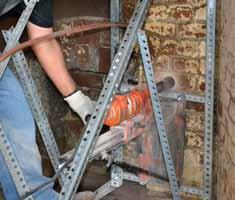
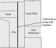
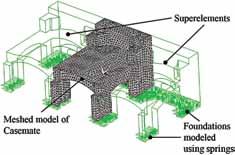
Figure 2: Coring of material samples revealed that although the construction drawings indicate a brick wall across the width, the construction of the fort is composite with tabby concrete infill. Figure 3: The discontinuity between the scarp wall and barrel vaulted casemate isolates the structural damage to the scarp wall to prevent the casemate from collapsing in the event of an attack. Figure 4: The finite element model of the casemate is built recognizing the elastic constraints of the adjacent casemates as well as the unmodeled foundation.
of the brick-mortar assembly is taken as the volumetric average of a representative cell. The properties of the tabby concrete infill are determined via diametral tests on the cored samples. Lastly, the densities of the materials are measured by taking a ratio of weight to volume of the specimen. Historic masonry monuments are typically a complex network of curved elements such as arches, vaults, domes, and buttresses with straight elements such as piers and walls. Some structural elements may also contain decorative moldings, surface texture or damage such as minor chipping, etc., making it difficult to reproduce the geometry in a numerical model. Such details can unnecessarily increase the model complexity and, thus, the computational demand. The fundamental principle in geometric modeling must be preserving the structurally important geometric features, such as cross sectional area, center of gravity, moment of inertia, etc. Over the past 150 years, Fort Sumter’s infrastructure has undergone significant and permanent deformations, material degradation, and discontinuities due to crack formations. In our study, terrestrial 3-D laser scanning with a Trimble CX scanner was implemented to digitally reproduce the fort’s geometry. A 3-D non-linear FE solid model of one of the casemates was developed using ANSYS 13.0. The model geometry was constructed from the wireframe models developed using the laser scan, and initial material properties were assigned according to the material tests. In analyzing masonry with the finite element approach, the geometric model was meshed with specialized elements designed for brittle materials accounting for cracking and crushing according to a predefined failure criterion. The size of the mesh was determined based on the trade-off between numerical accuracy and run times. A mesh size of 0.2 meters typically yields a numerical uncertainty below the variability in the structure’s expected response due to environmental factors (5-6%). In our study, the discontinuous interface between the scarp wall and vaulted portion of the casemate (Figure 3) was treated as a contact surface and approximated by a friction coefficient. The coefficient was calibrated according to an experimentally measured ratio of displacements on the two sides of the interface when an instrumented hammer was used to impact one side. The casemate foundation was modeled assuming a linear relationship between the pressure on the foundation and the deflection, i.e. a Winkler type foundation. Thus, a series of vertical and horizontal linear springs was distributed throughout the base of the casemate. The stiffness of the springs represented the foundation stiffness, which required calibration to the experimental data. When developing finite element models of large masonry monuments, it is often necessary to isolate a portion of the structure. Such an approach, although necessary to keep the problem to a manageable size, results in unknown restraining forces between the structure of interest and components that are excluded from the model. To account for these unknown forces, the most computationally efficient approach is substructuring, which entails approximating the force-displacement relationship of the adjacent components through a small number of elements located at the interface. These elements are known as superelements, and they significantly reduce computational demands. While modeling one of the casemates of Fort Sumter, the adjacent casemates are represented with superelements, effectively reducing the problem to one third (Figure 4 ).
Calibration of Material Properties
Calibration refers to the systematic adjustment of model input parameters to match the solution with experimental observations. Non-destructive vibration tests were performed to extract the natural frequencies of the casemate, such that the model input parameters can be fine-tuned by comparing the predicted natural frequencies with actual measurements. Accelerometers were used to measure 30 minutes of ambient vibrations on 41 points on the casemate. The vibration response of the casemate, recorded in the time-domain, was post-processed to extract the first two natural frequencies at 27.48 Hertz and 45.2 Hertz. Natural frequencies are linear properties of the global behavior of the system and, thus, were used to calibrate material parameters that define linear behavior and boundary conditions. For the FE model of the casemate, three input parameters were selected for calibration: the elastic modulus of both the barrel vault and the walls and piers, and the stiffness of the foundation springs. The calibrated input parameters were obtained such that the FE model reproduced the measured natural frequencies with 10% accuracy.
Support Settlement Analysis
Four settlement scenarios were considered with smoothly varying profiles including sagging settlements, pier settlements and tilting of the ground. Each settlement scenario is simulated with a maximum magnitude of 100 mm in increments of 2.5 mm. Scenario 1 (Figure 5) simulated an unsymmetrical sagging in the north-south direction, including both the scarp wall and piers. With this scenario, a significant through crack originating at the base of the scarp wall on the south side ran diagonally across the scarp wall. Also, severe cracking at the springing
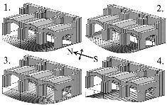
Figure 5: The four settlement scenarios considered in the analysis.
of the arch on the south-side was observed. Scenario 2 simulated symmetrical sagging under the casemate in the north-south direction. This scenario resulted in a crack that began at the base of the scarp wall at both ends and converged in the center, forming a load bearing arch. Scenario 3 simulated the settlement of the north piers. Differential settlement of a pier caused an unsymmetrical cracking of the vault close to the pier that has settled, while the pier that has settled less experienced more damage. Scenario 4 constituted the tilting of the casemate in the north-south direction. This scenario resulted in heavy cracking of the south pier, diagonal cracks in the scarp wall and a rapidly developing through crack in the vault. Cracking in the vault must be treated as an instability condition as the progression of cracks once initiated in these members was rather rapid (Figure 6).
Summary
The computer simulation indicated that unsymmetrical sagging types of settlements were characterized by diagonal cracking of the scarp wall, originating from the bottom on the less-settled side. Symmetric sagging under the casemate, however, formed cracks that originate from the bottom of the scarp wall from both sides and converge at the center forming an arch that spans the length of the casemate and bears the loads of the wall above. Cracks due to stress concentrations were seen for most settlement configurations at the intersection of structural members, such as the springing of the arches and vaults. Cracking of the vault was observed in configurations that involve differential settlements of the piers. Cracks, once formed in the vaults, progressed rapidly without warning as settlement increased. Thus, cracking of the actual vault should be taken as a structural stability concern. The formation and progression of cracks were observed to be unique to each settlement configuration.
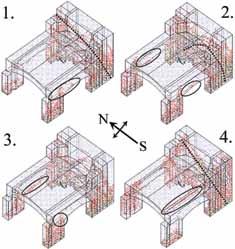
Figure 6: Crack development under the settlement scenarios shown in Figure 5.
By utilizing visual investigations of these peculiar early warning signs in the form of cracks, the stewards of this historic monument can use these computer simulations to help draw conclusions whether settlement may be causing damage to the structure. This of course assumes that the cracks are not due to external loads, which too can be incorporated into the numerical model, making simulations a useful tool for historic structural assessment.▪
ADVERTISEMENT–For Advertiser Information, visit www.STRUCTUREmag.org


Rebuilding the Walls of Fort Jefferson
By Craig M. Bennett, Jr., P.E.
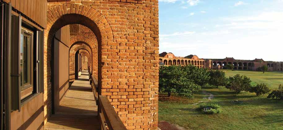
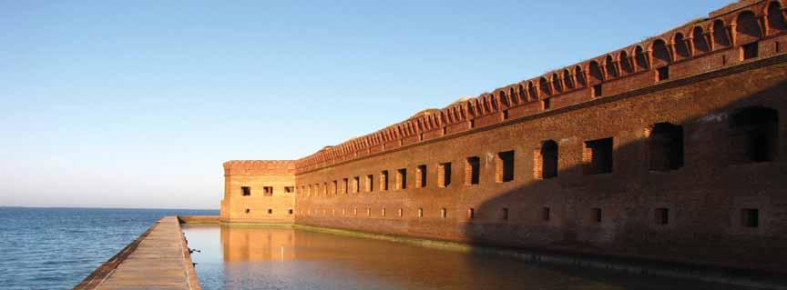
Fort Jeff erson National Monument is located in the Dry Tortugas, a group of sand bars 70 miles west of Key West, Florida. Th is great pile of 16 million bricks surrounding coral concrete cores was originally intended to defend a harbor for ships of the US Navy, allowing the naval forces to control shipping through the Straits of Florida and, ultimately, to control trade through the Gulf of Mexico and into the Mississippi River. Th e fort occupies over seventy percent of Garden Key, one of the larger islands of what is now Dry Tortugas National Park (Figures 1, 2 and 3). Th e history of the construction of the fort is bewildering. Noted in 1829 by U.S. Navy Commodore John Rodgers as an ideal location for an advance post for the defense of the Gulf Coast, the study and design process occupied the next 17 years, culminating in 1846 with the start of construction. Th e fort was still not complete in 1865 at the end of the Civil War, by which time the invention of rifl ed cannon had made the fort itself obsolete. Th e fort was used, unfi nished, as a Federal prison during and after the Civil War. It still remains unfi nished today, serving as a marine research station and a National Park. Now accessible primarily by seaplane and ferry, the fort that once housed Dr. Samuel Mudd, imprisoned for tending to John Wilkes Booth’s broken leg, sees up to a few hundred visitors a day who take either a 45 minute seaplane ride or an almost three hour ferry ride
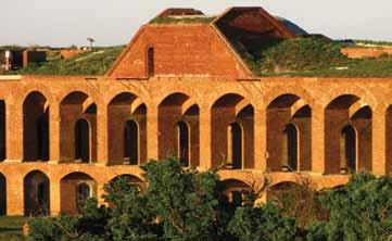

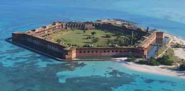
Figure 1: Fort Jeff erson, in the Dry Tortugas, is in a serenely beautiful setting, accessible primarily by ferry and seaplane.
from Key West to tour the casemates, snorkel among the sergeant majors and parrot fi sh, and occasionally camp at the edge of the beach. Th e fort has more than its share of structural issues, all of them issues that structural engineers face in working on many of our older masonry structures. Settlement, loss of mortar and, most importantly, damage by embedded metals have nearly destroyed portions of what the rifl ed cannon never had the opportunity to try to take out. Many of us see settlements in the neighborhood of an inch or two, and occasionally several inches, on existing structures. But between the middle of Front 2 and the tip of Bastion 1 at the fort, a distance of approximately 200 feet, the fl oor of the second level of the fort drops almost 24 inches, giving an average grade of one percent over that distance (Figure 4). Th e casemates show the movement with fracturing of the vaulting that makes modern structural analysis particularly challenging. Structural engineers are likewise accustomed, on many domestic buildings, to seeing masonry walls in need of repointing. But fi nding walls where bricks can be removed by hand is, fortunately, less
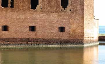

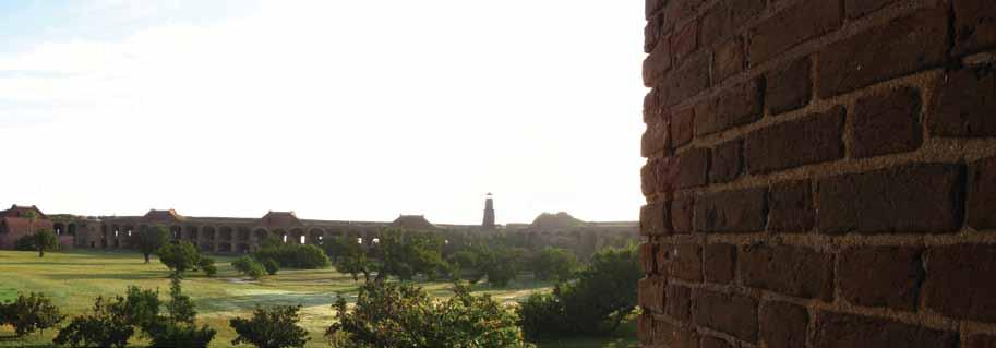


Figure 5: Mortar loss is severe in many areas.
Figure 6: Corrosion of the embedded iron Totten shutters has severely damaged the masonry surrounding the embrasure openings. Figure 2: Th e fort is reported to be the largest masonry structure in the western hemisphere.
common. Not here at Fort Jeff erson, where 160 years of moisture migration through masonry has left mortar so deeply eroded that bricks falling and touching bricks below is far from uncommon (Figure 5). Fort Jeff erson’s greatest challenge comes from embedded iron (Figure 6). Th e great military engineer, Joseph Totten, designed iron shutters to close and protect the embrasure openings from cannon fi re. Unfortunately, the eight-inch thick, 1500-pound armor blocks were embedded between 18 and 24 inches into the masonry walls of Fort Jeff erson. On Fronts 4 and 6, as well as on other portions of the fort, the damage to the scarp walls has been so severe that the iron has had to be removed and the walls rebuilt to a depth of as much as 24 inches (Figure 7). Reconstruction of these vaulted, loadbearing masonry walls was particularly challenging, as was any work at all 70 miles from the nearest building supply store. Th e logistical challenges of working in a particularly isolated environment were handled by a construction crew under the direction of Ken Uracius of Stone and Lime Imports and owner’s representative Kelly Clark of the National Park Service. Th e engineering design team, with input from the architecture team led by Susan Turner of Lord Aeck Sargent, was able to focus on the challenges of large-scale brick growth, tying new vaulting into existing, horizontal reconstruction of a structure originally built vertically, and movement and potential collapse of unresisted thrust in the vaulting. In modern construction, it is common to leave regularly spaced expansion joints in brick masonry, roughly every 24 feet in the southeastern Unites States. But the reconstruction of Fronts 4 and 6 required that roughly 400 feet of brick walls (Figure 8, page 32 ) be rebuilt without jointing and be done on a relatively tight schedule, with a non-hurricane working window of only six months a year. Fortunately, experience with similar issues at Fort Washington, Maryland had taught the team that they were able to force early permanent growth into the masonry with extended submersion of the bricks. Careful measurement work on extended brick soaks by Mike Schuller’s team at Atkinson-Noland of Boulder, Colorado had shown that seven to 28 day soaks could force enough growth in the bricks prior to
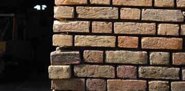
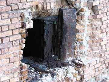

Figure 8: Front 4, now rebuilt, has over 400 feet of scarp without expansion joints.
their installation to avoid pushing the bastions apart. Without the pre-wetting, up to four inches of wall movement was anticipated. Tying new vaulting on the face of the scarp walls back into the existing vaulting behind the scarp was interesting. The Florida State Historic Preservation Officer had asked the team not to use metals to make a tension tie of the new construction back to the existing, although Series 316 stainless steel and bronze both have reasonably good track records of holding up well in a marine environment. By
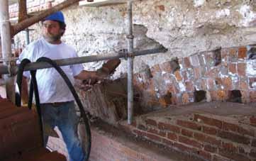
Figure 9: Tie bricks let into the undamaged vaulting tie the new vaulting into the old. The coral concrete is seen above. judiciously cutting in the existing vaults and laying in tie bricks (Figure 9) then carefully laying out the brick coursing around the ties (Figure 10), the team was able to achieve a continuity similar to the original. The original 19th century construction of the fort had, of course, proceeded vertically from the ground upward, building centering (formwork) for the vaulting and removing the centering once the vaults had been built. Reconstruction was instead horizontal (Figure 11), starting in the moat and moving horizontally into the scarp walls, shoring as necessary and depending on arching action overhead wherever possible. Reconstruction did require that the brick coursing
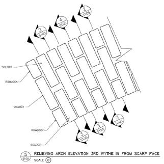
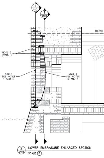
Figure 11: Even though the original construction was built vertically from the ground up, the reconstruction had to be horizontal working from the interior outward to the scarp.
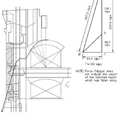
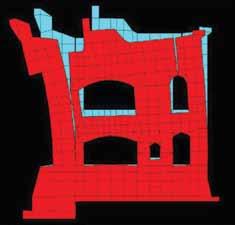
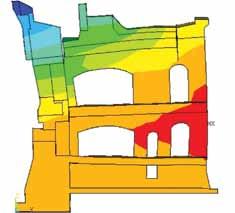
Figures 12, 13 and 14: Graphic statics calculations and two finite element models and confirmed that, without the scarp, the arch supporting the vaulting was on the edge of stability.
be laid out, course by course and wythe by wythe, in order to match the tie bricks and achieve the final bond pattern. Finally, the greatest concern was the possibility that deep cuts in the scarp wall could destabilize the casemate vaulting behind the scarp. Three different analytical models (two finite element and one based on graphic statics) had shown that the arch supporting the vaulting was close enough to being unstable (Figures 12, 13 and 14) that the depth of the reconstruction had to be tightly limited and that certain columns had to be restrained during the disassembly and reconstruction. While only one of the four engineering challenges of the construction was readily apparent before the design started, a careful focus on the short and long-term behavior of the materials and of the historic structural systems, combined with input from the whole owner, design and construction teams led to a successful reconstruction of two of Fort Jefferson’s failing scarp walls.▪ This article is a condensation of presentations given at The Association for Preservation Technology, Victoria, British Columbia in September, 2011 and at The Masonry Society, San Antonio, Texas in October, 2011. Those presentations focused on different aspects of the same project.
Craig Bennett, P.E., of Bennett Preservation Engineering PC, is a structural engineer focusing exclusively on existing, and primarily historic, structures. He can be reached at CBennett@BennettPE.com.
ADVERTISEMENT–For Advertiser Information, visit www.STRUCTUREmag.org

New Theory on Egypt’s Collapsing Pyramids
By Peter James
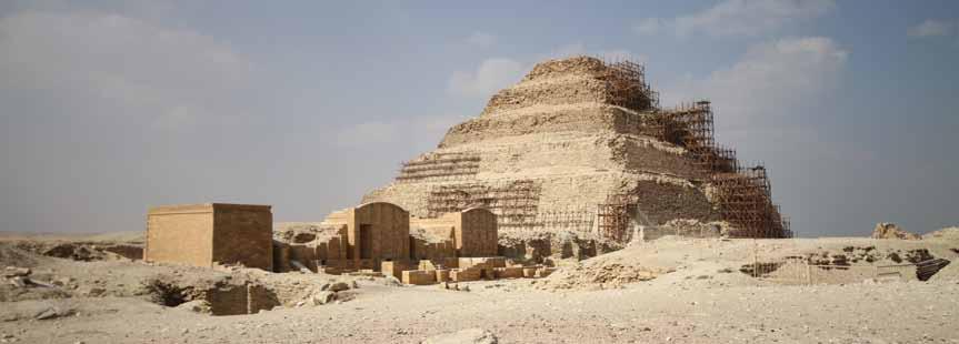
The author’s first introduction to working in Egypt was a project in Cairo’s historic old quarter following the 1992 earthquake that caused widespread and devastating damage. Cintec International began working on a contract to repair and reinforce a number of badly affected structures, including some 15 notable mosques and maqaads, which were strengthened using the firm’s patented anchoring systems. Following success in the old quarter, the focus moved to the internal reinforcement of the Temple of Hibis in the El-Kharga Oasis, 700 kilometres (434 miles) due south of Cairo. Construction on the Temple began in 672 BC, but unlike most other comparable structures, it had differential settlement problems due to poor soil conditions. Work on these buildings was completed with no damage to the splendor and history of the monuments. Soon afterwards, Cintec undertook its first pyramid restoration projects. These involved strengthening the connecting burial chamber corridors and ceilings of Egypt’s Red and Step Pyramids. The Red Pyramid is the third-largest of Egypt’s pyramids and was the first “true” pyramid built by Pharaoh Sneferu. Sneferu had built two previous pyramids, but these were not of a true triangular shape, and for structural reasons were not chosen by the Pharaoh as his final resting place. While work on the Red Pyramid was confined to strengthening the granite slabs immediately above the burial chamber’s corridor, Cintec’s next project, the Step Pyramid (Figure 1), required more careful planning and execution due to the very dangerous condition of the burial chamber ceiling. A large portion had collapsed during the 1992 earthquake, and what remained – a ragged, hanging, inverted group of large and small stones set in mud – was liable to collapse at any time. Cintec used its unique WaterWall airbags to support the ceiling temporarily without provoking further stone fall, before beginning work on final anchoring processes which are now halfway to completion. These ongoing projects offered insight into the nature of the pyramids’ structural deterioration.
The Bent Pyramid
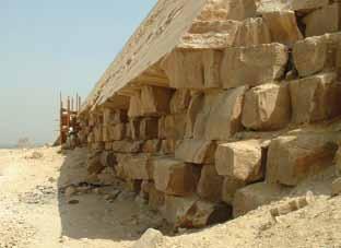
On one of the author’s visits to the Step Pyramid, he was asked for an opinion on securing the remaining outer cladding of the Bent Pyramid (Figure 2), another construction by Pharaoh Sneferu, located 40 kilometers south of Cairo. This pyramid’s top section sits at a slightly different angle to the main body, giving the structure its “bent” appearance. Before any structural restoration work could be considered, the exact nature of the pyramid’s defects had to be established so that the correct intervention could be carried out. From a visual inspection, the structure showed distress along all of its extremities (Figures 3 and 4). What were the clues? The pyramid did not appear to have
Figure 1: The Step Pyramid.
any foundation movement. All of the missing cladding occurred at interfaces or changes of direction at the angles and between the ground and the cladding. A popular theory is that the missing cladding was removed by local opportunist thieves. At the lowest levels that could be the answer, but the same condition occurs at higher levels and in an apparently random manner, with no signs of indentations from temporary scaffolding or of any symmetrical cutting of the blocks to aid removal. It would have been extremely dangerous work. To dismantle a structure, you normally need as much scaffolding as you would to build it, and opportunist thieves would hardly have had sufficient resources. Indeed, if they merely wanted rough stones, they could have found them in the hills adjacent to the center of Cairo without the trouble of removing and transporting them 30 miles out of town. The damage here appears to be caused by a giant whose hand has swept across the face of the pyramid with enormous energy, sucking out the facing and leaving the ragged empty sockets. It is the author’s belief that in the case of the Bent Pyramid – in fact, in the case of all pyramids – the outer casing has been affected by thermal movement. The Bent Pyramid is the only one with any degree of stone casing still attached, making the mechanism of failure apparent. The distress at all of the perimeter edges suggests that the outer casing has expanded from the center outwards, and movement has taken place on all of the extremities.
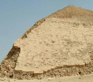
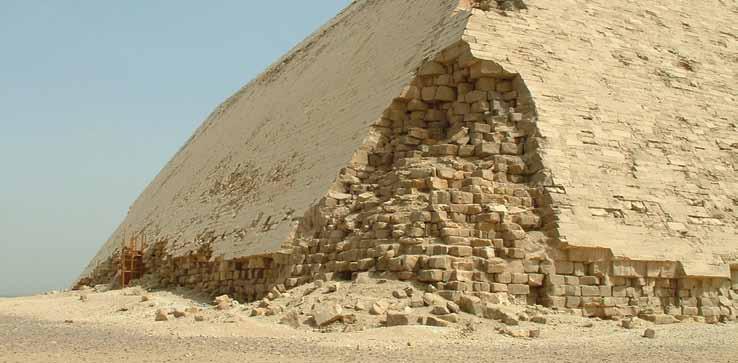
Figure 4: Limestone blocks cantilever out, where cladding below is no longer present, and eventually fail. Figure 3: Major cladding damage at one corner of the Bent Pyramid.
It has been suggested that the original dimensions recorded by Flinders Petrie were inaccurate and that the dimensions taken in 2004 were larger by a small degree. This is to be expected of a structure that is still moving and increasing in size. Furthermore, the convex shape of the pyramid’s outer casing could be caused by the stones arching between fixed points. The transit of the sun across the region will vary over the seasons, heating one side more than another, giving rise to disproportionate movement, particularly at the extremities.
Temperature Variation
During the day, the temperature rises to 40⁰C (104⁰F) across the face of the outer casing, then at night cools to 3⁰C (37⁰F) because of the lack of cover and exposure to the prevailing winds. This gives an average daily temperature fluctuation of 37⁰C (67⁰F). The photographs of the Bent Pyramid show how thermal expansion has caused the blocks to move to the edges, where they have detached. It also shows how individual stones, unsupported, can cantilever and snap off and subsequently fall to the ground. Limestone has a coefficient of thermal expansion of 8x10-⁶, proportional to the change of temperature and to the original dimensions. Applying this yields (8x10-⁶) x (37⁰C) x (100m) = 30mm (1¼ inches) of movement per 100-meter (328-foot) run in all directions, although this is also dependent on the size of the gaps between adjacent stones. All movement from the thermal expansion of the casing would be taken up initially in the joints, but would also cause dust and stone particles to detach from the stones, filling the voids and gaps between them. This would reduce the amount of contraction possible at night, along with the stones’ natural propensity not to return to their original dimensions and position, and so the cycle would start again. Multiply this endless movement by the number of days that the pyramid has been erected and you have the reason why all the outer casing has moved to the extremities, where it has buckled or displaced against blocks moving in the opposite direction and then fallen off. It may then have been picked up by opportunists and removed from the site.
Additional Questions
Another important question to consider is this: Why does the Bent Pyramid still have half of its outer casing attached, while the Red Pyramid and the Great Pyramids at Giza have virtually none? I believe that this is due to the increased skills of the craftsmen, who developed more knowledge and precision as the process of pyramid construction developed. They became able to provide better accuracy, build quality, and jointing of the slabs. The Bent Pyramid was probably built with less care, and with more voids between the stones that acted like expansion joints. The casing blocks being inclined inwards at the base of the pyramid may have limited the expansion. Finally, could the sight of the progressive damage to the outer edges of the pyramids, that would have taken place relatively soon after their construction, be the reason that – having spent so much time and energy constructing these wonderful monuments – the Egyptians changed their burial method to the Valley of the Kings? While the author is keen to stress that this is his opinion, rather than evidential fact, he suggests that thermal movement led to the crumbling of these magnificent structures, and eventually to their discontinued use.▪ Peter James (peterjames@cintec.co.uk), is the Managing Director at Cintec International in Newport, South Wales, United Kingdom. He has worked on projects around the globe, strengthening and restoring historically significant structures from Windsor Castle to the parliament buildings in Canada.


