35 minute read
CODE UPDATES


The American Concrete Institute (ACI) published the Building Code Requirements for Structural Concrete (ACI 318-14) and Commentary (ACI 318R-14) in the Fall of 2014. ACI 318-14 has been adopted by reference into the 2015 International Building Code (IBC). There are very significant organizational as well as technical changes between ACI 318-11 and ACI 318-14. This is the second of a two-part article on these changes: Part 1 (STRUCTURE, April 2016) described the organizational changes, and this Part is devoted to the technical changes.
Overview of Technical Changes
In view of the effort involved in the complete reorganization of ACI 318-14, the initial expectation was that the number of technical changes in ACI 318-14 would be minimal. However, it did not end up that way. ACI 318-14 contains a number of significant technical changes, with some of the most significant ones discussed below. Chapter 1 – General The new Section 1.5 – Interpretation is an important addition to Chapter 1. This section tells the user how to properly interpret ACI 318 provisions. Chapter 2 – Notation and Terminology A new sentence has been added to the definition for “hoop.” It reads: “A closed tie shall not be made up of interlocking headed deformed bars.” The term “special seismic systems” has been newly defined as: “structural systems that use special moment frames, special structural walls, or both.” Chapter 4 – Structural System Requirements This new chapter contains sections on: Materials, Design Loads, Structural System and Load paths, Structural Analysis, Strength, Serviceability, Durability, Sustainability, Structural Integrity, Fire Resistance, Requirements for Specific Types of Construction, Construction and Inspection, and Strength Evaluation of Existing Structures. Most of these sections refer to other chapters in ACI 318-14. The section on Construction and Inspection, for instance, refers to Chapter 26. ACI 318-14 does not have specific requirements concerning sustainability and fire resistance. The section on Sustainability permits the licensed design professional to specify sustainability requirements in the construction documents. The strength, serviceability, and durability requirements of ACI 318-14 are required to take precedence over sustainability considerations. In the section on Fire Resistance, ACI 318 refers to the fire protection requirements of the general building code, which is the legal code used by the authority having jurisdiction over the structure. Chapter 5 – Loads For many code cycles, ACI 318 retained provisions Code
for service-level earthquake forces in design load Ucombinations. Any reference to service-level earthquake forces has been deleted from ACI 318-14. pdates A requirement to include secondary moments was rightly included in the ACI 318-11 section on Moment Redistribution but was not included anywhere else. Since secondary moments are a code developments and announcements significant consideration in member design even when moments are not redistributed, they should be included in the member chapters. Also, the effects of reactions induced by prestressing include more than just secondary moments. Thus, Section 5.3.11 now states: “Required strength U shall include internal load effects due to reactions induced by prestressing with a load factor of 1.0.” In the chapter on one-way slabs, Section 7.4.1.3 now requires: “For prestressed slabs, effects of reactions induced by prestressing shall be considered in accordance with 5.3.11.” Sections 8.4.1.3 and 9.4.1.3 have similarly been added to the chapters on twoway slabs and beams, Significant Changes between ACI 318-11 and ACI 318-14 respectively. Chapter 6 – Structural Analysis Part 2: Technical Changes ACI 318-11 and prior editions were silent on the use of finite element analysis (FEA). Chapter 6 By S. K. Ghosh, Ph.D. has added a new Section 6.9 with provisions that are intended to explicitly allow the use of FEA and to provide a framework for future expansion of FEA provisions. The added provisions are not meant to serve as a guide for selection and use of FEA software. The new chapter on Diaphragms and Collectors makes an explicit reference to the use of FEA. This made it imperative for ACI 318 to recognize the acceptability of its use. S. K. Ghosh is President, S. K. Chapter 8 – Two-Way Slabs Ghosh Associates Inc., Palatine, IL and Aliso Viejo, CA. He is a ACI 318-11 Section 18.9.1 required a minimum long-standing member of ACI area of bonded reinforcement to be provided in Committee 318, Structural all flexural members with unbonded tendons. Concrete Building Code, and ACI 318-14 Section 8.6.2.3 requires the same its Subcommittee H, Seismic minimum bonded reinforcement in slabs with Provisions. He can be reached unbonded or bonded tendons, except that the at skghoshinc@gmail.com. area of bonded tendons is considered effective in controlling cracking. The structural integrity requirements in ACI 318-11 Section 18.12.6 applied to two-way posttensioned slab systems with unbonded tendons only. The structural integrity requirements in ACI 318-14 Section 8.7.5.6 apply to two-way post-tensioned slab systems with unbonded as well as bonded tendons. Chapter 9 – Beams The online version of this article has detailed An extensive PCI-sponsored experimental and references. Please visit analytical research program was conducted at www.STRUCTUREmag.org.
Figure 1. Knee joint with headed beam reinforcement.
North Carolina State University. The results of this research demonstrated that properly designed open web reinforcement is a safe, effective, and efficient alternative to traditional closed stirrups for slender precast spandrels. A simple, rational design procedure was developed. This proposed procedure significantly reduces reinforcement congestion, especially in the end regions of slender spandrels, while maintaining a desired level of safety. This led directly to the inclusion in ACI 318-14 of new Section 9.5.4.7, which reads: “For solid precast sections with an aspect ratio h/bt ≥ 4.5 [bt = width of that part of cross section containing the closed stirrups resisting torsion, in.], it shall be permitted to use an alternative design procedure and open web reinforcement, provided the adequacy of the procedure and reinforcement have been shown by analysis and substantial agreement with results of comprehensive tests. The minimum reinforcement requirements of 9.6.4 and detailing requirements of 9.7.5 and 9.7.6.3 need not be satisfied.” Chapter 12 – Diaphragms ACI 318 has, for many editions, contained design and detailing requirements, found in ACI 318-14 Section 18.12, for diaphragms in structures assigned to Seismic Design Category (SDC) D, E, or F, defined in ACE 7-10. ACI 318-14 has, for the first time, added design provisions in the new Chapter 12 for diaphragms in buildings assigned to SDC C and lower. The new chapter applies to the design of nonprestressed and prestressed diaphragms. The diaphragms may be castin-place as well as precast with or without topping. The topping may be composite or non-composite with the precast units. Chapter 18 – Earthquake Resistant Structures Some of the most important technical changes are found in Chapter 18, Earthquake Resistant Structures, and include the following:
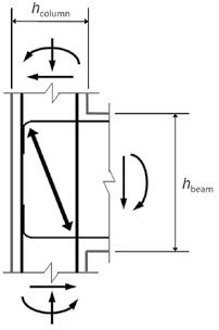
Figure 2. Compression strut in joint with high aspect ratio.
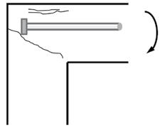
1) Confinement requirements for columns of special moment frames with high axial load or high concrete compressive strength are significantly different for the regions of potential plastic hinging at the two ends. The changes are in recognition of the dependence of the amount of required confinement on the magnitude of the axial load imposed on a column and on the strength of concrete in the column. The new requirements also recognize the fact that longitudinal reinforcement that is well distributed and laterally supported around the perimeter of a column core provides more effective confinement than a cage with larger, widely-spaced longitudinal bars. The new confinement requirements will be the subject of a separate paper in a subsequent issue of the STRUCTURE magazine. 2) For beam-column joints of special moment frames, the new items are (a) restrictions on joint aspect ratio, (b) requirements for knee joints with headed beam reinforcement, (c) hooking of beam reinforcement within a joint, and (d) requirements for headed longitudinal reinforcement within joints. a) The case of knee joints with headed beam reinforcement (Figure 1) requires special consideration. ACI 318 joint design provisions are based on the assumption that joint shear strength is provided mainly by a diagonal compression strut that develops across the joint. Joint transverse reinforcement confines the concrete strut, enabling it to resist shear under force reversals.
The strut is most effective if the joint aspect ratio hbeam/hcolumn (Figure 2) is close to 1.0. ACI 318-14
Section 18.8.2.4 restricts hbeam/hcolumn to a value of two or less. b) In such joints, joint failure can occur by a diagonal crack that extends beyond the headed bars, or by top-face blowout above the beam bars. ACI 318-14 Section 18.8.3.4, therefore, requires that in such joints,
“the column shall extend above the top of the joint a distance at least the depth h of the joint. Alternatively, the beam reinforcement shall be enclosed by additional vertical joint reinforcement providing equivalent confinement to the top face of the joint.” c) The tail of 90-degree hooks is now required to be bent into the joint (Section 18.8.5.1), as shown in
Figure 3. d) ACI 318-14 now explicitly permits use of headed reinforcement in beam-column joints of special moment frames and permits the clear spacing in such joints to be as small as 3db for bars in a layer (Section 18.8.5.2). 3) Section 18.10, previously Section 21.9, has been extensively revised in view of the performance of buildings in the Chile earthquake of 2010 and the Christchurch, New
Zealand earthquakes of 2011, as well as performance observed in the 2010 E-Defense full-scale reinforced concrete building tests.
Figure 3. Bending of hooks into a joint.
4) In these earthquakes and laboratory tests, concrete spalling and vertical reinforcement buckling were at times observed at wall boundaries.
Wall damage was often concentrated over a wall height of two or three times the wall thicknesses, much less than the commonly assumed plastic-hinge height of one-half the wall length. Out-of-plane buckling failures over partial story heights were also observed; this failure mode had previously been observed only in a few, moderate-scale laboratory tests. Design requirements for special shear walls have changed in signi cant ways in ACI 318-14 in view of the above observations. ese changes will also be the subject of a separate paper in a subsequent issue of the STRUCTURE magazine and are not discussed here any further. Chapter 19 – Concrete: Design and Durability Requirements ACI 318-11 Table 4.2.1 – Exposure Categories and Classes is now ACI 318-14 Table 19.3.1.1. A number of changes have been made in this table.
e) e column titled “Severity” has been deleted from the table. f) Conditions describing Exposure Classes F1, F2, and F3 have changed. “Occasional exposure to moisture” has been replaced by “limited exposure to water.” g) “Continuous contact with moisture” has been replaced by “frequent exposure to water.” h) Exposure Classes P0 and P1 (P for Permeability) are now W0 and W1 (W for contact with Water) because permeability is not an exposure condition. ACI 318-11 Table 4.3.1 – Requirements for Concrete by Exposure Class is now Table 19.3.2.1. e maximum water-cementitious materials ratio and the minimum compressive strength requirements for Exposure Classes F1 and F3 have changed. e cementitious materials types that are allowed in concrete assigned to Exposure Classes S1, S2, and S3 have changed because ASTM C595 has included requirements for binary (IP and IS) and ternary (IT) blended cement since 2009. New Commentary Section 19.3.3.2 clari es that ACI 318 requirements for air content apply to fresh concrete sampled at the point of discharge from a mixer or a transportation unit upon arrival on site. If the licensed design professional requires sampling and acceptance of fresh concrete air content at another point, appropriate requirements must be included in the construction documents. Chapter 20 – Steel Reinforcement Properties, Durability, and Embedments Section 3.5.3.2 of ACI 318-71 through 318-08 de ned the yield strength of reinforcement “with fy exceeding 60,000 psi” as the stress corresponding to a strain of 0.35%. ACI 318-11 de ned the yield strength of reinforcement “with fy at least 60,000 psi” as the stress corresponding to a strain of 0.35%. is de nition has changed in a major way in ACI 318-14. For reinforcement without a sharply de ned yield point, it is now 0.2 percent proof stress (Figure 4, page 28), as in ASTM Speci cations. A third supplementary requirement is now added for ASTM A615 Grade 60 reinforcement to be permitted for use in special moment frames and special shear walls. e minimum elongation in 8 inches must now be the same as that for ASTM A706 Grade 60 reinforcement.
continued on next page
ADVERTISEMENT–For Advertiser Information, visit www.STRUCTUREmag.org
TESTED & COMPLIANT... PERIOD!
Pos-I-Tie® ThermalClip® Passes NFPA 285 testing as part of the CavityCompleteTM Wall System!
Pos-I-Tie® ThermalClip®
Tests Conducted By:
Architectural Testing, Inc. (ATI)

Tests Witnessed and Listed By:
Underwriter Laboratories, Inc. (UL)
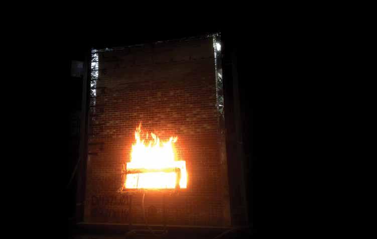
Actual Photo From Official NFPA 285 Test Knowing that a product has been tested & witnessed by some of the top laboratories in the country provides a very high level of peace of mind. The Pos-I-Tie® ThermalClip® was fully tested in 2014, as part of the CavityCompleteTM Wall System which passed NFPA 285 Fire Testing.
That’s GOOD news for Architects, Specifiers, & Contractors... BAD news for the competition!
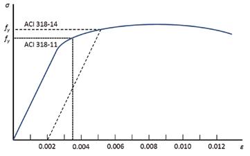
Figure 4. Definition of yield strength of high-strength reinforcement. Figure 5. Critical section for two-way shear around discontinued punching shear reinforcement (adapted from ACI 318-14 Figures R22.6.4.2a and R22.6.4.2b).
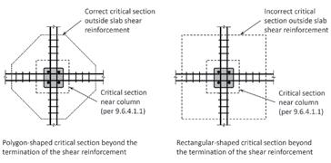
The stress in prestressing steel at the stage of strength, fps, can be calculated based on strain compatibility, or is permitted to be calculated in accordance with Eq. (20.3.2.3.1) for members with bonded prestressed reinforcement if the effective prestress is no smaller than one-half the tensile strength of the prestressing reinforcement. ACI 318-14 now requires that all prestressing reinforcement be located in the tension zone for Eq. (20.3.2.3.1) to be applicable. Chapter 22 – Sectional Strength For prestressed members, a new equation for the nominal axial strength at zero eccentricity, Po, has been introduced in Section 22.4.2.3. ACI 318-14 has also added Section 22.4.3.1, which requires that the nominal axial tensile strength of a nonprestressed, composite, or prestressed member, Pnt, be taken greater than Pnt,max, calculated by the new Eq. (22.4.3.1). In ACI 318-14, the two-way shear provisions are all expressed in terms of stress (vn, vc, vs, used in ACI 318-11 for slab-column connections subject to axial load and moment), never force (Vn, Vc, Vs, used in ACI 318-11 for slab-column connections subject to concentric axial load only). Section 22.6.4.2 now reads: “For two-way members reinforced with headed shear reinforcement or single- or multi-leg stirrups, a critical section with perimeter bo located d/2 beyond the outermost peripheral line of shear reinforcement shall also be considered. The shape of this critical section shall be a polygon selected to minimize bo.” The last sentence is new in ACI 318-14 (Figure 5). Chapter 25 – Reinforcement Details Two changes are made in ACI 318-14 Table 25.3.2 to eliminate the difference between the required tail extension of a 90-deg or 135-deg standard hook (6db in ACI 31811) and that of a seismic hook (6db, subject to a minimum of 3 inches). The 3-inch minimum requirement now applies to standard hooks as well. Mechanical or welded splices with strengths below 125% of the yield strength of the spliced reinforcing bars are no longer permitted. The associated stagger requirements have been deleted. Thus, there is no longer a need to specify “full” mechanical or “full” welded splices. ACI 318-11 referred to the 17th Edition of the AASHTO Standard Specification for Highway Bridges (2002) for the design of local zone reinforcement in post-tensioned anchorage zones. However, AASHTO is no longer updating the Standard Specification for Highway Bridges. Therefore, in Section 25.9.4.3.1, reference is now made to the AASHTO LRFD Bridge Design Specifications. Chapter 26 – Construction Documents and Inspection There was no direct counterpart to this chapter in ACI 318-11. The first paragraph of the Commentary to Chapter 26 gives a very good idea as to what the chapter is about: “…This chapter establishes the minimum requirements for information that must be included in the construction documents as applicable to the project. The requirements include information developed in the structural design that must be conveyed to the contractor, provisions directing the contractor on required quality, and inspection requirements to verify compliance with the construction documents. In previous editions of the Code through 2011, these provisions were located throughout the document. Starting with the 2014 edition, with the exception of Chapter 17, all provisions relating to construction have been gathered into this chapter for use by the licensed design professional. Construction and inspection-related provisions associated with anchors are in Chapter 17 and are called out within Sections 26.7 and 26.13, as appropriate.” There are some substantive changes made to the ACI 318-11 provisions covered in Chapter 26. The ACI 318-11 (Section 3.5.1) language “Discontinuous deformed steel fibers shall be permitted only for resisting shear under conditions specified …” has been interpreted to restrict other applications in which discontinuous deformed steel fibers could potentially be used. The wording has been improved to indicate that ACI 318-14 only addresses the use of deformed steel fibers for shear. Other applications are not prohibited, but rather fall under ACI 318-14 Section 1.4. ACI 318-11 Sections 5.3 – Proportioning on the basis of field experience or trial mixtures, or both, 5.4 – Proportioning without field experience or trial mixtures, and 5.5 – Average compressive strength reduction contained prescriptive requirements for mixture proportioning. These requirements are no longer found in ACI 318-14; instead, ACI 301-10, Specifications for Structural Concrete, is referenced from Section 26.4.3. Requirements for post-tensioning ducts and grouting have also been removed as being outdated. The Commentary now provides specification guidance.
Conclusions
Contrary to the widely held perception that in view of a complete reorganization of ACI 318-14, technical changes were held to a minimum, ACI 318-14 contains a number of significant technical changes, some of the most important of which are found in Chapter 18, Earthquake Resistant Structures, and Chapter 19, Concrete: Design and Durability Requirements. ▪
This article was originally published in the PCI Journal (March/April 2016) and this condensed version is reprinted with permission.
LOUISIANA SPORTS HALL OF FAME
& NORTHWEST LOUISIANA HISTORY MUSEUM
By David L. Kufferman, P.E.
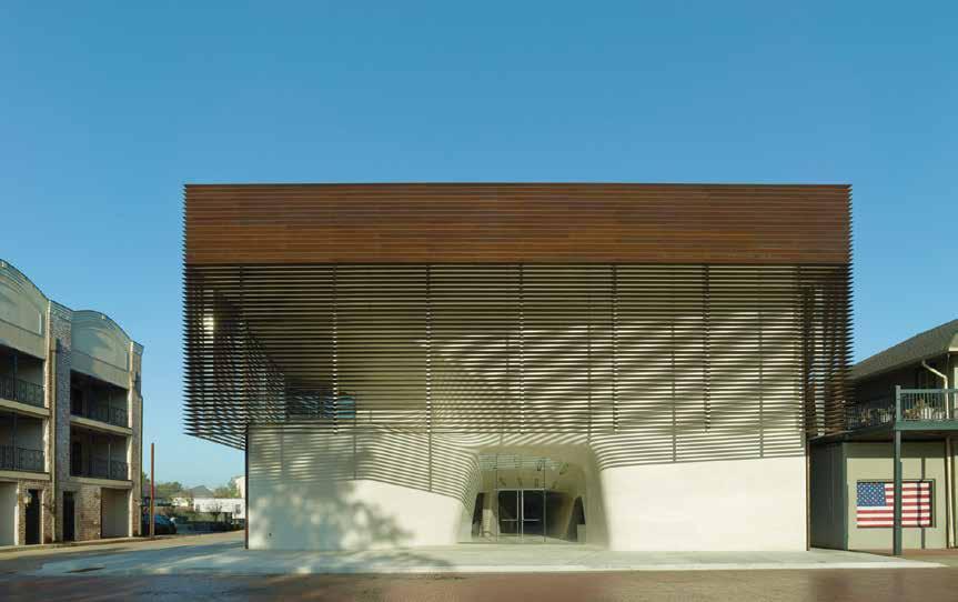
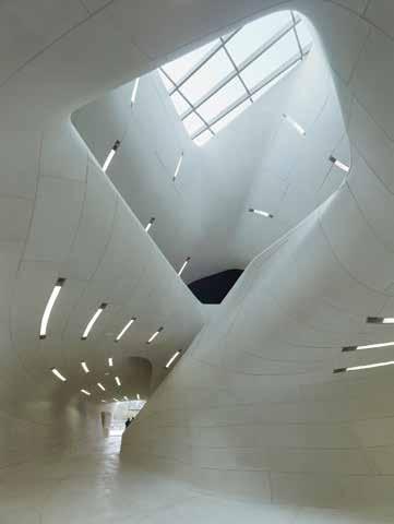
Figure 1. Cast stone entry façade. Courtesy of Timothy Hursley.
In the small Northwest Louisiana town of Natchitoches, there now stands a striking building to house both the Louisiana Sports Hall of Fame and the Northwest Louisiana History Museum. (Figures 1 and 2) The Hall of Fame, created in 1958, honors athletes who are either from Louisiana or have played for teams based there. Its roll of inductees includes football greats such as Y.A Tittle, Terry Bradshaw, and Archie Manning, basketball stars such as Pete Maravich and Shaquille O’Neill, and many other standouts from the sports world. The Northwest Louisiana History Museum examines how diverse groups of people, including the Caddo Indians, French and Spanish settlers, and free and enslaved Africans created the unique culture of the region. Natchitoches is the oldest municipality in the state, founded by the French in 1714. The Sports Hall of Fame had been housed in a section of Northwestern State University’s Prather Coliseum since 1971. In 2003, the Hall of Fame was accepted into the Louisiana State Museum system, which set the stage for the creation of a new museum building. The project was funded with a $12.6 million construction budget in 2007. Trahan Architects of New Orleans were ultimately selected to design the building. Construction began in 2010 and was completed in 2013. The Hall of Fame/Museum is a two-story box-like structure enclosing about 28,000 square feet. The structural system of the building is a braced steel frame with composite concrete metal deck slabs. The ground floor is a slab-on-grade. The building is founded on auger cast piles. Lane Bishop York Delahay, Inc. (LBYD) of Atlanta, Georgia was the structural engineer for the building frame. The most distinctive feature of the building is the expressive undulating cast stone surface which defines both its interior and exterior. The architect wanted the building to evoke the meandering rivers of
degrees of adjustability, and often ‘blind’ as well. In the end, over two dozen ‘typical’ panel connection types had to be developed, depending on 1) whether the panels were stacked, bolted up, hung, or some kind of hybrid thereof, 2) whether the panel was interior or exterior, and 3) whether the connection was accessible or ‘blind’. Still, many completely unique connections had to be developed on a case by case basis. As the original digital surface in the Trahan model was ‘panelized’ in five sequences by CASE Inc., the project’s Building Information Model (BIM) consultants, using CATIA CAD/CAM software, the Shaped Surface Support Steel (SSSS) design team took over. The ‘SSSS’ design team consisted of David Kufferman Structural Engineers working Figure 3. Complete Rhinoceros model of cast stone and SSSS. Courtesy of Method Design. jointly with Method Design, the cast stone support steel geometry consultants, Craft Engineering the region. David Kufferman Structural Engineers was awarded the Studio, the structural analysis consultants, and Total Global Steel task by Advanced Cast Stone, the cast stone fabricator, of designing Detailing, the steel shop drawing detailers. Kufferman worked the shaped surface supporting steel structure (SSSS) for the cast with Method Design to develop the structural geometry of the stone panels. supporting steel frame in digital space. Using the appropriate panel The cast stone surface can be described as a 1,051 piece three- connections developed by Kufferman, Method Design developed a dimensional jigsaw puzzle that weighs about 700 tons, with each digital model in Rhinoceros three-dimensional modeling software piece separately made according to its own unique, digitally created by creating automated steel framing geometry definitions using pattern, therefore having a different size and shape from any other Grasshopper, a graphic algorithmic editor that is tightly integrated piece. At the beginning of the design process, it was realized that with Rhinoceros. Such algorithms were developed based on prethe puzzle could only be properly assembled if all the pieces were liminary framing element shapes and their location parameters, as nearly perfectly made. Otherwise, the pieces would not fit together specified by Kufferman. Panel anchor type and locations were fully correctly. The task was further complicated by the fact that this defined, and this information was passed back to CASE so that massive three-dimensional jigsaw puzzle had to be supported by a final panel shop tickets could be generated for cast stone panel steel space frame. In turn, the frame had to be supported either by production. Kufferman and Method Design worked together to vary the ground floor slab-on-grade, which is essentially rigid, or by the such parameters until an acceptable frame geometry was obtained second-floor framing, which would deflect under load, thereby caus- that would minimize the number of complex mitered butt welded ing a change in the puzzle’s geometry as load is applied or removed. ‘kinks’, but without allowing steel framing elements to either get Again, if some panels moved too much, while others moved little if too close or too far from the back surface of the cast stone panels. at all, the pieces of the puzzle would no longer fit properly. A brittle Every single connective element specified by Kufferman was defined material like cast stone cannot tolerate much movement without in the Building Information Model by Method Design. Over 2,150 the risk of cracking. separate panel connections were needed for the project, with each Early in the design process, it was hoped that the great compressive connection providing support to any number of panels, ranging strength of the cast stone might be exploited through shell action, from one to four (Figure 3). but the overall surface was far too irregular to allow for this kind of The resulting ’SSSS’ frame was then analyzed under load using Robot, behavior to happen. This was only possible in cases where panels a three-dimensional structural analysis program. Method Design used could be stacked into a wall that was more or less vertical, though yet another plug-in program called Geometry Gym to convert the they still had to be tied back to the steel framing to keep them stable. Rhinoceros model into a Robot input file. Kufferman, in collaboraFar more often than not, the panels had to be fully supported by the tion with structural analysis consultants Craft Engineering Studio in steel framing hidden behind them. Indeed, movement connections New York City, refined the Robot models, modifying support and were required in nearly all panels, specifically to prevent shell action, connective conditions so as to best simulate what was to be expected since accumulating forces flowing from panel to panel through their in reality. After over-stressed or excessively flexible elements in the anchor bolts would have failed these bolts had the panels been fully model were beefed up, and under-stressed elements were lightened restrained. Ceiling panels that were close to horizontal could only be to reduce steel weight, the structure was reanalyzed. Once an acceptsupported by hanging them from the steel frame. Most other panels able SSSS was fully developed, the Rhinoceros model was updated, were somewhere between these two conditions and had to be bolted and converted into SDS/2, a steel detailing program, so that shop directly to the steel frame using connections with a large degree of drawings could be generated. adjustability to allow for the ever varying geometry. In some cases, Steel was fabricated and erected by Champion Steel of Louisiana connections were easily accessible for welding, but in other cases, and Commercial Metals Company (CMC) of South Carolina. A total the erection sequence would have made access to some connections station theodolite, that was digitally referenced to the BIM, was used impossible, so ‘blind’ connections had to be developed. In areas to locate steel during erection such that any point on the steel had to exposed to the weather, it was feared that hot fragments from field be within one-half inch of the specified location. The same system welding might damage the waterproofing below the connection, was used to precisely locate the cast stone panels as they were erected which necessitated fully bolted and galvanized connections with six by the installer, Masonry Arts. continued on next page
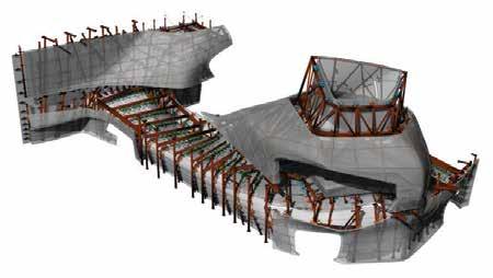
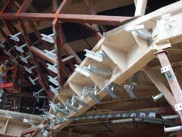
Figure 4. Exterior steel showing galvanized channel section ‘blind’ cast stone panel connectors. Light gauge metal framing of weather wall not yet installed. Courtesy of VCC. Figure 5. Atrium steel framing with one of two pre-deflection ballast tubs in the foreground. Courtesy of VCC.
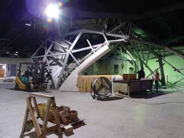
The precise specification, fabrication and erection of the SSSS became especially critical during the second sequence, which included all of the exterior cast stone panels. Since the panels were considered to act as a rain screen rather than a waterproof barrier, the steel elements had to be installed prior to the waterproofing system, which had to occupy the space between the cast stone and the SSSS. The panels could only be installed after the waterproofing was complete. This meant that the galvanized connection elements, to which the cast stone panels had to be bolted, as well as the galvanized stand-off tubes that penetrated the waterproofing, had to be precisely shop-welded to the SSSS frame, with no possible provision for field-modification afterward. Galvanized clips with long slotted holes and galvanized A325 slip-critical bolts had to be used to accommodate all tolerances. Open slotted holes were used for ‘blind’ connections (Figure 4). In the case of the final sequence, which was the cast stone surface defining the atrium and the monumental stair, concern was raised about deflections due to the fact that the SSSS that provided support for the 165 tons of cast stone in this area was completely carried by the second-floor framing. The Robot analysis of this sequence included the floor beams so that an accurate estimate of the deflections could best be achieved. It was indeed found that the overall flexibility of the system would lead to panel fitment problems if no compensating action was taken during panel installation, despite the fact that code mandated deflection criteria was easily satisfied. A structure that does not deflect under load is, quite simply, a physical impossibility. Theoretically, the only way to get the geometry perfect would be to pre-deflect the SSSS frame using ballast equal to the cast stone panels in both weight and distribution. Because of the practical problems surrounding the procurement and installation of 165 tons of ballast over about 500 connections, an alternative approximate means of pre-deflection was devised using two concentrated loads totaling 24 tons, hung from temporary frames. As panels were erected, panel positions were continuously monitored so that the pre-deflection loads could be reduced appropriately. This procedure successfully minimized the racking and distortion problems that were anticipated, while using ballast equal to only 15% of the final panel weight (Figure 5). The Louisiana Sports Hall of Fame opened to the public on June 28, 2013, at a gala to celebrate both the astonishing new building as well as the induction of basketball legend Shaquille O’Neill and tennis star Chandra Rubin, among several other outstanding athletes. Since then, the project has won numerous major design awards, including the 2015 American Institute of Architects (AIA) National Interior Architecture Honor Award, the 2014 Chicago Athenaeum American Architecture Award, the 2013 Architect magazine Honor Award, and the 2013 Interior Design magazine Best of Year Award. In 2013, Azure magazine named it the Top Project in the World. Not too bad for a small town museum in west Louisiana.▪
Project Credits
Client: State of Louisiana, Office of Facility, Planning &
Control Structural Engineer: LBYD Cast Stone Support Steel Engineer: David Kufferman, P.E. w/
Craft Engineering, NYC Architect: Trahan Architects, New Orleans Interior Designer: Lauren Bombet Interiors M/E/P/FP Engineer: Associated Design Group Civil Engineer: CSRS Geotechnical Engineer: GeoConsultants General Contractor: VCC Landscape Architect: Reed Hilderbrand Associates BIM Manager and Technology Consultant: CASE Cast Stone Support Steel Geometry: Method Design Acoustics: SH Acoustics Waterproofing: Water Management Consultants & Testing
David L. Kufferman, P.E., is President of David L. Kufferman Structural Engineers, Fairfield, CT. He can be reached at david.kufferman.pe@sbcglobal.net.
Field Adjustable
Can be field trimmed and drilled
Shear Transfer Plate for Header/Top Plate Attachment
Ships with every wall and installs with nails

More Applications
Residential, multi-family and light-frame commercial construction
EASY
TO SPECIFY INSTALL INSPECT
Stronger Wall
Narrow panel widths have higher loads
Code Listed
ICC-ES ESR-2652 and City of L.A. RR 25730 evaluated to the 2015 IRC/IBC
Easy to Install
Front, back and side access for easy installation and inspection


The new Strong-Wall® Wood Shearwall has arrived and is better than ever. Standing up to 20 ft. tall, the new walls have significantly higher allowable loads than our original https://widendtp.com/ssttoolbox/uqnjmzfgnn/metal_plate_look_36percent.psd?res=proxy prefabricated wood walls and are now much easier to install and inspect. With visible front, back and side access for anchorage attachment, and a simplified top-of-wall connection, they can be installed before or after framing. Learn more about our new high-performance, field-trimmable Strong-Wall Wood Shearwalls (WSW). Call (800) 999-5099 and visit strongtie.com/wsw.


Restoring the
FOUNDATION OF JUSTICE
By Thomas E. Forsberg, P.E.
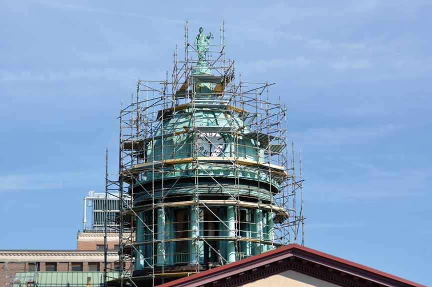
Figure 1. Dome shrouded in a scaffolding tower.
The foundation of Justice in the County of Lancaster, Pennsylvania is once again stable and poised for another century of oversight. Justitia (the Statue of Lady Justice) is re-perched on a new structural framework atop the County courthouse dome. The 1850s-era wood-framed dome structure suffered the primary long-term effect of water intrusion: rot. A broad and vague term, “rot” defines merely a symptom, but does not convey any degree of extent. Atop the courthouse dome, the rot can only be described as severe.
History
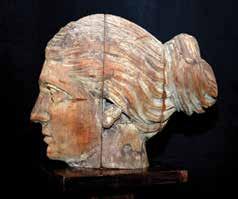
the County retained Schradergroup Architecture, LLC, to thoroughly examine the roofing and dome structure, develop a report describing the conditions, and recommend corrective work to restore and preserve the dome. Further, the County decided to remove and restore the Statue. The current copper version, installed in the 1920s, is the second Statue to grace the top of the courthouse dome; the original was made of wood (Figure 2). This work required a scaffold tower around the dome reaching nearly 140 feet above the sidewalks and streets below. Fortunately for the team, the scaffold would facilitate the examination and subsequent restoration work (Figure 1).
When the roof on a historically significant piece of your county’s architecture leaks, what do you do? Of course, you patch it. And many attempts were made to do exactly that. However, there is a point where the “patch method” no longer works; when you’re repatching patches, it’s time for a better solution. In 2014, the County’s Facilities Management department decided that they needed a new approach. At nearly 80 years of age, the copper roofing was, literally, wearing thin. Too many applications of incompatible materials aimed at preventing ongoing water infiltration were doing more harm than good. Prompted by observations of water leaks and signs of damage to the wood framing,
Examination
Able to proceed with a hands-on examination of the exterior roofing surfaces, the inspection team quickly observed that the copper skin was in poor condition along with evidence of an entire system failure: pan seam overstress, material deterioration, loose and missing fasteners, leaks, and failed repairs resulting from inappropriate patching materials applied to the copper. By its geometry and construction, the upper portion of the dome’s interior was inaccessible for visual inspection. However, based on the overwhelming evidence of leaks and deterioration in the copper roofing system,
the examination continued with invasive probes to assess the underlying structure. There was no question whether there was any structural damage, only the extent to which the damage had reached. The evidence from several probes overwhelmingly showed that the dome structure had been compromised. Wood decking was rotted so severely that it could not retain the fasteners that held the copper roofing on the dome nor maintain its connection to the structural framework. Removing the Statue happened concurrently with the examination and evaluation of the dome. In November 2014, the Statue was secured into a steel-framed lifting cage, hoisted from atop the dome, and transported to an off-site studio to begin its makeover. With the Statue out of the way, the upper reaches of the dome structure were exposed and accessible for examination. The final evidence required to conclude the examination was observed, and corrective work was recommended (Figure 3). In a presentation to the County’s decision-makers, the final conclusion of the team’s report was summarized:
Movement in the excessively large copper pan’s overstressed seams caused tears and open joints. Further, repairs made with incompatible materials have failed, exacerbating long-term water intrusion and the ensuing structural damage: eroding roofing fasteners and rotting the wood decking and structure. Given the conditions of the roofing system and structural deficiencies, there was no choice but to undertake a wholesale restoration: remove all the copper, repair/replace all of the damaged structural framing, replace the wood deck, and install a new roofing system.
Documentation
One of the greatest challenges in this type of work is to know where and when to strike a balance between probing for more evidence and data versus making assumptions and estimates about the work that will need to be done. Perhaps the most successful aspect of this project was the method by which the team worked together, examining the structure and systems, defining what was known, and making a list of unknowns with associated worst-case and worst-cost outcomes.
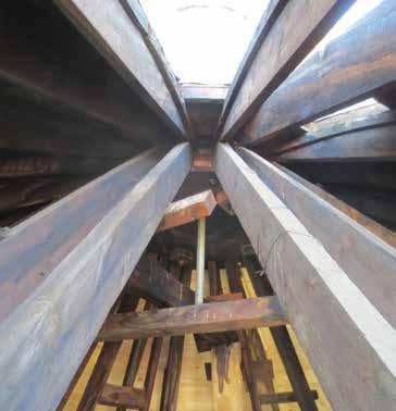
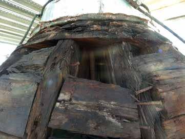
Figure 3. Conditions of wood rot at top of dome structure, underneath statue.
In the end, the Owner had the equivalent of a guaranteed maximum price to perform the work, even though many pieces of the scope were still unknown. Architects and engineers usually manifest their work through the development of construction documents. After all the behind-thescenes work is done – research, calculations, coordination, etc. – plans, elevations, sections, and details are developed and organized as an instruction manual. And by following those instructions, builders bring projects to fruition. For this project, however, developing an accurate set of construction drawings, while not entirely impossible, was both impractical and unnecessary; impractical because of the convoluted and variable nature of the existing construction, and unnecessary for the exact same reason. Therefore, the team agreed that the documentation process would take an as-built approach and be developed as a collection of photographs, field notes, and sketches to reflect the discoveries and corrective work that occurred along the way. continued on next page
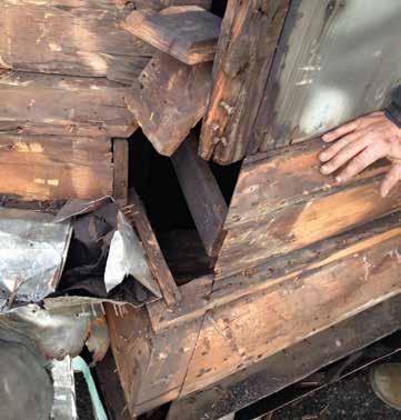
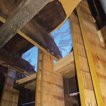
Figure 6. Transfer posts to facilitate removal and replacement of compression ring.
Simple schematic drawings were used to label various elements such as dome bays, trusses, tension and compression rings, and outriggers. However, these documents were used for establishing consistent nomenclature, tracking the progress of work, and documenting locations of various field repairs, not for bidding purposes or to accurately define the work scope.
Restoration
Work began on Monday, December 8, 2014 – not the best time of year to start an 8-month roofing project in the Northeastern US. While there was a broad understanding of how this project would proceed, the team anticipated a wide range of conditions and the need for real-time, on-the-fly review and resolution. Standard details did not apply here. Moreover, to the greatest practical extent, new structural elements required for either repair or replacement work had to be made on site. With an open roof during winter months, there was no time for a typical shop drawing and fabrication process. The main dome trusses – there are twenty-four in all – were assembled using several pieces of heavy-timber framing. Despite the poor conditions of the wood decking, the underlying structure was largely unaffected and in very good condition (Figure 4, page 35). There were still a number of repairs to be made on a localized basis, but no primary structural elements needed to be removed and replaced in entirety. Removing the copper roofing and wood decking unveiled all of the hidden structural elements and conditions. On Day 1, the team observed cracks and rotten wood in one of the trusses. Fortunately, having both the designer and contractor standing on the scaffolding looking directly at the problems, they were able to talk through various ideas and determine a workable solution that could be implemented immediately. There are four clocks on the main dome, one facing in each of the four cardinal compass directions. Each clock stands proud of the main dome surface and is covered on the top and sides by a dormer-like structure. These elements suffered significant damage from water infiltration, particularly the structural framing under the clocks (Figure 5, page 35) and the main dome compression ring that supports the dome trusses. The compression ring, constructed from multiple layers of heavy timber with offset splices and thru-bolted connections, is critical to the structural integrity of the dome. Repairing it meant removing the rotted wood and rebuilding entire segments. Of primary concern was the relief and transfer of dome truss loads around the damaged portions of the ring. This required a series of transfer posts connected to the structural framing above and below the ring. These elements facilitated unfettered access to the ring for corrective work (Figure 6). Perhaps the worst conditions occurred at the top of the dome. The compromised condition at the base of the Statue allowed years of water intrusion. The wood framing quite literally crumbled to shards as it was removed. However, enough integrity remained to allow the team to document geometry and element sizes to ensure reconstruction occurred in a like manner. Figure 7 illustrates the condition of the original wagon-wheel
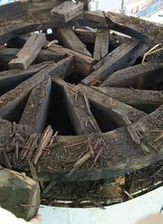
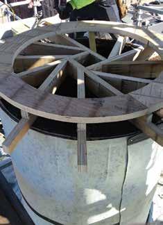
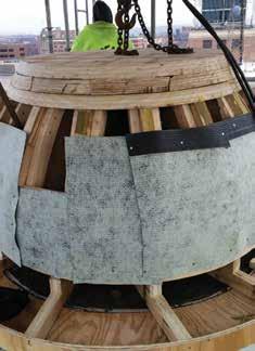

Figure 10. Completed restoration of the Lancaster County Courthouse Dome.
Thomas E. Forsberg, P.E., is Principal – Structural Engineering at Schradergroup Architecture, LLC, with offices in Pennsylvania, Maryland, and Delaware. Thomas can be reached at tforsberg@sgarc.com. frame underneath the dome cap, and Figures 8 and 9 show its reconstruction progress and the new framework to support the Statue. Not one leak occurred during the restoration of the Lancaster County Courthouse Dome. Working through winter months of rain, snow, sleet and wind is a testament to the quality, craftsmanship, and pride of the restoration crew. A revitalized Lady Justice is once again overseeing the Courthouse, and she has a new weather-tight connection between her base and the top of the dome. Since the connection was the worst flaw in the roofing system, considerable care was taken to ensure the integrity of the joint so that it will no longer be a source of water infiltration. Restoring the dome was accomplished in the manner that every owner desires: ahead of schedule, under budget, and without any change orders. The process of real-time tracking of work and budget allowed the County to perform additional maintenance and repairs on portions of the structure that were not part of the original scope. In the end, this piece of the County’s history is ready for another century of service (Figure 10).▪
Project Team
Owner: County of Lancaster, Pennsylvania Restoration Team: Lancaster County Facilities Management Staff Architect & Structural Engineer: Schradergroup Architecture,
Lancaster, PA Roofing Consultant: Tricon Building Services, Lititz, PA Roofing Contractor: Ream Roofing, York, PA Supplier: The Garland Company Conservator: Materials Conservation, Philadelphia, PA
ADVERTISEMENT–For Advertiser Information, visit www.STRUCTUREmag.org