43 minute read
Structural Design


design issues for structural engineers
Apart from the weight, there is nothing lightweight about lightweight struc tures. With traditional structures, the loads are resisted by the stiffness in the beams, columns, and walls; with tension-only and compression-only structures, the overall form of the structure becomes critical. Get the form right and the structure can span huge distances with minimal material; get the form wrong and you are in trouble. “Students … learned that nonlinear systems were usually unsolvable, which was true, and that they tended to be the exception – which was not true.” James Gleick (1988) We can all remember, in structures 101 lectures, when we were told that a beam could have a pin at one end and a roller at the other, but it could not work if you added a pin in the middle as well. This is true if you want to keep the analysis linear, and not create any horizontal reactions, but is a hopeless approach if you want a bridge to cross 1.5 miles of Why It’s Good to be a Lightweight river. The linear approach just will not work; it’s time to take a nonlinear approach. Many building structures are linear, or at least near Geometrically Nonlinear enough to not worry about nonlinear effects. Structures The beams and columns are kept within tight deflection limits and they tend to behave in By Peter Debney, BEng(Hons), CEng, MIStructE a linear way. The truth is that all structures are nonlinear. It’s just that the simpler linear analysis usually gives answers that are close enough for the majority of engineering design. So what makes nonlinear different from linear analysis? One of the most important things to remember is that with linear analyses you establish equilibrium of the forces on the original Peter Debney, BEng(Hons), geometry, but with a nonlinear analyses you get CEng, MIStructE, is a Chartered equilibrium of the forces on the deformed geomStructural Engineer and etry. The problem is, you don’t know what the software specialist with over 20 deformation is until you have resolved the forces years’ experience specializing in and you cannot resolve the forces until you know computing applications, half of the deformed shape. All nonlinear analyses thus those in practice and the rest in requires a certain amount of iteration. engineering software, whether BIM, analysis or design. He is an application specialist for Oasys, Cables concentrating on structural and While linear structures resist loads with bending crowd simulation software. stiffness, lightweight nonlinear tensile structures work by deflecting until the forces are in balance. Take a look at a very simple example: a cable supporting a single point load at its centre. For extra simplicity, ignore the self-weight of the cable, strain hardening and strain limits. Concentrate purely on the point load and how the cable
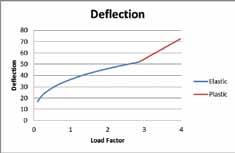
The online version of this article contains a list of subject sources. Please visit www.STRUCTUREmag.org. responds to it. Before the load is applied, the cable is straight and unstressed. When the load is applied, the cable cannot resist: it has no bending strength, so it starts to deflect. As it deflects, it begins to stretch and tension is induced. As the cable is no longer perpendicular to the load, there is therefore a vector component of that tension that resists the load. As the deflection increases, so does the induced tension and angle until the deflection reaches the point where the load is exactly balanced by the parallel vector components in the cable tension (Figure 1). This structure is nonlinear, as it has to deflect to carry the load. Don’t forget that all structures have to deflect to carry load, but nonlinear ones such as this have to move a significant distance to reach static equilibrium. Force/Action → Acceleration → Deflection + Resistance → Strain → Stress → Reaction → Equilibrium The nonlinearity in the system is seen by plotting load against deflection (Figure 2). Note that the final axial force in the cable is totally dependent on its final angle. Such a structure is also very sensitive to the support stiffness: as the supports move in, the deflection increases, as does the angle of the cable. This will result in a larger deflection but a lower stress in the cable. If the two parts of the cable become parallel (either by infinite deflection or the more useful option of moving the supports together until they touch), the axial force will be equal to exactly half the applied load. Note also that there is minimal lateral resistance to movement. You have made a pendulum. Conversely, we can reduce the deflection by applying a pre-stress to the cable, so that the higher tension generates the required resistance at a shallower angle. In theory at least, you could achieve zero deflection with infinite pre-stress. Practical structures fall between these two extremes. The picture starts to get more interesting when section and material properties are considered. Initially, one might surmise that the deflection of the cable is independent of the cable stiffness, but the reality is that tension will build faster in a material with a higher stiffness and thus reach equilibrium at a lower deflection. There is also the structure’s behaviour when the stress in the cable reaches the material plastic yield limit: the cable might yield but the structure will still carry the load. Even though the cable cannot carry any more stress, the load is carried by a combination of the stress and the angle of the cables, so any further increase in load results in a much higher deflection. In theory, the cable can carry a load of twice the yield strength of the cable. However, that would require the cable to deflect to infinity; the strain limit will have been reached long before that. So with one point load on a cable you get a V shaped result. Adding more point loads or making the load uniform will pull the cable into the classic catenary shape, familiar to us from suspension bridges.
Figure 1. Diagram of defl ection and load.
Figure 2. Load-defl ection.
Cable Nets
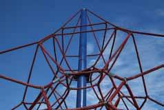
A single loaded cable, such as a catenary, is stabilized out-of-plane by gravity and possibly additional factors such as the bridge deck. However, such structures are still vulnerable to sway, whether induced by wind or pedestrians. A solution to this problem (though not normally for bridges) is to have cables going in multiple directions, so sway in one direction is resisted by cables at other angles, providing what is called a cable net. Th ese are actually common structures in nature. It is likely that there are tens if not hundreds in your house and garden, spun by spiders (Figure 3). If such a cable net is horizontal and loaded, it will defl ect down with an essentially catenary shape, giving resistance to gravity loads. Th ere is still a problem: what about uplift forces on such a cable net if clad? Suction would be resisted purely by the self-weight of the structure, which is minimal. As catenaries are good at resisting load in the direction of the curve, the solution is to have the cables in one direction curve down to resist gravity loads, and those in the other direction curve upward to resist suction loads. Th is double-curved hyperbolic surface is characteristic of many cable nets and all engineered fabric structures, as the shape naturally gives stiff ness in all directions. Th e alternative is to provide cables in all directions, which might not give a practical roof but makes for great climbing frames (Figure 4).
Velodrome
So what does such a double curved surface look like? An excellent example is Expedition’s award winning Velodrome for the London 2012 Olympics, famous for its “Pringle” shaped roof. Beneath
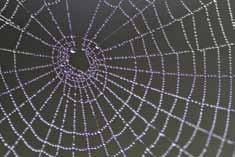
Figure 3. Spiders web.
the 16,146 square yard (13,500 m2) cladding lies a cable net, effi cient enough to keep the total weight down to a mere 12 pounds per square foot (60 kg/m2). Despite its lightness, the roof is still stiff enough to keep the lighting from shaking, something that the cyclists would fi nd extremely distracting. Th e shape also has the advantage of minimizing the volume of the space and thus reduce heating and cooling loads while at the same time maintaining audience sight-lines. On the other hand, spiders instinctively make their webs in a single plane, giving them
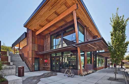
DUVALL LIBRARY, DUVALL, WA Figure 4. Climbing frame.
a fl exibility undesirable in most engineered structures. From the spider’s point of view this is exactly what they need, as they are, like safety nets, designed to catch and absorb the energy from fast moving objects. A double curved spiders web may be too stiff and thus allow fl ies to bounce off before the glue has a chance to work. As tension structures are very sensitive to movement at the supports, the Velodrome roof needed a stiff steel compression ring, which was in turn borne by raking trusses that also supported the seating. Th e trusses in turn were rigidly mounted on the concrete
Seattle • Tacoma • Lacey • Portland • Eugene • Sacramento • San Francisco • Walnut Creek • Los Angeles • Long Beach • Pasadena • Irvine • San Diego • Boise • Phoenix • St. Louis • Chicago • New York
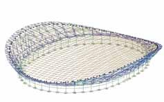
Figure 5. GSA model of Velodrome. Courtesy of Expedition Engineering Ltd.
base structure. Designers used GSA Analysis modeling software (Oasys) throughout the design process, from form finding the cable net to static analysis to checking the vibration characteristics of the completed building (Figure 5).
Forming a Hyperbolic Surface
Unlike most double curved surfaces, hyperbolic surfaces have a curious property: you can make them entirely out of straight lines. We are all familiar with single-ruled surfaces such as cylinders, where you can define the surface with a series of straight lines all going in the same direction. Hyperbolic surfaces are double-ruled surfaces, meaning that they are formed from two series of parallel lines. The classic version of this is the hyperbolic paraboloid, or hypar for short, which you can form by twisting a rectangular plane (Figure 6). Although the Velodrome roof is a hyperboloid, it is slightly different as the cables were at 45° to the ruled surface (Figure 7). Both options have the same surface and about the same quantity of material, but the latter is twice as stiff due to the curved profile of the cables, halving the deflection. This means that the longer span cables actually deflect less. Rigid hyperboloid structures were first used by the Russian engineer Vlaadimir Shukhov in the 1890’s with his lattice tower in Polibino, Lipetsk Oblast. He is most famous for his Shabolovka Radio Tower. The form has been subsequently used for architectural towers such as Zhou Ruogu and the Kobe Port Tower (Figure 8), but also to give the humble cooling tower its buckling resistance. Hyperboloids are not the only form of double-curved surface used with lightweight structures. The basic forms also include the Conic and the Barrel Vault (Figure 9). There is also the dome, which will be discussed in Part 2 of this article.
Fabrics
Figure 6. Hyperbolic paraboloid double-ruled mesh.
Element list: P1 Scale: 1:17.63 Deformation magnification: 4.000 Node Loads, Force: 0.5000 kN/pic.cm
Outputaxis: global Resolved Element Translation, |U|
Outputaxis: local 90 mm 80 mm 70 mm 60 mm 50 mm 40 mm 30 mm 20 mm 10 mm mm Case: L1 Case: A1 : Analysis Case 1
Contour case
z
y x
Figure 7. Hyperbolic paraboloid mesh.
Element list: P2 Scale: 1:20.65 Deformation magnification: 10.00 Node Loads, Force: 0.5000 kN/pic.cm
Output axis: global Resolved Element Translation, |U|
Output axis: local 90 mm 80 mm 70 mm 60 mm 50 mm 40 mm 30 mm 20 mm 10 mm mm Case: L1 Case: A1 : Analysis Case 1
Contour case
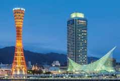

Figure 8. Shabolovka Tower, Zhou Ruogu, Kobe Port Tower.
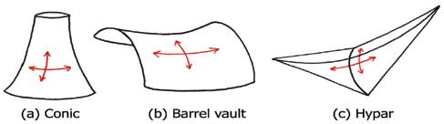
Figure 9. Hypar, Conic, and Barrel forms.
the most important differences is that fabrics are woven while cable nets tend to be layered. This gives rise to the fabric’s warp-weft interaction, which means that when you tension one direction more than the other, the fibres in that direction straighten and increase the kink in the other. This gives fabrics both an unusual stressstrain relationship and Poisson’s ratio. Fabrics are thus sensitive to the balance of pre-stresses in the two principle directions; the fabric will wrinkle as a whole if the pre-stress is much higher in one direction than the other (Figure 10).
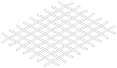
Figure 10. Fabric weave.
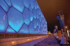
Figure 11. 2008 Olympic Aquatic Centre, Beijing. Courtesy of Arup.
Because of this arrangement, fabrics are principally stiff in the warp (principle fibre) and weft/fill (secondary fibre) directions, and have minimal stiffness diagonally. Coating the fabrics can increase this stiffness, but the low shear stiffness does aid the fabric’s ability to twist into the required double curved surfaces.
Foils
A step further on from fabrics are foils, which are isotropic plastic sheets made from materials such as ETFE (ethylene tetrafluoroethylene) and in use on iconic structures such as The Eden Project and Beijing 2008 Water Cube (Figure 11). Foils are generally used in inflated pillows, so each cladding panel is actually two or three separate layers supported by pressurized air. Wind loads on one surface are carried through the contained air to load the opposite face, so the whole remains in tension. The air can be heated to prevent snow loads. Unlike fabrics, foils have a good shear strength; they have to yield under load to achieve their final form, though form finding and determining the correct cutting patterns goes a long way to minimize this.
Edge Conditions
Because the pre-stress is crucial to ensure the tension and hence stability of fabrics, it is important to consider how to achieve this pre-stress. Fabrics require an edge support, which can either be solid, such as a beam, or flexible, such as a cable. With flexible edges, the cable’s curvature (or “set”) is dependent on the balance in the pre-stress between the cable and fabric. Apart from structural considerations, this set has quite an impact on the aesthetics of the fabric structure. The balance of the pre-stress in the fabric is also crucial and must be in harmony with the fabricated surface. A correctly tensioned fabric will be smooth, as can be seen in Arup’s Marsyas sculpture at the Tate Modern in London. Unbalanced tensions will cause wrinkles in the surface, known as Heugen’s Tension Fields (Figure 12).
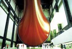
Figure 12. Masyas. Courtesy of Arup.
Munich 1972
The modern science and engineering of fabric structures was pioneered by Frei Otto, with his roof to the Munich Olympic Games being a major landmark in the industry. In rejection of the heavy wartime architecture of Nazi Germany, Otto aspired to make modern architecture as light as possible, in both senses of the word. The Munich roof achieved this by using both a minimum of material and maximum glazing (Figure 13). Frei Otto’s seminal work has continued to inspire and influence Olympic architecture. While the end effect is quite different, Mott MacDonald’s 2012 Shooting Gallery façades in London are based on exactly the same principles. Otto and his team needed to determine the geometry using physical models, with careful measurements feeding into hand calculations. Mott MacDonald, on the other hand, was able to use Oasys GSA for both the form finding and subsequent static analysis.
Tensegrity
So far we have looked just at tension structures, but now let’s start to mix in compression with the rather interesting group of structures known as Tensegrity. Buckminster Fuller coined the term as a portmanteau of Tension and Integrity, and described them as an “island of compression in an ocean of tension” (http://bfi.org). Rene Motro went a little further when he said that,
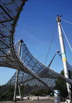
Figure 13. 1972 Olympic Main Stadium, Munich.
“A tensegrity is a system in stable self-equilibrated state comprising a discontinuous set of compressed components inside a continuum of tensioned components.” And artist Kenneth Snelson (http://kennethsnelson.net) went further still with “Tensegrity describes a closed structural system composed of a set of three or more elongate compression struts within a network of tension tendons, the combined parts mutually supportive in such a way that the struts do not touch one another, but press outwardly against nodal points in the tension network to form a firm, triangulated, prestressed, tension and compression unit.” Now we see tensegrity at work in superb structures like Brisbane’s Kurilpa Bridge (Figure 14). It’s a cantilever beam, but where is the compression flange? Each element is either in pure tension or pure compression (ignoring the small bending on the struts from the selfweight), so the load path is not conventional. Like cable nets, pre-stress is essential to the stability of these structures to give them sufficient stiffness. You can make the simplest
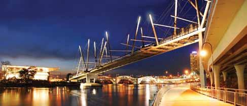
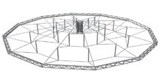
Figure 15. Tensegrity units.
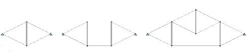
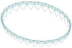
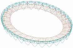
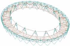
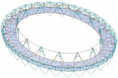
tensegrity work with just one strut and four cables (Figure 15a) or slightly more complex with two struts (Figure 15b). You can then start to combine these basic units to create more complex forms (Figure 15c). While these are stable in plane, they are unstable out of plane, so you will need additional cables or a full wheel (Figure 16). With a suitable compression ring, tensegrity structures have the ability to cover huge spaces such as stadia with minimal weight, usually by forming inscribed hoops, each one supporting the next. There are two classic forms to tensegrity roofs, known as the Geiger, where the cables are arrayed radially, and the Fuller, which is triangulated for improved stiffness.
2012 Olympic Stadium
An excellent and rather subtle version of the tensegrity roof is Buro Happold’s 2012 Olympic main stadium. Here the fabric infill panels disguise the boldness of this structure, with a single main cable loop tensioned and supported by radial cables from the steel frame. This cable, in turn, supports the 14 lighting rigs, each weighing 50 metric tons. These rigs are stabilized by back stays and a tension ring of their own (Figure 17). The programme did not allow for complete scaffolding of the compression ring, which was not stable until it was complete, so each stage in the erection sequence required separate GSA analyses to ensure stability and also to determine the locked-in stresses to take into the next stage. Further analyses were also required
Attention Bentley Users
Have you received your automatic quarterly invoice from Bentley? Would you like to reduce or eliminate these invoices? Use SofTrack to control and manage Calendar Hour usage of your Bentley SELECT Open Trust Licensing. Call us today, 866 372 8991 or visit us
www.softwaremetering.com
for each stage in tensioning the cable hoop, and then erection of each lighting rig and the fabric roofing (Figure 18).
Conclusion
Though their lower stiffness or deflection requirements do not make them suitable for every application, lightweight nonlinear structures already enable us to span huge distances with minimum materials. Part 2 of this article will look into the world of compression-only structures.
Figure 16. GSA tensegrity roof. Courtesy of Arjan Habraken, TU Eindhoven.
Acknowledgements
My thanks go to Matthew Birchall and his team at Buro Happold for the information on their 2012 Olympic Main Stadium. My thanks also go to Andrew Weir at Expedition for the information on their 2012 Olympic Velodrome, the various engineers at Arup that I have worked with over the years, and especially to my colleagues at Oasys for both creating the GSA software and for answering my many questions.▪
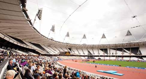
Figure 17. London 2012 main stadium. Courtesy of ODA.
Get there quicker

with Simpson Strong-Tie® CFS Designer™ software
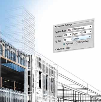


When designing cold-formed steel structures, you want a software program that is easy to navigate, versatile, and saves time by automating product selection and complicated design provisions of AISI. The new streamlined CFS Designer™ software by Simpson Strong-Tie does all of that and more. By shifting between design tools, you can model beams up to three spans and automate the design of wall openings, shearwalls, floor joists and roof rafters. All models are saved in a single file and output is saved as a PDF. To test drive CFS Designer, call your local representative at 800-999-5099 or visit www.strongtie.com/CFSDesigner to learn more.

©2014 Simpson Strong-Tie Co. Inc. CFSDESIGN14

“Not Just Another Dome Idea”
Micro Tilt-Up Construction for Super Low Cost Structures
By Matthew Brand and Thomas Tailer
Overview of Cementitious Materials Used
In this article, the term “cement” was used throughout, referring to various cementitious materials. The first Dome was built with a standard non-structural mortar mix that can be purchased at any retail home improvement store. The panels can be fabricated with any number of cementitious mixes, including grout, mortar and concrete. The second Dome is under construction using a grout mixture with excellent results. Additional materials will be tested in conjunction with the carpet in the future.
Every year approximately 160 million people are affected by natural disasters, with poverty identified as a major contributor of vulnerability to catastrophic events (WHO 2014). In addition, 4.7 billion pounds of carpet are discarded each year, accounting for 2% of all waste generated in the United States, with only 3.8% of the materials recycled (EPA 2012). The objective of this project was to design a low cost, high strength structure incorporating used carpet as a major structural component. Thomas Tailer, a local retired physics teacher, along with engineering students at the University of Vermont, designed and built a prototype dome structure in the shape of a truncated icosahedron. The goal of this project is to provide a safe, economical shelter intended to help people in the poorest communities in the world to survive natural disasters.
Construction Methods
The Dome’s design objectives include simple construction, minimal material use, and utilizing locally available materials and labor. Construction does not require sophisticated calculations, measuring devices, or tools. The goal was to achieve a fabrication tolerance of +/- 0.25 inches during the design process; however, during assembly, misalignments of up to three inches occurred while maintaining
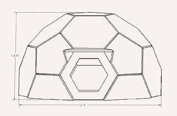
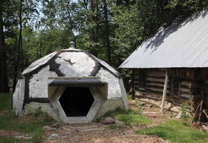
Figure 1. Completed structure. Courtesy of Meghan Holland. structural integrity. The Dome’s span is fourteen feet and reaches seven and a half feet in height (Figures 1 and 2). 2- by 4-inch wire mesh fence, laid eight inches within the panel joints, connects the individual panels together.
The Dome was designed by Thomas Tailer of Essex, Vermont using a compass to achieve the desired angles during planning and construction. The forms were placed on flat ground and lined with scrap plastic to hold the cement. The bottoms of the forms were lined with masonry cement by semi-skilled laborers, as seen in Figure 3. A carpet-cement laminate was constructed using two layers of carpet reinforcement surrounded by cement, with 14 gauge galvanized fencing wire bonded to the cement extending four inches out of individual panels to provide the panel connections (Figure 4). The carpet reduces the amount of cement necessary to make the panels, and also acts as tensile reinforcement. During loading events, the carpet will deform elastically; after the event occurs, it will have a tendency to return to its original shape. Each panel takes the shape of a pentagon or hexagon, weighing approximately 100 to 240 pounds, with a thickness of one and a half inches and with a side length of thirty inches.
The Dome assembly uses a layering technique with three steps of construction. The first step starts at ground or base level, and connects the panel edges to each other by twisting together the protruding wires. The second step requires cantilevering panels from the ground level panels and temporarily supporting them until three sides can be wired to the structure as displayed in Figures 5 and 8 (page 36). After the supported panel is wired into the structure, the temporary supports can be removed and used in attaching the next panel. The center piece is lifted into place by the use of temporary cribbing in the center of the dome. The temporary supports and cribbing are removed after all pieces are connected. Masonry cement is added between the joints, acting as a waterproofing feature and a reinforcing structural element. In addition, it prevents the wires from untwisting during large loading events. The Dome comfortably fits nine people (Figure 6, page 36), and would provide adequate shelter from extreme weather events. A chimney, stove, and external vent inserted into the structure allow for a cooking area, ventilation, and a heat source.
A team of students from the Governors Institute of Vermont and the University of Vermont’s Engineers Without Borders Chapter assembled the Dome. The students were unfamiliar and unskilled in construction. It took approximately 100 person hours to construct and assemble the panels and their forms. However, a semi-skilled team of laborers with greater strength, or laborers with more experience using the system, could likely fabricate a dome in 50 person hours. The material cost of the structure is approximately US $200, with the major cost being masonry cement.
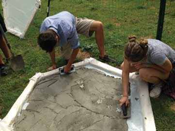
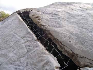
Figure 3. Panel formation of first layer. Courtesy of Hannah Marshall. Figure 4. Attachments between the panels before addition of masonry between joints. Courtesy of Megan Strand-Jordan.
Construction Challenges
Numerous challenges arose during construction of the Dome, mainly during the assembly of the panels. The first major problem emerged while trying to close the circular base of the dome. The base would not completely close due to misalignment, and the panels were extremely difficult to adjust by hand. Closure of the bottom panels was needed before the second level of panels could be placed. Construction completely stopped until the issue was resolved. A system of levers was designed to wedge the base into place and allowed the first layer to close. In order to avoid construction delays, future designs will feature the construction of a foundation before interlocking the base panels to ensure closure. The weight of the top panel was a major issue during the assembly process. The panel’s thickness made it much heavier than other panels used. Styrofoam aggregate added to the cement mixture was not successful in substantially reducing the weight of the panel. This issue required the assembly of cribbing in the interior of the Dome to support the top panel while it was wired into the entire structure (Figure 7, page 36). The top panel rose slightly higher than the total height of the structure and was lowered onto the lightly supported second level panels by removing part of the cribbing to allow for the final wire attachments. With the roof panel in place, the structure achieved the rigidity needed to stand unsupported. To avoid this situation in future construction, designs will use smaller panels that weigh no more than 100 pounds. Significant problems with the structural integrity of the panels arose during construction of the second level. A hexagonal panel cracked in half during transit from the mold to the structure because material shortages forced the use of subpar carpet during construction. The panel was severely damaged as an individual piece, and could not support its own weight. The integrity of the entire structure was called into question as a result of this panel failure. With winter fast approaching, entire replacement of the panel was not possible. The damaged panel was subsequently attached to the dome with the crack oriented vertically. It was believed at the time that the structure’s strength resides in its edges, and that it was unlikely that a single cracked panel would cause the failure of the entire structure. In addition, the placement and orientation of the crack took advantage of the compressive lateral forces provided by the dome shape to negate the damage done to the panel by the crack. The dome has remained standing successfully for one year with its structural integrity intact, surviving significant snow loading during the harsh 2013-14 Vermont winter and repeated freeze thaw cycles, with no apparent signs of structural damage or deterioration.
Applications/Conclusion
Conventional construction systems for housing in third world countries use reinforced masonry that is expensive both environmentally and economically, and often do not provide enough protection from earthquakes and other natural disasters. The goal of this project was to develop a new system using resources that are currently wasted or underutilized to help provide shelter to the world’s poorest people severely affected by natural disasters. The system and construction process has application to many other structures that could be built at reduced costs. For instance, this concept has the potential of creating a composting toilet from local materials for only a few hundred U.S. dollars, and the opportunity to create a useable product from waste generated within a community. A Quonset hut type structure can provide larger clear spans and more useable floor space for classrooms, workshops, or storage areas for a significantly lower cost than traditional methods, such as corrugated steel or timber structures. continued on next page
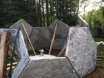
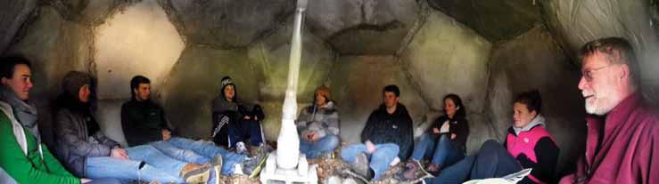
Figure 6. Nine people comfortably seated inside dome. Courtesy of Megan Strand-Jordan.
This system is a green technology which supports the concept of sustainable development. The system enables slender sections resulting in less cementitious materials in the members. Approximately 5% of global CO2 emissions are contributed by the production of cement and concrete (WBCSD 2008). According to many scientists worldwide, global warming is the most destructive problem humans now encounter. This system will result in benefits from cost savings, lower embodied energy and reduced CO2 emissions when compared to conventional approaches. Using the structural analysis laboratory at the University of Vermont, basic structural property tests such as bending and buckling resistance were conducted on test panels. The results from these tests will be used in a computer model to be constructed this fall and spring, for earthquake resistance analysis. the UVM campus, not only to attract the public’s attention, but also to get new UVM students involved in engineering projects. Finally, new structures using the carpet cement material are being designed, constructed, and tested for applicability in Vermont. The hope is to custom tailor designs to the regions of the world where these structures will be built. Disclaimer: The Dome was built with other safety systems in place that were not included in the article for brevity. Anyone who wishes to replicate this work should exercise caution. The Dome is patent pending. The hope is that, with a patent, the work will be protected and licensing of pre-engineered structural designs to non-profits and non-governmental organizations for use in relevant countries will be feasible.▪
What’s Next?
The most applicable places to build these structures would be in locations such as Haiti and other earthquake prone areas with easy access to cement. A pilot project is underway in which student volunteers from UVM will travel to Haiti with the Vermont Haiti Project and teach Haitian students how to build a structure using Dome materials and how to implement it in their communities. In addition, the team envisions a dome-like structure built right on
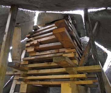
Figure 7. Inside view of interior cribbing/scaffolding. Courtesy of Megan Strand-Jordan. Matthew Brand is an undergraduate Environmental Engineering student at the University of Vermont studying the impacts of climate change on infrastructure. He can be reached at mwbrand@uvm.edu. Thomas Tailer has worked for the last eight years with the International Earth Science Olympiad and observed firsthand the impact of disasters such as earthquakes, typhoons, and fires on low income communities in developing nations. He can be reached at tbtailer@hotmail.com.
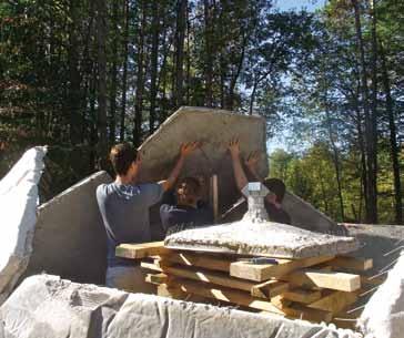
Figure 8. Second level panel supported and wired into place. Top panel with chimmney supported by cribbing in the foreground. Courtesy of Megan Strand-Jordan.

Cold-Formed Steel Provides the Strength Needed to Take Sustainable Building to a New Level
Green Terraces Present Design Challenges in a 10-Story Senior Housing Complex
By John Matsen, P.E.
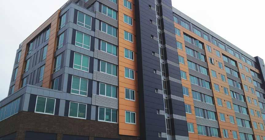
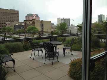
Figure 1. Th e terraces, totaling 12,000 square feet, are each support entirely by cold-formed steel.
Around 1900, the School Sisters of Notre Dame settled on a wooded hill in Milwaukee. According to the Milwaukee Journal Sentinel, the nuns built “a little pioneer home hidden under mighty trees.” More than a century later, greenery crowns another home built on the same hill: Convent Hill, a $9.9 million, 10-story senior residence with roof terraces fi lled with day lilies, spirea, phlox, shrubs and grass. Th e terraces are extensive. Th ey hold lightweight soil fi lled to a depth of three inches, ground cover plants and wild fl owers, and irrigation systems (Figure 1). Th e street level is retail, the second fl oor houses the offi ces for the facility, and the 3rd through 10th fl oors are senior residential apartments. Th e upper eight stories are cold-formed steel framed bearing walls and C-joists with Levelrock gypsum concrete fi ll on metal deck. Th e second story and below are hot-rolled steel framed with post-and-beam construction. However, the joists are cold-formed steel C-joists (Figure 2). Th e foundation walls, lower slab and footings are cast-in-place concrete. Th e main lateral resisting systems are cast-in-place reinforced concrete stairs and elevator cores. Th e cast-in-place concrete cores served to resist the lateral loads resulting from both wind load and seismic load. Th e concrete core was chosen over discrete bracing or cold-formed steel shear walls due to building height restrictions. Th e concrete core also aided in detailing and fi re rating of the shafts. Th e City of Milwaukee had the Convent Hill complex built in 1959. For the present redevelopment, the city wanted to take advantage of the latest environmentally friendly building designs. Th e structure, which features 12,000 square feet of green roofs, represents “a new level of sustainable and green technology,” states the Milwaukee Journal Sentinel. But how could the structure support the green roofs without a large and signifi cant use of structural steel? Matsen Ford Design Associates, Waukesha, Wisconsin, engineered the project’s cold-formed steel system, which comprises the majority of the structure’s support system.
Design Solution and Special Considerations
Cold-formed steel framing is the primary load-carrying structure for the upper residential stories. Cast-in-place concrete was used for the foundation walls, lower slab and shallow footings. Th e main lateral resisting system is cast-in-place reinforced concrete stairs and elevator cores. Th e combination of concrete and some structural steel with cold-formed steel supports 120 senior apartments and fi ve rooftop garden terraces. From the second fl oor upward, the structure features cold-formed steel joists that were prefabricated into panels to shorten construction times and eliminate on-site labor. Th ese joists leverage the strength and formability of coldformed steel with punched web holes to accommodate HVAC, mechanical, plumbing and sprinkler runs. Th e perimeter of the web holes had rolled edge stiff eners to add web strength and stiff ness over the entire span of the joist.
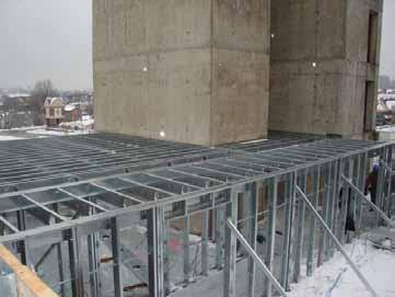
Figure 3. The design features pre-fabricated cold-formed steel joists, rim track and structural blocking.
The roof joists are cold-formed steel C-sections, 10-inch deep x 2-inch wide flange x 54 mil thickness, spaced at 24 inches on center for the 15-foot spans. Joist bridging was typically at 6 to 7 feet on center. Double C-sections 12-inch deep x 2-inch flange x 97 mil thickness where used for the longer 24-foot spans and 8-inch deep x 15/8-inch wide flanges x 43 mil thickness were used to span the corridors. The roof membrane is a screw fastened 1½-inch B deck with tapered insulation and ballasted EPDM roofing. The cold-formed steel joist roof structure at Convent Hill has the strength and stiffness to support five terraces each filled with a variety of greenery. The floor joists are cold-formed steel C-sections, 10-inch deep x 2-inch wide flanges x 54 mil thickness spaced at 16 inches on center. The joists were fastened into pre-punched tabs on ClarkDietrich Building System’s “Trade-ready” rim track (Figure 3), which facilitated maintaining the 16-inch center-to-center joist spacing. The rim track was also used in many locations to eliminate the need for load bearing headers. The rim track was fastened to the wall stud flange with either screws or welds. The floor framing supported a 0.6 C-deck with Levelrock gypsum concrete fill cover which served as the horizontal diaphragm to transfer lateral loads to the concrete cores. The wall framing, 6-inch deep C-sections with thicknesses from 97 to 43 mil having either 15/8-inch or 2-inch wide flanges, were used at interior locations; at the exterior wall locations the 6-inch deep
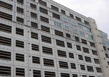
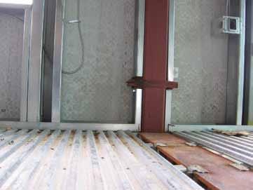
Figure 4. The 10-story Convent Hill senior housing complex features a new level of sustainable and green technology.
C-section thicknesses varied from 68 to 43 mils. The wall stud bridging was strap and blocking or channel with clip angle. To expedite the construction process, the walls were prefabricated on site. To ensure proper seating of the stud into the track, the stud panels were compressed to achieve tight seating of the wall stud. Typically, fabrication was done with welding because screw fastening of the thicker steel members proved too difficult. Development of a load path proved to be a design challenge. First, for vertical wall loads, the floor deck did not have sufficient web crippling strength; thus, deck crushing at the inter-story load transfer was a design concern. To resolve the inter-story load path, a steel-to-steel stud connection was used. However, this steel-to-steel connection resulted in a discontinuity for the diaphragm. The diaphragms had to be broken and additional perimeter fasteners used to ensure diaphragm continuity. Also, angles as drag struts were required at some locations to accomplish the diaphragm load path. Second, the marriage of the two systems, the concrete towers and the cold-formed steel framing, was necessary. Floor diaphragm forces were provided for inclusion in the design of the towers. The School Sisters of Notre Dame would be proud. The little hill in Milwaukee where they had built their home remains verdant and filled with life. The owner, too, is proud of the green contribution Convent Hill makes to Milwaukee’s Park East corridor (Figure 4).▪ John Matsen, P.E., is a Principal in the firm of Matsen Ford Design Associates. He also participates in multiple committees of the American Iron & Steel Institute’s Committee on Framing Standards. John may be contacted at john@matsenford.com.
Project Team
Structural Engineers: Norris & Associates Cold-Formed Steel EOR: Matsen Ford Design Associates Developer: Housing Authority of the City of Milwaukee Architect: Zimmerman Architectural Studios General Contractor: Gilbane Building Company Cold-Formed Framing Contractor: Worthington
Building Systems

Off-Site Assembly Reduces Schedule, Enhances Safety, and Cuts Costs
By Mark Warnecke, P.E.
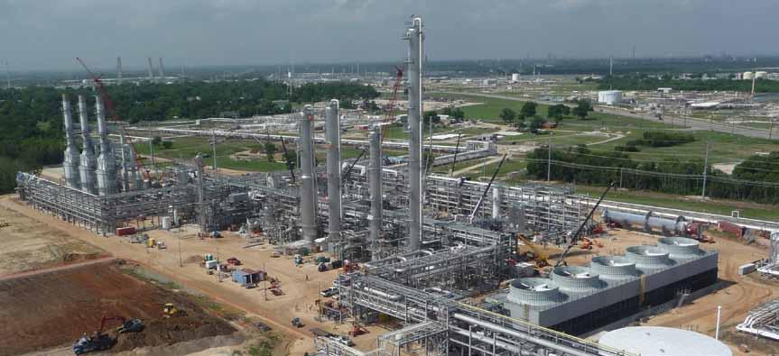
Figure 6: Completed module erection overview.
Domestic gas fi elds are rejuvenated using technologies such as hydraulic fracturing and horizontal drilling, which can substantially increase the supply of natural gas. Many formations also contain heavier hydrocarbons such as ethane, propane, butane, and gasoline. Th ese natural gas liquids (NGL) have a higher market value when separated from the natural gas stream and segregated into their individual components in a fractionation facility. Burns & McDonnell performed an Engineer, Procure, Construct contract for a new NGL Fractionation Plant for ONEOK Hydrocarbon, L.P. located in Mont Belvieu, TX. An aggressive schedule and rigorous safety plans encouraged off -site assembly of process unit components. Pipe racks were selected for modular construction, with completed modules shipped to the site and set directly from the truck. Assembly of modules in a controlled yard environment signifi cantly enhanced safety by allowing work closer to grade in a less congested area.
Module Summary
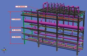
Module size selection is largely dependent upon the shipping method and overall crane lift weight. Although the project location is close to port facilities, the last 30 miles is an overland route. Modules transported overland must balance road/bridge height and weight restrictions, road width limitations, and associated permit processes against the largest assembly that can be safely lifted at the site. A detailed transportation study, coupled with an on-site crane lift study, is an eff ective tool to summarize the module size opportunities and limitations. In this case, the project team decided that two practical module outto-out dimensions were 16 x 61 feet and 20 x 61 feet. Module height was constrained by bridge clearance. Th e lowest beam of the pipe rack module rests upon the transport trailer, which is typically about three feet above the road. Module heights up to 15 feet from bottom of column overhanging the trailer to top of highest object are shippable. Module design for the NGL project was a three-tier system. “A” and “C” modules have two levels of piping and/or cable tray, while “B” modules have a single level of piping. “D” modules are relief valve access platforms, with the majority of the piping and valves installed in the shop. Th e Table on this page summarizes the NGL project modules. In addition to the customary design plans, elevations, and connection details, module design analysis and drawings include lifting requirements, transportation arrangements, overall weights, and center-of-gravity information.
Module summary.
Modules Number of Modules
Steel (tons)
Pipe Rack 100 (Modules 101 A/B/C to 108 A/B/C) 24 165 Pipe Rack 200 (Modules 201 A/B/C to 206 A/B/C/D) 19 120 Pipe Rack 300 (Modules 303 A/B/C to 309 A/B/C ) 21 160 Pipe Rack 400 (Modules 401 A/B/C to 403 A/B/C 10 85 & 402D) Pipe Rack 500 (Modules 501 A/B to 504 A/B) 8 65 Pipe Rack 1100 (Modules 1102 to 1104) 3 30 Pipe Rack 1200 (Modules 1201 to 1204) 4 35 Pipe Rack 1300 (Modules 1301 to 1303) 3 15
TOTALS 92 675
Connections
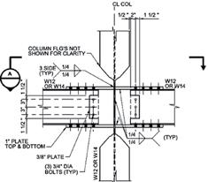
Modular construction’s eff ectiveness is related to the system of connections and whether they are made in the fabrication shop, module assembly shop, or fi eld. In general, bolted connections are lower-cost than welded connections, with all costs increasing in the fi eld. A mix of welded and bolted connections is typically selected for module assembly yard connections. Moment connections in the transverse and longitudinal directions are designed with full-penetration bevel welds at the transverse moment frames (Figure 1) to obtain the required strength without the need for bolted extended end plate connections. Bolts associated with such connections at the lowest beam would interfere with the fi eld assembly of module-to-module connections. Bolted connections also require larger shop fi reproofi ng blockouts, increasing fi reproofi ng’s total installed cost.
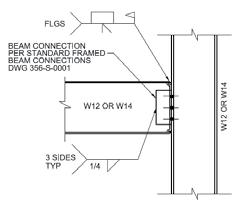
Figure 1. Transverse direction moment frame connection. Figure 2. Longitudinal direction weak-axis moment frame connection.
Figure 3. Typical module stack-up model.
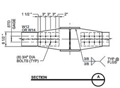
Longitudinal weak-axis moment connections with extended stiffener plates (Figure 2) at interior columns eliminate the requirement for temporary bracing to resist lifting and transportation loads, as well as the final pipe rack thermal loads. Pipe turnouts may be placed anywhere along the module, thus minimizing pipe runs to the process equipment. Careful attention to detailing and fabrication is required. Consideration should be given to oversizing the gap between extended stiffener plates to beam depth plus 1/8-inch, then installing shim plates to facilitate module shop fit-up and allow for fabrication tolerance. Simple shear connections at module exterior column lines create “clean” columns with no stiffener plates when setting the adjacent module; however, high axial loads in the stringers require clip angle connections. The solution is installing an angle beam seat in the web of the exterior column. The beam seat is sized for transportation and lifting loads and assembled at the module shop. Clip angles with through-bolted connections to the adjacent module are installed in the field prior to release from the crane. A “temporary” bent (green steel in Figure 3) is provided for module assembly, transport, and erection. Temporary connections are bolted for easy removal after module-to-module pipe welding is complete (Figure 4). Plates attached to the tops of all columns facilitate attachment of reusable lifting lugs. Bolts are replaced per the American institute of Steel construction’s (AISC) guidelines, but the lifting lugs may be reused many times with visual inspection of welds between lifts, reducing module costs. Steel piece mark identification issues had to be overcome. Application of protective coatings requires removal of shop-applied tags. Initially, a metal tie wire and paper tag system replaced the steel shop tag during protective coating. However, paper tags did not perform well during transport or handling at the module assembly shop. The solution was to apply a steel stamp in a location that would be visible after painting and shop fireproofing, such as the edge of splice plates or top of beams. This eliminated lost tag issues and provided piece orientation for the erection crews independent of the erection drawings. continued on next page
Fabrication & Assembly
Schedule flexibility is important to manage design of various pipe racks with input dependencies from multiple sources. The NGL project opted to purchase the steel directly from a fabricator and ship it to a protective coatings subcontractor, then on to the module assembly subcontractor’s yard. Protective coatings include a requirement for fireproofing meeting a UL-1709 two-hour rating for all steel within 30 feet of grade. The NGL project team selected a combination of intumescent fireproofing for the A modules and supporting columns, and an epoxy/urethane paint system. Primer and finish coats are the same for fireproofed and non-fireproofed steel, with only the tie-coat varying to simplify module yard and field touch-up.
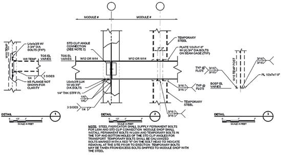
The protective coatings subcontractor’s yard is the staging point to align the steel fabrication, protective coating and module assembly schedules. Use of a lump-sum protective coatings subcontract for shop, module yard, and job site coating provides incentive to maximize shop work at the bid stage and create value for the client. Modular construction imposes lift and transportation forces from frame twist, bending and bearing on the transport trailer. Intumescent fireproofing was selected for several advantages, including: • Strength/durability during handling and erection, • Long-term reliability, • Maximizing shop-applied material, • Steel assembly estimated as 25% more efficient by the erection team, • Competitive total installed cost. Protective coatings are shop-applied to the maximum extent possible prior to shipping to the module assembly yard. Module assembly includes welding of bents at the column rows at grade, and assembly into modules via stringer beams bolted into the weak-axis moment connections at the interior beams and the beam seats at the exterior columns. Piping is installed and connections other than module-tomodule are patched prior to shipping to the job site.
Lifting, Transport and On-Site Erection
Modules are checked for loads created by lifting and transportation operations. Engineers must analyze and design transportation and lift plans for each module, applying factors to gravity loads in all three directions to model potential acceleration, rapid braking, and impact forces. One source for guidance is Cargo Securement Rules: USDOT Federal Motor Carrier Administration (2004). A rigging analysis is performed to calculate the assembled module center of gravity. Transport and lifting studies depend upon accurate pipe, valve and fireproofing weights and centers of gravity. Three-dimensional modeling tools provide the inputs. “Stick-built” columns, associated stringers, and vertical bracing that support the modules are erected along the entire length of a given pipe rack. Transverse bracing of the stick-built columns is omitted, since the moment frame is created as soon as the first module is bolted in place. Minor transverse lateral loads imposed by erection operations for the A modules are transferred to the foundation with the inherent moment resistance from the four-bolt base plate configuration. Modules are set from bottom to top. Incoming modules “rest” on the stringers below at the previous module end, and on a column splice plate atop the stick-built column or module post at the open end (Figure 5). Up to three modules per day were set at peak production, while targeting eight modules per week. Quality fabrication and maintaining assembly tolerances of plus or minus 1/8-inch any direction ensured flawless erection. Additional stick-built steel for access platforms, ladders, and pipe supports was field-erected using traditional methods to complete the pipe racks. See Figure 6 (page 40) for an overview of the plant with modular pipe racks erected.
Schedule, Cost, and Safety Benefits
Modular construction is favored by industry for its schedule advantages, inherently safer process, and reduced total installed cost. The Burns & McDonnell ONEOK project team was challenged to deliver an NGL Fractionation plant in an aggressive time frame while maintaining the highest standards of quality and safety, encouraging
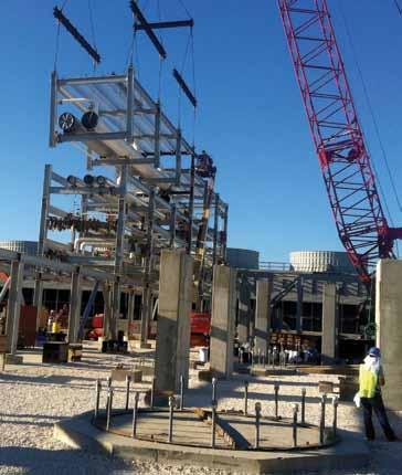
Figure 5. Erection of typical module.
as much off-site assembly of components as possible. Pipe rack modules with proven functional connection design features and protective coating systems, along with a highly effective subcontracting strategy, made it possible to deliver and set 92 modules, relocating approximately 2,100 linear feet of pipe rack assembly off-site. Careful module fabrication, assembly, and erection resulted in a flawless safety performance and shaved two months from the project duration.▪
Mark Warnecke, P.E. (mwarnecke@burnsmcd.com), is an Associate Structural Engineer in the Process & Industrial Group at Burns & McDonnell. He serves as the Lead Structural Engineer for the ONEOK Mont Belvieu program.
Project Team
Engineer of Record: Burns & McDonnell, Kansas City, MO Steel Fabricator: Markle Manufacturing Co. Inc.,
San Antonio, TX Protective Coatings Subcontractor: PK Industrial,
Augusta, KS and Houston, TX Protective Coatings Materials: International Paint Module Pipe Fabrication: Turner Industries Group, L.L.C,
Baton Rouge, LA Module Assembly: Turner Industries Group, L.L.C,
Port Allen, LA and Corpus Christi, TX Module Erection: Turner Industries Group, L.L.C,
Baton Rouge, LA


