8 minute read
POLY INTERNATIONAL

POLY INTERNATIONAL PLAZA,BEIJING
Evolution of an Icon


By Mark Sarkisian, P.E., S.E., LEED AP BD+C, Neville Mathias, P.E., S.E., LEED AP, and Rupa Garai, P.E., S.E., LEED AP BD+C
Overview
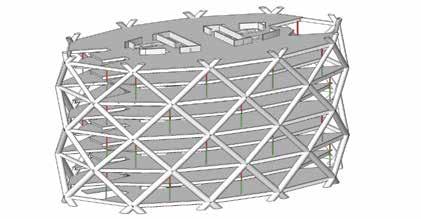
A chance to design an “iconic” building is not something one encounters every day. However, that is exactly what the designers at Skidmore, Owings and Merrill LLP (SOM) in their San Francisco offi ce got when they were challenged to come up with a design for the Poly International Plaza project in Beijing, China. It was a project that would further burnish the already stellar image of the client, the China Poly Group, renowned for its superior quality real estate holdings. e project was to consist of three offi ce towers totaling approximately 1.25 million square feet, one 530 feet tall – the “icon” – and two others, more conventional, about half as tall (Figure 1). e project site, prominently located beside a curved expressway in Dawangjing, a new and fast-growing business district about halfway between the center of Beijing and the international airport, provided the fi rst of many ingredients for a unique design. Shaped by their location, the curved boundaries of the site gave rise to the curved, relatively non-directional forms of the buildings. e structure and façade of the iconic tower, the focus of this article, were further inspired by origami Chinese paper lanterns, symbols of welcome traditionally hung over doorways and believed to attract good luck. e curved, faceted exterior form of the tower, with staggered nodes at every alternate level set on a four-story module and spaced approximately 60 feet apart horizontally, naturally suggested a “diagrid” exoskeleton structure, one capable of resisting lateral as well as gravity loads. Beijing is located in a region of relatively high seismicity (similar to Oregon and much of Washington), and the diagrid exoskeleton frame was combined with a central reinforced concrete core to yield a dual system that eff ectively and effi ciently resisted gravity and lateral loads. Constructed using concrete fi lled steel tubes (CFT) for most of its height, the diagrid frame made it possible, by virtue of the continuous helical load paths it aff orded (Figure 2), to transmit loads around corners and permit the creation of grand atriums. Unfi lled steel tubes were used at the upper levels where concrete fi ll was not required. e atriums – approximately 410 feet tall and located at the tower ends – let light into the building interior and provided views to the surrounding areas. ey also allowed for the introduction of structurally and visually exciting elements within them, like elevators, conference rooms, and spiral stairs (Figure 3).
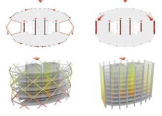
Structural steel floor framing, spanning approximately 36 feet programs (CSI’s SAP-2000) during the basic design phase. Nonbetween the core and external diagrid frame without interior columns, linear analysis programs (CSI’s PERFORM-3D) were used during and composite metal deck slabs constitute the floor framing system of the performance verification phase, discussed later in this article. A the tower. To avoid imposing significant gravity loads on the diagrid major concern of the project’s structural reviewers in China was the members between nodal levels, and to minimize bending moments in-plane adequacy of the diaphragms bounding the atriums, and the in them, intermediate floor levels were pulled back from the façade impact of cracking of these diaphragm slabs in a major earthquake on and hung from the nodal levels immediately above (Figure 4, page 36). the buckling stability of the diagrid structure. To address this concern, The three buildings on the site share a common three-story reinforced in-plane trusses were created in the diaphragms at these locations, concrete conventionally framed base- designed to provide equivalence to the ment, and the iconic tower rests on a slab diaphragm strength in case they pile-supported mat foundation. were rendered ineffective. Designers took advantage of the Diagrid structures tend to bulge in tower’s exterior diagrid system and plan as the diagonal modules comresulting facets, as well as of its press under gravity load, creating pulled-back and hung intermedi- circumferential and radial forces in ate floor levels, to develop a double the perimeter and radial floor framing skinned, glazed exterior wall system members, respectively, at nodal levels with automated operable vents at the and corresponding stresses in the diahorizontal creases. This arrangement phragm slabs. This bulging tends to created buffer zones in the spaces reach its maximum value at about between the double exterior walls one-third of the structure’s height and that act to modulate the extremes to decrease at lower levels because of of Beijing’s climate and the build- the restraint to spread of the strucing’s interior environment, reducing Figure 2. Lateral load paths. a) Diagrid frame (left); ture provided by the ground level the thermal loads on the building’s b) Typical frame (right). and sub-structure slabs. To ensure mechanical systems and saving energy. reliable structural performance, the This expedient served to boost the axial forces in the perimeter and radial tower’s sustainability performance, structural members were determined contributing to its goal of a LEED® neglecting the contribution of the Gold rating. diaphragm slabs, but the diaphragm slabs were nevertheless reinforced
Unique Structural to withstand induced stresses and minimize cracking. At levels where Challenges the diaphragm stresses were the The unique form and structural system of the Poly tower called for structural design checks and detailhighest, delayed concrete-placement zones were introduced to control slab cracking. ing not typically encountered in tall building design. The first challenge Structural was the modularization of the diagrid nodes. The perimeter floor framing Verification connecting the nodes, and the radial The structural verification process in framing connecting the nodes to the China requires buildings with noncore, typically had the same spans over prescriptive structural systems, such as the building height making it possi- the Poly tower, to undergo a rigorous ble to standardize the depths of these review by a panel of highly respected members and their intersections with seismic experts selected by the governthe diagrid diagonals. Horizontal and ment from academia and industry. vertical continuity plates, with holes to The experts not only evaluate the facilitate concreting of the CFT members, were introduced within the node Figure 3. Section showing atrium. conformance of such code-exceeding structures with the basic design and intersections to simplify and standardize their fabrication and erection performance requirements of the codes but also set enhanced per(Figure 5, page 36). Segments of the diagrid, each consisting of a node formance requirements for key components of such structures. The and diagonal arms, were fabricated in the shop, spliced with welds to process considers three levels of seismic hazard: frequent (50-year previously erected segments in the field, and then filled with concrete. return, peak ground acceleration [PGA] 0.07g), moderate (475-year One of the most significant differences between a conventional return, PGA 0.20g) and rare (2500-year return, PGA 0.40g) earthexterior frame and a diagrid frame is that the helical load paths in quake events. Along with various special analysis and design checks, a diagrid structure make it unnecessary for the floor diaphragms to non-linear time history analysis is required to verify conformance with extend all the way to the frame at the ends of the plan (Figure 2). Local the enhanced performance goals set by the seismic expert panel. In and global buckling studies of the diagrid structure, verifying frame the case of the Poly tower, this included no local or global buckling stability in the atrium areas, were performed using elastic analysis of diagrid members in the rare earthquake events, ensuring that nodes STRUCTURE magazine 35 November 2017
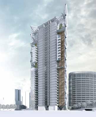
Figure 5. Typical diagrid node. with concrete, failure would occur due to buckling of the steel plate walls within the nodes. The wall thicknesses were set to avoid buckling of steel plates within the nodes in the accidental condition where concrete did not completely fill the nodes. This was generally found to not exceed two times the wall thickness of the diagrid members outside the nodes.

= Hanger = Fail-Safe Stub Column
= = HangeHanger r = = Fail-Safe Stub ColumnFail-Safe Stub Column Figure 4. Intermediate floor support. would not fail before the diagrid members, and ensuring gradual lateral strength loss of the structure progressing to eventual failure. Progressive collapse studies were required to ensure that, in the event of the catastrophic loss of a critically loaded diagrid member, enough redundancy and alternative load paths could be activated to ensure life safety. As a fail-safe precaution in the event of a hanger failure, stub columns were provided below the hangers with socketed slip connections at their bases. These are intended to engage and to transmit load to the framing of the level below if a hanger fails. To verify the procedures used for the design of the diagrid nodes, finite element analysis and scaled pseudo-static gravity plus lateral load testing of nodes with and without concrete fill was performed. Testing showed, as predicted by analysis, if the nodes were not filled
Conclusion
SOM was given a unique opportunity to design an iconic building at a prominent location in the new and fast-growing Dawangjing business district in Beijing. Opportunities presented by the site and cultural inspirations gave rise to a building which evolved to integrate form, function, structure, building systems, and sustainable design synergistically to create what is hoped is a memorable design.▪ Neville Mathias, P.E., S.E., LEED AP, is the Associate Director at Skidmore, Owings & Merrill LLP in San Francisco, CA. Mark Sarkisian, P.E., S.E., LEED AP BC+D, is a Partner at Skidmore, Owings & Merrill LLP in San Francisco, CA. Rupa Garai, P.E. S.E., LEED AP BC+D, is an Associate Director at Skidmore, Owings & Merrill LLP in San Francisco, CA.
ADVERTISEMENT–For Advertiser Information, visit www.STRUCTUREmag.org
STEEL BUILDING SYSTEMS MAKE THEIR GRAND ENTRANCE
Optimize your building design and construction
Reduce total-project costs. We are your nationwide resource for a broad range of custom-engineered structural steel building systems. We can help you determine the best solution for your application.
FREE
DOWNLOAD New white paper: Beyond the 5th Wall www.newmill.com/systems
