29 minute read
Structural Forensics
Many existing structures in North America experience ongoing moisture intrusion and resulting decay that significantly compromises the integrity of wood members. If left unmitigated, advanced decay in wood members supporting roofs, exterior walls, deck assemblies and floor systems can and does impair the capacity of these elements to support code-prescribed loads. The result is that portions of existing structures can become unfit for occupancy. The economic and environmental impacts are considerable as well; these include demolition and disposal of building materials before the end of their expected service life, expenditure of remediation labor and materials (every year, a significant percentage of new framing lumber goes toward fixing decayed portions of existing buildings) and loss of use costs. Substantial re-roofing and re-cladding projects can expose a veritable hidden jungle of decay. Detailed collection of field data on resulting section loss can provide valuable information as to the extent of structural damage and allow the engineer to re-construct a history of impairment for the structure. This article presents a method developed by the author for engineers to reasonably determine the occurrence of structural impairment of a decayed wood structure over its service life, and discusses its practical application in assisting with property insurance claims.
Residual Capacity in Wood Structures
The majority of wood framed buildings consist of thousands of elements connected together in such a way so as to create a superstructure. When engineers design wood structures with repetitive members (such as studs, joists and rafters), or members with slight variation in geometry and loading (such as beams and posts), these members are typically grouped according to function and load demand, and required member sizes are matched with available standard sawn or manufactured lumber dimensions. In some cases, member sizes are controlled by the attributes of interconnection; in other cases they may be oversized for architectural reasons; however, they should always be scheduled on drawings to ensure economy in construction. In this way, the elements that comprise existing wood structures have a range of residual capacity. If designed properly, members should have some level of “oversizing” – some have a little, some have a lot, but the majority fall somewhere in between. What is Decay Fungi? Decay fungi are primitive plants that feed on the sugars (cellulose) in wood. Fungi grow by lengthening and branching of tubular cells called hyphae, in a manner similar to the roots of plants (Highley). In nature wood decay fungi live on dead wood and in living trees, however, a small percentage are particularly well adapted for consuming wood that has been cut and worked into products used to build structures (Edmonds). The most destructive of these is brown-rot decay fungi, which preferentially attack softwoods. Since softwood species have predominantly been used in building construction, brown-rot decay fungi are the most common agents of decay in wood buildings (Carll and Highley). Just Add Water
Structural ForenSicS
investigating structures and their components
In order to grow, fungi require favorable temperatures, a supply of oxygen, adequate moisture and a suitable food supply (Carll and Highley). Constructed buildings offer a ubiqui- Decayed Wood Structures tous oxygen supply and temperatures that are comfortable to humans, which are also ideal Reconstructing a for the growth of decay fungi (Morris). Wood moisture content is therefore the most imporHistory of Impairment tant factor in determining decay. Decay fungi require free water, so wood must be above the By Lee Dunham, P.E., S.E. fiber saturation point (about 28% MC on a dry weight basis) but below the waterlogged condition to decay (Edmonds). Even though modern building enclosure design and construction have come a long way in the last 20 years, many existing buildings lack the proper means of protection against water intrusion. When breaches in waterproofing systems result in water intrusion, moisture contents in framing elements can elevate from those at equilibrium moisture content (equivalent to 8-10% in most parts of the country) to those conducive to growth of decay fungi in a relatively short amount of time. Some components of exterior wall assemblies, such as batt insulation, can trap and hold water against framing members. Lee Dunham, P.E., S.E., is a structural engineer specializing in the investigation and repair of existing structures. Originally hailing from Fredericton New Brunswick, Canada, Lee is a Senior Associate with OAC Services, Inc., an architectural, engineering and construction management firm in Seattle, WA. He may be reached at High-Early Strength Loss ldunham@oacsvcs.com. Engineers that design with concrete are familiar with the concept of “high-early strength gain”. With decay, engineers need to be familiar with the concept of “high-early strength loss”. Decay initially affects toughness, or the ability of the wood to withstand impacts. This is generally followed by reductions in strength values related to static bending (Wilcox). Eventually, all strength proper- The online version of this ties are seriously reduced. Strength losses during article contains detailed the early stages of decay can be considerable. references. Please visit continued on next page www.STRUCTUREmag.org.
Just Point, Shoot and Measure!
1. 2.

Remote Detection of Vibrations on Large and Distant Structures
Non-contact, optical vibration meas urement on civil structures for health monitoring and FE model validation ■ Long stand-off distance ■ True 0 Hz capabilities with mHz re so lution for low frequency response and displacement measurements ■ Small laser spot – precise target ing, e.g. on cable-stayed bridges ■ Easy targeting with integrated video camera ■ Easy set-up in minutes – no cabling or measurement point preparation ■ Sub-μm resolution – for reliable results
Polytec GmbH 76337 Waldbronn · Germany www.polytec.com
3. 4.
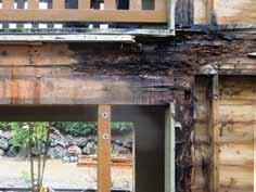
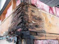
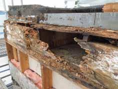
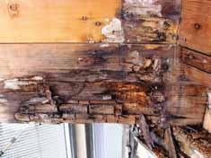
“The Hidden Menace”. Advanced brown rot decay in wood framing members in Pacific Northwest buildings; 1 – despite their appearance as rim joists, these are actually double 2x12 beams bearing at a corner post in a multi-family residential building; 2 – impaired elevated walkway beam, rim and studs; 3 – glulam header with advanced decay and structural impairment at right side bearing; 4 – double 2x10 rim with full section loss below a low-slope roof in a single family residence.
By the time weight losses in wood members resulting from decay have reached 10%, loss of most mechanical properties may be expected to exceed 50% (Highley). When wood is in the advanced stages of decay, it essentially has lost all strength. Decay Progression Although the precise growth rate of brown-rot decay in wood framed buildings is generally not determinable to a high degree of scientific certainty, research in the field of wood science has provided sufficient knowledge to allow the shape of the decay ‘curve’ to be bracketed with an upper bound and a lower bound. In this way, decomposition envelopes can be reliably determined for wood structures, as the data available from laboratory and field studies are based on the same wood used in buildings, the same decay fungi (brown-rot) and similar moisture and temperature environments.
Structural Impairment
The Usual Suspects The most common locations for water intrusion at the exterior walls of buildings are at windows, doors, corners and other transitions in the building enclosure system. Certain types of cladding systems have a poor track record of managing water. Water that has leaked into a building can wet vertical and horizontal wood framing elements. Where water collects at and saturates horizontal wood surfaces, the saturation spreads horizontally. As goes the water, so goes the decay. A typical location of advanced decay in framed walls is at the base of studs, plates and rim joists. The list of “usual suspects” at post and beam structures such as decks includes beam ends and the tops and bottoms of posts. Deterioration can occur at locations where bending stresses are the highest, such as cantilever points for beams at balconies. However, practically speaking, the most common mechanical properties affected are compression perpendicular and parallel to the grain, as water gets funneled to and accumulates at bearing points which often coincide with architectural corners or transitions. Dowel-type connections between wood elements such as nails, screws and bolts are also commonly affected. Low-slope roofing systems, if not constructed properly, can also be ripe for decay resulting from water intrusion and/ or condensation of internal vapor caused by the lack of proper ventilation.
Diminished Load Carrying Capacity When a structural member is damaged or weakened through diminishment of some
Figure 1: Impairment range example (illustrative only).
material aspect, it is called impairment. When load carrying capacity is diminished by decay to the point that the member can no longer support the associated code load demand, the member is impaired in its capacity. In order to determine if the member is impaired, the engineer is required to calculate the capacity of the remaining “good wood” and compare this to the calculated load demand on a case by case basis. Impairment thresholds are defined by the engineer based on his or her engineering judgment, and in a manner that is consistent with provisions set forth in governing building codes.
Time Distribution of Impairment
Time distribution of the occurrence of impairment to wood framing elements in a building over its service life can be reliably modeled using a combination of applied structural engineering, wood science, and basic statistics. Step 1 – Investigation and Research Typically, wood goes into a building sound, and (hopefully) dry. When deterioration of existing wood framing elements is observed some time after construction, the question is – how did it get from point A (dry, sound) to point B (decayed, impaired)? Typically, for buildings constructed in the last 30 years, construction dates can be gleaned from building department records. Sometimes, maintenance records kept by building owners can provide an understanding of water intrusion history and timing of any past repairs. Engineering investigations can include studying the arrangement and condition of the building enclosure components that permitted long term water entry. In some cases, service life of failed waterproofing can be estimated based on experience and industry knowledge. In terms of rate of decomposition of wood in buildings due to decay, an engineer can provide reliable extrapolations of the most aggressive rate of decay and the least aggressive rate of decay, and use these in combination with estimated earliest and latest decay start times (based on water intrusion history and/ or specific envelope failures) to reasonably estimate a decomposition envelope applicable to the building in question. Step 2 – Estimating Time Ranges for Impairment For each member affected by decay, measure the section loss at the time of observation. As described in Figure 1, next calculate the section loss that corresponds to the point at which the member’s load carrying capacity becomes impaired. Then plot the impaired section loss relative to the observed loss on a graph. Superimposing this on the estimated decay envelope, determine the points in time when the impairment threshold intersects the upper and lower bounds of the decomposition envelope. This gives a range of years – the impairment range – for each member. Repeating this exercise for other affected members in the structure provides a group of impairment ranges. If the sample is representative of the different types of structural damage documented at the building, so too is the set of impairment ranges.
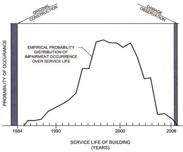
Step 3 – Empirical Probability Distribution Step 2 results in a set of ranges that represent likely time frames for various members to have entered a state of impairment. Plotting all the impairment ranges on a graph provides a relative frequency distribution of impairment over the service life of the building. With a straightforward mathematical calculation, this frequency distribution can be converted to an empirical probability distribution. These plots can then be used to estimate the percentage of structural impairment in any period of interest throughout the service life of the building. continued on next page
Cross-Hole Analyzer
Your best CSL choice.
sales@pile.com +1 216-831-6131 Cross hole sonic logging of drilled shafts per ASTM D6760.
CHA-W software
Optional probe deployment system.
Figure 2 is the result of analyses performed on a series of wood framed buildings in Seattle, based on the methodology summarized in this article. The author collaborated with Professor Robert Edmonds, Emeritus Professor and wood decay expert at the University of Washington, to model the decay envelope applicable to these buildings. The buildings were constructed in the mid-1980s; observation of decay damage was documented during a 2008 reclad. Building enclosure conditions permitting long-term water intrusion (such as failed sealant joints) were documented. Known areas of past framing repairs were used as a check on the decomposition envelope. The total area under the curve represents 100% of the impaired framing members. When long term decay meets a range of residual capacity, there is a smaller percentage of members entering a state of impairment in the early and later years, and a larger percentage in the middle years.
Property Insurance Disputes
Some property insurance policies include an additional coverage that has been interpreted by courts to cover certain types of structural damage. In some cases, this includes structural impairment caused by decay. Substantial structural impairment caused by decay can result in considerable financial losses that create a dispute between the insured building owner and/or two or more insurance companies that insured the building during different periods of the building’s service life. In these cases, structural engineers are often retained to assess the deterioration of wood framed structures caused by decay, and present opinions on the extent and timing of impairment. Opinions
Figure 2: Empirical probability distribution of impairment over service life.
are not required to be based on perfect scientific certainly, but rather, on the “more probable than not” civil case law standard. The role of the forensic structural engineer in such cases begins with a reasonable investigation of the damaged building. This involves either representative sampling by means of destructive testing, or in some cases, a census of damage taken when cladding assemblies are removed in whole or in part. The engineer then carries out an analysis using the data obtained to form his or her opinions. There are two “gate-keeping” standards used by courts to decide whether or not scientific evidence is admissible. Both are aimed at identifying scientific evidence that is reliable. One is the “Daubert” standard used by Federal Court, and the other is the older “Frye” standard employed by some state courts. Both are similar in that they aim to weed out “junk science”. The methodology presented in this article has passed both the Daubert and Frye standards in recent insurance disputes involving buildings in the Seattle area. Even though the methodology summarized here pertains to wood structures, the Author suggests that a similar approach may be applied to steel and reinforced concrete structures.

STRUCTURAL ENGINEER
Conclusions
10 years Minimum of Structural Design experience in buildings and/or transportation structures.
Apply at: Structural Engineering Associates, Inc. 3838 NW Loop 410 San Antonio, TX 78229
or email resume to: jpuente@seatx.com
Long term water intrusion can wreak havoc on structures. Structural engineers that consult on existing buildings and other structures should familiarize themselves with the types of conditions that can result in water intrusion, and elements of the superstructure most prone to damage, such that owners receive diligent advice. In working with contractors and architects, structural engineers should take a proactive interest in waterproofing. Analyses that allow damaged buildings to tell their own story can be powerful tools when applied in a reasonable and reliable way. When the standard of proof is “more probable than not”, and unbiased engineering methodologies are applied to representative data consistently, reasonable and reliable impairment ranges can be estimated. When required to resolve disputes involving decayed wood structures, engineers should consider using the applied science approach set forth in this article to determine the occurrence of structural impairment of a building or other structure over its service life.▪



Historic Arch Bridge Historic Arch Bridge Reborn with Progressive Design Reborn with Progressive Design
By Chad Clancy, P.E. and Mike House, P.E.

The Burnt House Road Bridge, a historic bridge set in the countryside of rural central Pennsylvania, was in need of an update – and it needed it quickly. After being closed to traffic in 2009 following an underwater inspection that revealed undermining of the foundations, the Pennsylvania Department of Transportation (PennDOT) needed a solution that would quickly bring the bridge back into operation for the nearly 2,100 cars that cross the bridge on a daily basis. Constructed in 1912, the bridge carries Burnt House Road over the Yellow Breeches Creek in Dickinson Township – about 30 miles outside of Harrisburg, PA. At nearly 100 years old, the single-lane bridge already had a posted load limit of only three tons, which was not conducive for normal traffic – let alone nearby quarry traffic. After the 2009 closure, Dickinson Township, which owns Burnt House Road, and PennDOT, the bridge’s owner, embarked on an evaluation process to determine if the original bridge could be rehabilitated or if it would need to be replaced altogether. Bridge engineering firm Modjeski and Masters was engaged for preliminary and final design, and faced the challenge of balancing the community’s preference to preserve the appearance of the original “humpback” bridge with modern day traffic demands.
Context Sensitive Design Calms Community Concerns
Because of the community’s attachment to the visual aesthetic of the original bridge, context sensitive solutions were an important design consideration. These solutions needed to not only preserve the look of the original bridge, but also to improve bridge functionality and safety for pedestrian and vehicular traffic. The replacement bridge design is composed of a wider bridge that now accommodates two lanes of vehicle traffic with a sidewalk that facilitates safer pedestrian traffic. A new sidewalk was incorporated on the same side of the road as nearby Stuart Park – an added safety feature for park visitors and Yellow Breeches Creek fishermen alike. The new, three-barrel arch structure chosen for the replacement bridge serves a dual purpose. First, the center barrel is raised relative to the outer barrels, which maintains the humped profile that was important to the community. Second, the large opening of the center barrel improves hydraulic functionality by better accommodating stream flow and preventing an increase in backwater, which in turn reduces the risks of flooding nearby properties. Finally, the new bridge’s stone facade was created to replicate the look of regional limestone used in the construction of nearby historic structures. Arch headwalls were fabricated using stacked stone pattern formliners to give the appearance of stone. The concrete was then stained to mimic the regional grey limestone.
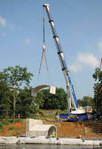
Other improvements were incorporated into the designs to streamline construction, improve traffic flow and decrease future maintenance. Because Burnt House Road is a primary travel route through Cumberland County, and the bridge was already closed to traffic, getting a new bridge back into operation as quickly as possible was important to PennDOT and Dickinson Township officials. Accelerated construction alternatives were evaluated, and the final designs incorporated 30-ft. pre-cast CON/SPAN arch units to streamline construction time. The Yellow Breeches Creek is deemed a high-quality, stocked and naturally producing trout stream. The Pennsylvania Fish and Boat Commission regulates in-stream construction to prevent disruptions to trout reproduction. As such, in-stream construction activities between March 1 – June 15, and October 1 – December 31 are prohibited. Because the available window for construction time is limited by these

regulations, the use of prefabricated arch units drastically reduced the amount of time construction teams needed in-stream access.
Asphalt Deck Streamlines Future Maintenance
Another benefit to the use of CON/SPAN units was the ability to incorporate an asphalt deck versus a reinforced concrete deck. Bridge redecking typically occurs every twenty to thirty years, and can be a lengthy process with a substantial price tag and can often require substantial bridge closures. Repaving saves future costs associated with ongoing bridge maintenance, reduces traveler headaches and improves bridge longevity. Further, PennDOT’s ultimate goal is to transfer ownership of the new bridge to Dickinson Township, so future maintenance and its impact on the local taxpayer was an important consideration.
Improved Alignment and Traffic Flow
To facilitate better traffic flow across the bridge, the project also involved modifications to the horizontal alignment of Burnt House Road. Prior to the bridge replacement project, the road had a distinct “kink” immediately prior to the bridge on the south side. The design team incorporated a new alignment that eliminated the kink, enabling traffic to flow more freely across the bridge. One of the major challenges the design team faced when creating a new alignment was working within the given right of way. Because of historic structures nearby, including a stone farmhouse, ruins from a stone barn and nearby wetlands – all of which were important historic and aesthetic components of the bridge setting – the new alignment would need to be created in a way that avoided any impacts on these elements. Gilbert Cornwell, former Dickinson Township resident of more than fourteen years, believes he speaks for local residents when he says he is “very pleased” with the new bridge. “I have heard people talking who wanted the bridge to be shut down completely, and now they say it’s a very nice bridge. We are very pleased with the new bridge.” Township manager, Laura Portillo commented that “the beauty of the bridge speaks volumes” and added that many residents comment on how great it looks; that it kept the feel of the old bridge. The Burnt House Road Bridge replacement project served a critical need in Dickinson Township, PA. Closed to traffic because of its current condition, the township needed a new bridge that maintained the same aesthetic qualities – quickly. Modjeski and Masters incorporated design features such as prefabricated CON/SPAN arches to streamline construction, while at the same time focusing on context sensitive design solutions to maintain a similar bridge profile and appearance
Courtesy of Cumberlink.com.
to best compliment its natural setting. The new Burnt House Road Bridge will ultimately save taxpayer dollars by reducing the amount of future maintenance, while helping to prevent future lengthy bridge closures due to redecking.▪ Chad Clancy, P.E., is a Structural Project Manager at Modjeski and Masters with 20 years of experience as a bridge designer. He can be reached at CMClancy@modjeski.com. Mike House, P.E., is a Lead Highway Engineer at Modjeski and Masters with 15 years experience in transportation design and construction and can be reached at MDHouse@modjeski.com.
forbridges Planes, Trains,
buT noT auTomobiles
By David A. Burrows, P.E., LEED AP BD+C
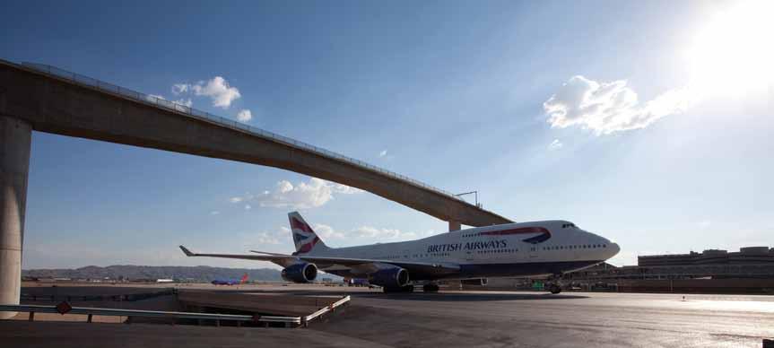
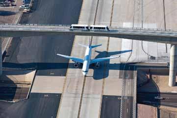
British Airways 747 crossing beneath the Taxiway “R” bridge, June, 2012. Courtesy of City of Phoenix Aviation Department.
A US Airways jet passes beneath the Taxiway R crossing with the PHX Sky Train overhead. Courtesy of City of Phoenix Aviation Department.
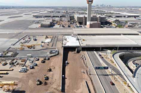
As described in the August edition of STRUCTURE® magazine, Phoenix Sky Harbor International Airport opened the first stage of their automated transit system, PHX Sky Train™, on April 8, 2013. Thousands of passengers have already boarded the Sky Train and experienced the comfortable five minute ride from the 44th Street Station through the East Economy Lot Station, over Taxiway “R” (more than 100 feet above Sky Harbor Blvd.), ending at Terminal 4. The next phase, known as Stage 1A, is currently under construction and continues Sky Train’s route from Terminal 4 to Terminal 3. Scheduled to be open in early 2015, Stage 1A, similar to the Stage 1 construction, faces the task of crossing an active taxiway. Unlike the first Stage’s crossing above Taxiway “R”, the current phase of construction crosses beneath Taxiways “S” and “T”. Both Stages’ taxiway crossings presented several design and construction challenges.
The World’s First
On Oct. 10, 2010, a celebration to mark the re-opening of Taxiway “R” was held by the City of Phoenix with members of the City’s Aviation Department, designers, contractors and media watching as the first two planes taxied under the new bridge. Nowhere in the world had this been done before, a bridge carrying trains over an active taxiway; even more remarkable, a taxiway that handles planes as large as Boeing 747’s. Delivered a week ahead of schedule and approximately 35 percent below the initial budget, there was reason to celebrate. To make this crossing a reality, creative problem solving by both design and construction teams was necessary.
Design Constraints
An area 340 feet in length and 75 feet in height above Taxiway R was needed to provide the clearance required for Group V Aircraft (Boeing 747’s). Additionally, to stay below the Part 77 surface established by the Federal Aviation Administration for safe aircraft operations, the height of the bridge was limited. Thus, a narrow vertical band of approximately 40 feet remained within which the bridge could be built. Taking into account the vertical curve and bridge barrier, the vertical band reduced further to just over 30 feet. In addition to the challenging geometry was the schedule constraint for constructing the bridge. Because the construction required the taxiway to be closed, a limited shutdown period of six months was possible due to airport operations. The timing of the shutdown was an additional factor to be managed. Due to seasonal traffic volumes, the closure had to occur between Spring Break and Thanksgiving. If this window was missed, it would delay construction of the bridge, which would delay the entire project. Obviously, it was critical to choose the correct structure and get the design and construction right the first time. Eight alternatives were evaluated and ranked based on impacts to the taxiway, long-term maintenance, cost, aesthetics and special considerations specific to each structure type. Evident from a drive on metro-Phoenix’s freeway system, concrete box girders are a popular choice, which require little maintenance, only routine inspection and, in many cases, a lower life-cycle cost. Aesthetically, the box girder was the most streamlined and least obtrusive choice, fitting nicely with surrounding concrete structures and adjacent guideway. Thus, a cast-in-place box girder bridge was chosen. Concern arose regarding the cost of falsework supporting a superstructure 90 feet above grade during construction. In order to minimize disruption to the taxiway, end spans (which did not require a taxiway
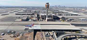
A Southwest Airlines 737 crosses over the newly completed Taxiway “S” bridge. Courtesy of Visions in Photography.
shutdown) would be constructed fi rst. To reduce falsework cost, the CM-at-risk contractor recommended that the designers determine a way to re-use the end spans’ falsework for main span construction. Design based on this concept was completed in July, 2009. Th e contract to build the bridge was awarded in September, 2009. With the demand for construction impacted by the recession, the bridge contractor found an abundant supply of falsework material, and proposed supporting all three spans simultaneously until post-tensioning was complete. Th erefore, the elements added to accommodate the reuse of falsework were no longer necessary. A redesign of the bridge, which eliminated supplemental post-tensioning and closure pours, was completed in three weeks; a quick turnaround to keep construction on schedule.
Construction Phase Challenges
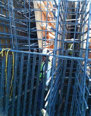
Tight construction clearances were common and unavoidable during construction. While the taxiway remained A construction worker within the tight clearances of Taxiway “R”. Courtesy of Hensel Phelps Construction Co. open, construction began with pier foundations. Due to the close proximity of traffi c on Sky Harbor Blvd and a bridge over a nearby local street, the foundation for the eastern main pier proved particularly diffi cult to construct. Th is was overcome by installing the drilled shafts from existing grade, rather than excavating fi rst and drilling from the bottom of footing grade as conventionally done. A trench fi lled with slurry was placed to form the perimeter of the pile cap to allow for the 10-foot deep cap excavation without impacting the adjacent area. Another challenge encountered while building the superstructure was in forming the deepest sections of the webs near the main piers. Because the webs tapered Design/Build in thickness, working space for forming Earth Retention and stripping became extremely limited (as shown in upper right graphic). Once Foundation Support the fl oor and webs of the girders for the end spans were constructed, the taxiway Slope Stabilization was shut down in April 2010 to begin the Ground Improvement construction of the main span. Th e deck was poured continuously over all three Dewatering spans, and post-tensioning of the bridge occurred in early September 2010. Arguably the biggest challenge to construction was the tight and unmovable 800-562-8460 WWW.DBMCONTRACTORS.COM Donald B. Murphy Contractors, Inc.
schedule. It required tremendous planning efforts that included several hour-by-hour internal schedules for weekend and critical activities, such as falsework lowering. Executing necessary restrictions on Sky Harbor Blvd. and surrounding roadways, required countless emails and hours of phone calls to communicate between contractors, airport operations, airlines, vendors, and the travelling public. Crews worked through most holidays and weekends, and out of 307 available shifts, the contractor worked 272 shifts or nearly 90 percent of the total time available.
Taxiways “S” & “T” Going Below the Surface
In contrast to the highly visible crossing above Taxiway “R”, the crossings below Taxiways “S” and “T” will be invisible to all but the passengers on the Sky Train. Why cross above one taxiway only to then cross beneath another two? Extensive coordination and planning determined that an elevated Taxiway “R” crossing provided the optimal alignment into the Terminal 4 Station. Additionally, the amount of utility relocation required by constructing beneath the taxiway made that option infeasible. Utility relocations, while a concern, weren’t as problematic at Taxiways “S” and “T”. However, because the two taxiways, at 210 feet wide, are only separated by 50 feet; placing a pier between them would violate clear zone requirements. The resulting span length would be 600 feet, a superstructure capable of that span, apart from being uneconomical would have been impossible to fit in the narrow vertical band described for the Taxiway “R” crossing. Phoenix Sky Harbor International Airport has been the city’s airport since 1935, so the existence of underground utilities that are unaccounted for, abandoned and forgotten, or located incorrectly on utility maps is not
Software and ConSulting FLOOR VIBRATIONS
FLOORVIBE v2.10
• Software to Analyze Floors for Annoying Vibrations • New release • Demo version at www.FloorVibe.com • Calculations follow AISC Design Guide 11 Procedures • Analyze for Walking and Rhythmic Activities • Check floors supporting sensitive equipment • Graphic displays of output • Data bases included CONSULTING SERVICES
• Expert consulting available for new construction and problem floors. Structural Engineers, Inc.
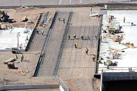
Work on the Taxiway “S” anchor slab. Courtesy of Visions in Photography.
surprising. While understandable, the potential consequences of unknown utility lines directly conflicting with new construction can be disastrous. Instances of unforeseeable conflicts arose in Stage 1 construction, which cost several weeks of construction time to resolve. With only a six month construction duration for each undercrossing, a delay due to a hidden conflict could disrupt the schedule for the entire project and, more importantly, the operations of the airport which requires that all taxiways be open from Thanksgiving to New Year’s day.
Design Innovation
To mitigate the risk of utility conflicts, the designers took an innovative approach to the undercrossing design. The design contemplated adding a new span on the south end of each taxiway. Typically, construction for a new bridge abutment would require a large amount of excavation and thus greatly increase the chance of uncovering unknown utilities.
Therefore, the designers developed an abutment wall consisting of 54-inch diameter drilled shafts approximately 50 feet long at 10-foot spacing, restrained at the top by an anchor slab and with the gap between each shaft filled with a reinforced shotcrete wall. This allowed the new abutment to be built with no excavation behind the drilled shafts, except for the shallow depth required for the anchor slab shear keys.
Another innovative idea that mitigated schedule risk was to use the existing taxiway bridge abutment as a support for the new span. The initial design proposed building a new pier adjacent to, but outside the footprint of the existing abutment, with a reinforced concrete slab to span the short gap between the two supports. During final design, this concept was eliminated after determining that loading from the new span would cause less stress than the fill behind the existing abutment. With a relatively small amount of concrete added to the existing abutment to accommodate the new span, the duration of construction was shortened. As required by Airport Operations, only one taxiway could be shutdown at a time. Construction began with Taxiway “S” on May 22, 2012 and was completed five days ahead of schedule on November 14, 2012. The new superstructures were built using the “soffit fill” technique, where the superstructure was built directly on compacted fill and, after post-tensioning, the fill is excavated to reveal the soffit of the bridge. This technique also contributed to shorter construction durations. Taxiway “T” was shut down on January 7, 2013 and was re-opened with its new span on June 11, 2013, three weeks ahead of schedule. The cost for both undercrossings came in approximately ten percent below the initial budget.▪
David A. Burrows, P.E., LEED AP BD+C, is a senior structural engineer at Gannett Fleming, Phoenix, Arizona. He was the lead engineer for the design of the Taxiway R crossing. David can be reached at dburrows@gfnet.com.


