39 minute read
Technology
In late 2013, Iowa’s Buchanan County engineers teamed with academia and industry to launch the V65 Jesup South Bridge Demonstration Project with the goal of illustrating the advantages of the eSPAN140 short span steel bridge design tool to accelerate steel bridge design and construction. At the heart of the design tool, developed by the Short Span Steel Bridge Alliance’s (SSSBA), the steel industry and Steel Market Development Institute (SMDI), is the use of standard steel beams and other elements that are readily available from the steel industry. The success of the tool strongly depends on the ability of steel fabricators to turn around the conceptual designs produced by the tool with minimal work. U.S. Bridge teamed with other industry partners to complete the demonstration project and assess the value of the tool to speed the delivery of bridge elements to the jobsite.
Bridge Basics
The old Jesup South Bridge is located on one of the busiest roads in Buchanan County. Originally built in 1947, the deteriorating structure had a sufficiency rating of 49, making it a prime candidate for replacement. The bridge was narrow and not built for the loads required to support today’s traffic. County engineers sought to replace the existing 22-foot-wide bridge with a modern 40-foot-wide bridge using galvanized steel rolled beams and galvanized rebar. Around the same time, Buchanan County’s County Engineer Brian P. Keierleber, P.E., heard about the development of the eSPAN140 tool and the interest by the researchers at West Virginia University, the University of Wyoming and the SSSBA in documenting the benefits of the tool. Keierleber volunteered the Jesup South Bridge as a candidate for the SSSBA’s proposed demonstration project because the demonstration project presented a unique opportunity to see how the eSPAN140 tool could streamline the steel bridge design and construction process and open the door to alternative bridge replacement options. While the project was mostly driven by Buchanan County, SSSBA sought volunteers from the bridge design and construction community to facilitate the project (see Jesup South Bridge Demonstration Project Team sidebar). As an SSSBA member, U.S. Bridge knew about the development of the eSPAN140 tool. The demonstration project provided a perfect opportunity to translate the eSPAN140 data to design and fabrication in a practical setting. All the project participants visited the site to gain a full picture of the project and discuss expectations. For U.S. Bridge, the biggest concern at the time was to clarify responsibilities for the volunteer team, since the process would be a little different than a conventional project delivery.
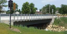
New Jesup South Bridge designed with standardized steel beams with eSPAN140 tool.
Technology
information and updates on the impact of technology on structural engineering
Concept to Construction
In September 2013, Keierleber logged into the eSPAN140 site to design the new Jesup County Bridge. He input bridge length, width and number of lanes. He wanted a bridge with a 63-foot span and two striped traffic lanes, supported by five standard girders. The eSPAN140 tool is coded to use the AASHTO LRFD bridge code and corresponding HL-93 Vehicular Loading design codes. Within minutes, he received a customized steel bridge design as a PDF Fabricator’s Inside file that echoed his inputs and organized Perspective on Standardized the information in a commonly depicted Steel Bridge Design format (a format normally found in a set of contract documents). The eSPAN140 eSPAN140 plans indicated composite beam sections from a W40x149 (the deepest/lightest beam) Facilitates Speedy to a W24x192 (the shallowest/heaviest beam) for Concept-to-Completion a bay spacing of 10 feet 6 inches. These results, called a “Steel Bridge Solutions” By Dennis Gonano, P.E. file from eSPAN140, also included typical bridge cross-sections and roadway widths, travel lanes and shoulders, and more, as well as the design and fabrication details for standardized rolled beams with slab thickness, girder spacing, bear- Dennis Gonano, P.E., is the ing elevations and stiffener positions shown. It’s Director of Engineering at U.S. worth noting here that eSPAN140 does leave Bridge. He can be reached at off at a certain point. For instance, if the bridge dgonano@usbridge.com. engineer doesn’t select the shallowest depth or lightest weight options that eSPAN140 offers for the optimal spacing, the engineer or fabricator will need to complete a final analysis and some design tasks to calculate accurate deflection values (for camber) and any updates to the shear stud spacing. Buchanan County’s County Engineer especially liked the user-friendly appeal of the eSPAN140 tool, which facilitated price comparisons of different bridge concepts to find the most economical solution. With plans in hand for the new Jesup South Bridge, Keierleber prepared contract drawings and coordinated the design with U.S. Bridge, who would model, detail and fabricate the short span steel bridge elements. continued on next page
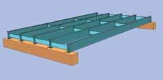
U.S. Bridge modeled, detailed and fabricated the short span steel bridge elements based on initial design details from eSPAN140.
The County’s design plans reiterated the use of composite beam/deck construction, jointless integral abutment details and steel channel members as diaphragms – all consistent with Iowa DOT standards and the details given by eSPAN140. For the bridge railing, the County proposed a new crash tested steel post and w-beam rail called the MGS Bridge Rail System. The County’s selected framing layout consisted of five lines of W36x135 spaced at 8 feet 8½ inches and a slab overhang of 2 feet 7 inches. The diaphragm channels were MC18x 42.7 and were located at each bearing and at approximately one-third points along the span. Once the designer’s criteria was fully specified, eSPAN140 provided the level of detail that U.S. Bridge needed to move immediately to the next stage – and it was pretty easy to do. The steel bridge solution details outlined in the eSPAN140 results file provided enough information to drive the finer detailing requirements and fabrication processes. In addition to the erection plans and shop drawings, the U.S. Bridge team added some construction plans including a stay-in-place (SIP) formwork layout and railing installation plan, and supplemented the construction documents with some Iowa Department of Transportation standards because they were referenced by the county engineer.
High-Gear Fabrication
Plans for erecting the steel framing and installing the railing were submitted in concert with the steel shop drawings. These plans were reviewed by Buchanan County and, once approved, allowed the fabricator to move into high gear, releasing the shop drawings for fabrication and bringing the steel into the fab shops. The beams were drilled via a CNC controlled drill line, saw cut to exact length and cambered for dead load in preparation for stiffener fit up and welding. Bearing stiffeners ¾-inch thick and intermediate connection stiffeners ½-inch thick were plasma cut and drilled, again via CNC equipment, and
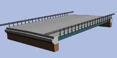
The 3D model was used to prepare drawings and as a basis for the CNC programming.
then welded with 5/16-inch fillet welds to the beams with a tight fit to the top and bottom flanges. Welding was performed using a semiautomatic procedure with E71T-1 flux core (FCAW) wire. About one month after receiving the plans from eSPAN140, U.S. Bridge was able to begin shipping elements to the galvanizer for conditioning. After an internal quality control inspection, the beams were hot-dip galvanized according to ASTM 123 and checked again for coating thickness and any camber loss. The beams were delivered to the bridge construction site and set on October 2, 2013 where it was constructed by local crews. The Jesup South Bridge opened to traffic on November 19, 2013 – just three months after Buchanan County first entered the details into eSPAN140.
Lessons Learned
From a time perspective, eSPAN140 is a handy tool that bridge engineers can utilize to get quick answers and evaluate alternatives directly, zeroing in on feasible options from a wide range of steel superstructure types. From a fabricator’s perspective, eSPAN140 is a helpful program that facilitates good dialogue with a client early on about steel sections, depths of structure, lifting weights, standard details, fabricating processes, corrosions protection, etc. – all the things that make steel a great bridge building material. The detailed design provides a good foundation for a fabricator to know, more or less, how a steel bridge option is going to solve a problem and what the owner can expect in terms of fabricated and installed costs. If it’s a ‘GO’, then U.S. Bridge is quickly on the way to producing bridge members for construction. The Jesup Bridge project is yet another example of the innovativeness of local infrastructure managers across the country. Undaunted by challenges of cost or material, they continue to seek out ways to plan, design and build modern and safe improvements, making the most of limited resources and their own workforce. Jesup South Bridge Demonstration Project Team Donating Companies • U.S. Bridge: Bridge Superstructure
Fabrication, Railing Materials and
Fabrication, Steel Detailing • Nucor-Yamato Steel: Rolled Beams/
Girders • Skyline Steel: H-Piles for the Integral
Abutment System • AZZ Galvanizing: Galvanizing • Nucor Fastener/Ziegler Bolt & Part
Co.: Superstructure and Rail Fasteners • St. Louis Screw and Bolt: Shear Studs • BlueArc Stud Welding: Stud Welding • D-Mac Industries: Stay-in-Place Forms • Gerdau: Memphis Reinforcing Steel:
Rebar • Buchanan County, Iowa:
Installation/Demolition University Partners • West Virginia University: eSPAN140
Development, Design Coordination and Research • University of Wyoming: eSPAN140
Development, Design Coordination and Research • Iowa State University: Research
The goal of the eSPAN140, according to SMDI, is to provide bridge engineers with another tool in their toolbox to develop costeffective solutions for their bridge repair and replacement challenges. While the materials for the Jesup South Bridge were donated, case studies for similar short span bridges have documented a 25% cost advantage when compared to concrete alternatives. Please see www.shortspansteelbridges.org for more information. View a time-lapsed video of the Jesup South Bridge construction process on the Short Span Steel Bridge Alliance website at http://
blog.shortspansteelbridges.org/2013/09/06/
demonstration-bridge-live-webcam/. ▪
About the Short Span Steel Bridge Alliance The Short Span Steel Bridge Alliance (SSSBA) is a group of leaders in the bridge and buried soil steel structure industry who have joined together to provide educational information and design tools for the costeffective design and construction of short span steel bridges in installations up to 140 feet in length. For more information, visit www.shortspansteelbridges.org.
Repair Protect Strengthen
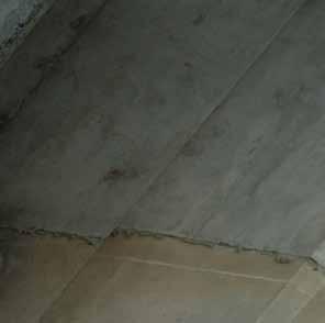
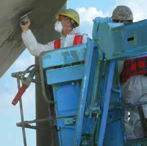
Installation of FX-263 Rapid-Hardening Vertical/Overhead Repair Mortar


Simpson Strong-Tie introduces Repair, Protection and Strengthening Systems for concrete and masonry. Formulated and tested in the lab and proven in the fi eld, our wide-range of repair mortars, coatings, grouts, epoxies, sealants and our FX-70® structural repair and protection system are designed for a variety of applications and environmental conditions. With more than 55 years in the construction industry, you can count on Simpson Strong-Tie to provide practical, cost-effective solutions and personalized genuine service. Get your copy of our new product guide by calling (800) 599-9099 or visiting www.strongtie.com/rps.
Watch the FX-70® Pile Repair Cyclic Testing at www.strongtie.com/videolibrary and subscribe to our YouTube Channel at youtube.com/strongtie and subscribe to our YouTube Channel at youtube.com/strongtie

Design concrete anchoring connections in minutes!
Truspec is a new and free anchor calculation software allowing Architects and Engineers to design concrete anchoring connections in minutes in accordance with ACI 318 Appendix D. This software includes a user-friendly integrated design and implements real-time 3D graphics, color coded results, and value displays in US Customary or Metric Units. Product datasheet, photos, ICC-ES evaluation reports, and specification packages are all included in the Truspec anchor calculation software.
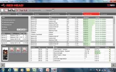

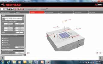
Truspec anchor calculation software users can quickly and easily:
• Create anchor connections in accordance with
ACI 318 Appendix D • Model simultaneous moment forces in x-, y-, z-axis • Model multiple edge and spacing distance configurations • Calculate critical values for total strength design of anchor connections • Select the number of anchor points • Optimize designs across multiple scenarios. • Predict mode of failure for anchor connections • Recommend most efficient anchoring method • Recommend most efficient anchor size • Specify anchoring methods to achieve a desired failure mode
Download at www.ITW-RedHead.com
Tappan Zee Hudson River Crossing
The New NY Bridge Project
By Michael D. LaViolette, P.E.
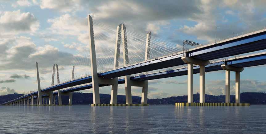
The Tappan Zee Hudson River Crossing (or “New NY Bridge”) is perhaps the largest and most challenging bridge project currently under construction in the US. The project includes two parallel, 3.1 mile-long bridges crossing the Hudson River between Rockland and Westchester Counties, approximately 25 miles north of New York City. Each of the two bridges consists of a 1,200-foot cable-stayed navigation span with common foundations and diverging towers, along with a series of 350-foot continuous, steel girder spans supported on seismic isolation bearings. Construction of the bridges is currently ongoing and is scheduled for completion in 2018 by Tappan Zee Constructors, a design-build LLC composed of Fluor Enterprises, American Bridge Company, Granite Construction Northeast and Traylor Bros. HDR is serving as the lead designer for the project, with significant contributions from Buckland & Taylor, URS, GZA and a diverse array of nearly 40 sub-consultants. The bridge is owned by the New York State Thruway Authority and represents their first design-build project. The project requirements dictated that the primary structural components of the crossing be designed and constructed to provide a 100-year service life before major maintenance will be required. These components include the foundations, substructures, superstructures and bridge decks. The design of bridge systems and components using materials with proven long-term performance characteristics was critical in meeting this requirement. A sophisticated probabilistic approach to the service life was implemented in the design phase to assure a reasonable certainty of satisfying the desired service life criteria. In addition to the demanding design and construction challenges – poor foundation soils, large variation in geotechnical design parameters, moderate seismicity, and ice loading – the bridge is designed to support a future third parallel bridge to carry dual-track railway traffic. The future construction of a commuter or light rail bridge in the narrow gap between the two highway bridges, and without the need for additional foundation construction in the water, required that all foundations and the main span towers be analyzed, and conceptual details developed, to ensure the feasibility of this future load condition. Significant ongoing challenges
Figure 1. New NY Bridge rendering.
facing the design-build team include the very aggressive schedule and the need to maintain the full traffic capacity of the existing bridge throughout the project. The iconic main span structure forms the centerpiece of the new crossing, comprising twin cable-stayed bridges, with 1,200-foot main spans and 515-foot side spans. Each deck will carry four traffic lanes and have wide inner and outer shoulders that provide operational redundancy and flexibility. The main span decks are carried by a semi-fan, parallel-strand, stay cable system anchored to distinctive, outward leaning, V-shaped reinforced concrete towers. The inclined legs of each tower are straight, open box sections connected by single, below-deck cross beams. The future rail transit deck will be supported by a future cable anchorage unit and cross beam that will connect the inner legs of the two towers. The bridge foundations are designed to carry the future rail structure without modification. Each superstructure consists of stiffened steel edge girders and transverse floor beams supporting high performance precast concrete deck panels made composite with the steel using cast-in-place infill joints. To minimize deck width and weight, the stay cables are eccentrically anchored outside of the edge girders.
Substructure
Highly variable foundation conditions at the site represented one of the largest risks to the design-build team. Approximately onethird of the piers on the crossing are underlain by alluvial deposits of normally consolidated organic clay up to 180 feet deep, above lightly over-consolidated glacial lake deposits of varved silt and clay that extend up to 750 feet deep. Due to the extreme depth of these deposits, end-bearing piles were seen as impractical and, consequently, friction foundations consisting of 48-inch diameter, open-end pipe piles extending to 330 feet below the Hudson River were selected. A cast-in-place concrete plug is used to transfer foundation loads to the piles and provide an additional measure of redundant corrosion protection. continued on next page
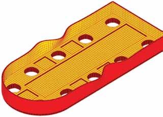
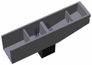
Figure 2. Precast pile tub buckling analysis model (deformations exaggerated). Figure 3. Solid model of precast pier capbeam tub.
The remaining foundations, from Pier 19 to the Westchester abutment, are supported primarily on a combination of 48-inch and 72-inch piles driven to end bearing, with a limited use of 36-inch piles and drilled shafts near the shoreline. Piles are currently being preassembled into 160- and 180-foot subassemblies and driven with both vibratory and hydraulic hammers in order to minimize noise and environmental impacts to surrounding property owners and endangered aquatic species. While the main span tower foundation utilized a precast concrete soffit system, the approach span foundations consist primarily of precast concrete tub-style footings that will be filled with cast-in-place concrete once the tub is placed over the driven piles. The heavily reinforced precast tubs are made composite with the infill concrete through an extensive network of embedded reinforcing and roughened interior surfaces. Extensive threedimensional finite element analyses using SAP and Xtract were performed to investigate lifting and shipping stresses, temporary support conditions, buoyancy and wave action, staged concrete placement and time dependent effects including differential shrinkage. An exaggerated buckling model of the precast pile tub footing is shown in Figure 2.
Attention Bentley Users
Have you received your automatic quarterly invoice from Bentley? Would you like to reduce or eliminate these invoices? Use SofTrack to control and manage Calendar Hour usage of your Bentley SELECT Open Trust Licensing. Call us today, 866 372 8991 or visit us
www.softwaremetering.com
Precast concrete capbeam shells – up to 92 feet long, 10.5 feet wide, and 13 feet deep and weighing 280 tons each – are used for 59 of the approach piers. These tub-shaped precast elements minimize over-water formwork and provide a safe work space for tying of reinforcement (Figure 3). The design features of the capbeam shells were chosen to minimize pick weights, standardize details and to provide fully-composite behavior with the infill concrete. A detailed time-dependent analysis of the staged construction sequence was performed to evaluate the effects of differential creep, shrinkage and locked-in stresses between the precast shell and the cast-in-place infill concrete. Prestressing was provided in the precast pier cap shells to eliminate concrete tension during the second stage cast-in-place infill concrete placement, and to minimize cracking due to long-term differential shrinkage.
Superstructure
A girder-substringer framing system was chosen for the nominal 350-foot approach spans, most of which are arranged in five-span continuous units. This type of system typically provides an estimated cost savings of 10 to 20 percent compared to a multi-girder system for spans in this range. In addition, this relatively light structural system reduces loads on the foundations, a criteria that was particularly important for the western approach spans which are supported on long friction piles. The use of large-scale prefabrication is a critical part of the bridge construction. The Left Coast Lifter, one of the largest floating cranes in North America, with an 1,800 ton lifting capacity, will be used to install pre-assembled two or three girder groups, one full span at a time, which eliminates nearly all temporary falsework in the river, improves worker safety, and saves time and construction costs for operations on the water. Hybrid girders, with girder flange plates consisting of a mixture of Grade 50W and HPS 70W steel, are used to reduce girder weight and maintain high fracture toughness in support of the 100-year service life objective, with due consideration of the limited availability of this material. All thickness changes for the top flange plates are accomplished by varying the web depth and recessing the flange plate changes into the web to accommodate the use of precast deck panels. Girder web depths are transitioned only at the bolted field splice locations. Precast concrete deck panels, approximately 12 feet long and varying from 42 feet–3 inches to 46 feet–9 inches in width, utilize a single longitudinal closure pour between panels. The panels consist of high-performance concrete with 5 ksi compressive strength and mild reinforcement (no post-tensioning). In order to eliminate the need for form stripping, the transverse joints feature a permanent, integral bottom form ledge. The joint utilizes overlapping hairpin reinforcement projecting from each adjacent panel and a number of transverse reinforcing bars that are inserted through the hairpins to provide a continuous mechanical connection between panels. To validate the reinforcement-only option for the cast-in-place deck joints, a SAP2000 finite element model was used to evaluate the service-level stress condition of the bridge deck for a fully continuous superstructure. The SAP2000 analysis included staged construction, time-dependent effects and non-linear post-cracking behavior of the reinforced concrete deck and joints.
Structural Additions
In consideration of the extensive public involvement and visual quality processes for the New NY Bridge, the project requirements included the incorporation of a shared use path (SUP) for pedestrians and bicycles as part of the permanent westbound bridge configuration. In addition, one of the intermediate construction stages includes a period
of time when westbound vehicular traffic is allowed to utilize the future SUP portion of the cross-section as a travel lane. Additional special structure details include:
Belvederes – the westbound bridge incorporates six 12- x 60-foot belvedere structures cantilevered from the north face of the exterior girders. The belvedere structures are supported through a cantilever connection from the exterior girder web and rigidly braced to the interior girder to eliminate torsional girder deformations.
Permanent Crossovers – will be provided between the eastbound and westbound structures at three locations along the crossing to facilitate public evacuation and turnaround capabilities in the event of an extended delay from a traffic obstruction. These simple-span structures are supported on brackets attached to the interior girders of the opposing bridges.
Conclusion
Perhaps the greatest benefit of the designbuild method is that it allowed the engineers to interact directly with the contractor throughout the design phase. The innovations resulting from this collaboration not only met all the project requirements and design criteria, but did so by incorporating the contractors’ means and methods to generate cost-savings and provide the greatest schedule benefit. The New NY Bridge project is an outstanding example of using the design-build contracting method to deliver an innovative and cost-effective project. The Tappan Zee Constructors team worked together during the design phase to validate and compare various structural systems, ultimately developing a cost-effective design solution that is quickly being realized as a new, iconic bridge for the New York area.▪
All photos courtesy New York State Thruway Authority.

State-of-the-Art Products
STRUCTURAL TECHNOLOGIES provides a wide range of custom designed systems which restore and enhance the load-carrying capacity of reinforced concrete and other structure types, including masonry, timber and steel. Our products can be used stand-alone or in combination to solve complex structural challenges.
V-Wrap™
Carbon Fiber System
DUCON®
Micro-Reinforced Concrete Systems
VSL
External Post-Tensioning Systems
Tstrata™
Enlargement Systems
Engineered Solutions
Our team integrates with engineers and owners to produce high value, low impact solutions for repair and retro t of existing structures. We provide comprehensive technical support services including feasibility, preliminary product design, speci cation support, and construction budgets. Contact us today for assistance with your project needs.
Michael D. LaViolette, P.E., is a Principal Project Manager with HDR Engineering in Omaha, NE. He recently served as the Deputy Design Manager for all structures design on the Tappan Zee Bridge. In addition, he currently serves as Chairman of TRB Committee AFH40 – Construction of Bridges and Structures. For further information on the project, Michael can be contacted at mike.laviolette@hdrinc.com. www.structuraltechnologies.com +1-410-859-6539
To learn more about Structural Group companies visit www.structuralgroup.com DUCON® trade names and patents are owned by DUCON GmbH and are distributed exclusively in North America by STRUCTURAL TECHNOLOGIES for strengthening and force protection applications. VSL is the registered trademark of VSL International Ltd.
Building the First By Peter Davis Movable Bridge in Malaysia
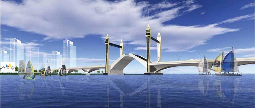
Figure 1. Rendering of the final bridge design concept.
Malaysia is a country which became independent from the British is 1957 and has been developing its economy and infrastructure ever since. Malaysia is the 3rd largest economy in Southeast Asia and 29th worldwide based upon exports of natural and agricultural resources and petroleum. It has a large manufacturing sector; however, one of the economic goals is to increase tourism. Kuala Terengganu is a city on the eastern side of the Malay Peninsula approximately 500 kilometers (311 miles) Northeast of Kuala Lumpur. This side of the peninsula is less developed and presents opportunity for tourism based upon the beaches and interior habitat. This city of 400,000 is at the mouth of the Terengganu river delta. In order to facilitate economic and tourism growth in the area, a bridge is planned to connect the North and South districts of the city. This bridge will be 672 meters (2200 feet) long with a movable span crossing the navigation channel. The proposed bridge has pre-stressed concrete approach spans and a twin leaf bascule span over the 50 meter (164-foot) navigation channel. While bridges in the United States are used strictly for transportation, this structure will provide mobility across the river and will also serve as a tourist attraction, allowing viewing of the Monsoon Cup races held locally as a major sporting event. The structure is to serve as an icon of the area and will fit the context of the local architecture.
The Bridge
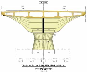
This 672 meter (2200 foot) long bridge carries 4 travel lanes, sidewalks and a median barrier for a width of 23 meters (75.5 feet) (Figure 2). The design speed is 60 KPH (35 MPH) and has a maximum 5% grade. The bridge will have 9 spans plus embankment approaches. Spans 1 and 9 (Figure 3) are designed using concrete beams to provide a minimum under-clearance of 2.2 meters (87 inches) to allow cars to be parked. This parking area will be utilized by the public to both enjoy the waterway as well as access to the amenities at the bridge. Spans 2 thru 4 are pre-stressed concrete box sections of 53 meters (173.9 feet) and 50.5 meters (165.7 feet) in length. These box sections are supported on drilled shafts and cast-in-place piers (Figure 4). For this structure, there is a high degree of consideration for the aesthetic characteristic to provide a modern image, as well as retain local architectural characteristics. Movable Span The movable span provides a 50 meter (164-foot) navigation channel with infinite vertical clearance. The clearance under the bridge when closed is 12 meters (39.4 feet). Contractors in Southeast Asia do not have experience with movable bridge construction. For this reason, it was important to simplify the construction as much as possible while maintaining the required functionality. The bascule leaves will be constructed from steel with a concrete roadway surface. The leaf design utilizes a three girder system for redundancy. Each leaf is 44.9 meters (147 feet) long and is supported by 6 trunnion bearings. The leaves weigh approximately 1600 tonnes each. The
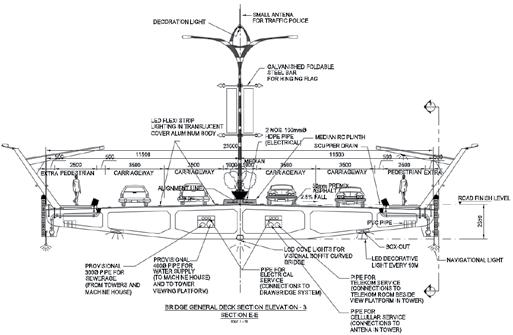
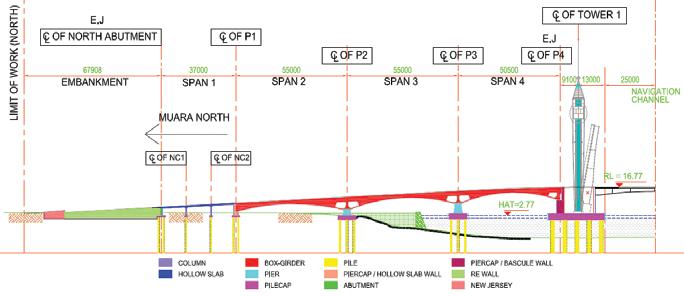
Figure 3. Approach span configuration.
trunnions are supported on towers within the enclosed bascule piers. These piers are supported by thirty 1830 mm (72-inch) diameter drilled shafts. Since the alignment of the leaves and machinery is very critical, a decision was made to use hydraulic cylinders to operate the spans. The alignment requirement for these cylinders is more forgiving than for traditional mechanical gearing. Three cylinders per leaf are used allowing for redundancy such that, if a cylinder fails, the bridge will remain operational. Each cylinder has a bore of 458 mm (18 inches) and a stroke of 3390 mm (133.5 inches). When the two leaves are closed, they are locked together with four “lock bars”. These lock bars are high strength steel 254 mm wide and 382 mm high (10- x 15-inch). The bars are driven and pulled using linear actuators. The bridge is controlled by a conventional relay-based system with a computer operator interface. This approach was taken so that a qualified electrician can repair the control system to maintain operation even if the computer-based system fails. The computer system provides both the operator interface as well as a monitoring system for the hydraulic power supplies and the control system function. A programmable decorative lighting system will be installed to highlight both the fixed and movable spans. Towers The signature features of the bridge are the towers and the public space created by the connecting structure (Sky Bridge). The towers are 72.5 meters (238 feet) tall not including a 16.6 meters (54.5-foot) antennae. The towers replicate the minarets of mosques and provide a Malaysian version of the Tower Bridge in London. The Sky Bridge public space is 1118 square meters (12,000 square feet) between each pair of towers. Elevators are provided to access the Sky Bridge space as well as stairs for emergency evacuation. The Sky Bridge spaces are two stories, allowing food preparation and HVAC equipment to be located below the public space. Both the North and South approach span roadways have been widened to provide a drop off and loading lane for visitors to the bridge.
Construction
The construction contract for the bridge was awarded in August 2014, with expected completion in 2017. Since the local contractors do not have a history of movable construction, the design team prepared shop drawing level design documents as well as a detailed construction sequencing. The construction sequence will include working sessions with the contractor such that they become aware of the specific challenges of installing, aligning and balancing the bascule leaves. In order for the bascule leaves to be properly aligned, key checks will be performed during their erection. These checks include monitoring deck and counterweight concrete weight, and making adjustments during pouring. In addition, the pouring of the approach span deck will be one of the last items to be constructed so that a smooth transition between the spans is achieved. It is a rare opportunity to participate in such an elegant project.▪
Peter Davis (pete.davis@hdrinc.com), a licensed mechanical engineer, has 39 years of experience in the inspection, design and construction of heavy infrastructure including locks, dams and movable bridges.
Overcoming Challenges
Erecting a Long Single Span Curved Steel Girder Bridge
By Michael H. Marks, P.E.
Figure 1. Completed structure.
In 2009, the New Jersey Turnpike Authority began work on a 35 mile widening from Exit 8A to Exit 6 consisting of extending the dualization of the roadway for car and truck lanes. Th e fi nished roadway will consist of six (6) lanes in each direction. Five (5) interchanges were reconstructed and/or reconfi gured, along with the replacement or widening of all bridges along the route. A total of 23 contracts were let for the project with an approximate cost of $2.5 billion.
Bridge Description
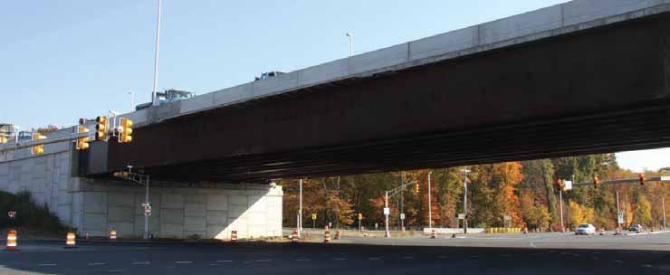
As part of the reconstruction of Interchange 8 in East Windsor, Mercer County, New Jersey, the new Ramp TW/WT needed to cross Route 33. To accomplish this, a new single span bridge was required. Th e bridge consists of a simple span superstructure with a cross section of eleven (11) curved steel welded girders spaced at 8 feet 3 inches, supporting a cast in place 8.75-inch deck. Each girder has a web thickness of ⅞ -inch and depth of 129 inches. Flange size varies from 26 x 1½ inches to 28 x 3 inches. Th e span length of the structure is approximately 257 feet 8 inches along its baseline between Girders 5 and 6. Th e out-to-out width of the bridge deck is 87 feet 10 inches, consisting of an approximate 36-foot wide roadway for eastbound traffi c and a 47-foot 6-inch wide roadway for the westbound lanes. Th e horizontal radii of the girders vary from approximately 1763 feet to 1845 feet, with the abutment bearing lines being radial. Girders 9 through 11 on the outside of the curve have signifi cantly larger fl anges than Girders 1 through 8 to accommodate the increased load due to the curvature. Between the girders, cross frames composed of steel angles are spaced at approximately 24 feet (Figures 1 and 3).
Steel Erection Issues
EIC Group LLC (EIC), Fairfi eld, NJ, was retained by the steel erector subcontractor, Archer Steel Construction (Archer), Manalapan, NJ, to develop the erection plans and procedures for the installation of the steel girders. Th e erection of this bridge, thought to be the longest single span curved steel bridge east of the Mississippi, presented several engineering and construction challenges: • Th e curved girders had to be fi eld spliced requiring the webs to be as plumb as possible for fi eld fi t. Th is necessitated the need for very exact center of gravity calculations and pick point determination. • Due to the large span length, radius and depth of girder, the stability of the girders both during the pick and at each stage of the erection had to be carefully analyzed and maintained. • Th e bridge was constructed above a heavily traveled and active roadway, resulting in very short work windows and lane closure times.
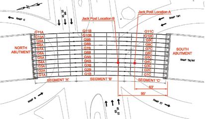
The steel girders were composed of three (3) segments (A, B and C) spliced together to make up the overall girder length (Figure 3). This long length made the erection of the completely assembled beam as a single lift, either alone or in pairs, not feasible both from a weight and stability point of view. Therefore, the structure had to be constructed by erecting individual segments. Based on engineering and construction issues over the roadway, it was decided to erect the structure by first erecting one end segment and supporting it on the abutment and towers. Next, the other segments would be assembled on the ground and erected as a unit. This unit would then be spliced in the air to the first erected segment and released. Figure 3. Framing plan and jack post locations. The southern segment (segment C), approximately 80 feet long, was the only portion of the structure not directly above the Typically, for a curved steel girder bridge, it is desirable to erect from active roadway. Therefore, a tower bent was proposed at the location the outside of the curve towards the center. As the curved girder is of the B/C splice and then the C segments erected and supported erected, it tends to rotate towards the outside. The result of this rotaby the South Abutment and the tower bent. It was planned that all tion is that the web will be slightly out of plumb, but leaning away eleven (11) towers would be set up, one for each girder line, followed from the center of curvature and next inner girder to be erected. This by the erection of all C segments. To satisfy stability requirements, outward lean makes it easier for the erector to connect to the cross the first 10 segments would be ground assembled and then erected frames of the next inner girder because the web is facing “up”. After as pairs. The last segment would be lifted as a single and connected the inner girder is connected to the crossframes, it can then be lowered to the cross frames from the previously erected pair. into place. If the sequence were to go from inside to outside of the After the C segments were complete, the A/B segments would be radius, then the web would be facing “down” due to the girder roll, ground assembled and then erected as pairs. They would then be air and would make it more difficult and time consuming to connect to spliced to the C segments and lowered onto the North Abutment. the next girder. This is especially critical if there is a traffic shutdown Again, the final girder would be erected as a single. and time is of the essence. continued on next page
ADVERTISEMENT–For Advertiser Information, visit www.STRUCTUREmag.org
Toll-Free: (866) 252-4628 12080 SW Myslony St. Tualatin, OR 97062 info@albinaco.com www.albinaco.com YOUR BENDING EXPERTS
75th
ANNIVERSARY!
Servicing the Steel Industry Since 1939 -Angle -Flat Bar -Square Bar -Wide Flange -Channel -Square Tubing -Tee -Rectangular Tubing -Round Tube & Pipe -Round Bar -Rail -Plate
Hwy 36 Bridge Denver, CO. Dry Creek Bridge Denver, CO.
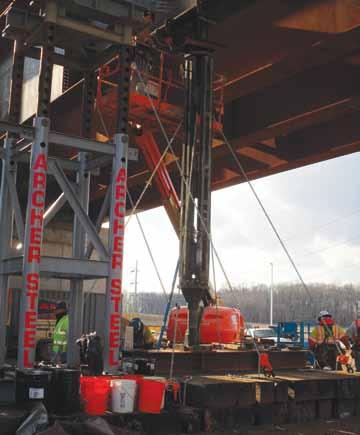
Figure 4. Jack Post A beneath Girder Line 4 and tower for support of Girder Line 5.
However, for single span curved bridges, especially those as long as this structure, this sequence is difficult to achieve. The abutments at each end of the span are constructed radially, thus reducing the opening the erector has to work with when setting each successive girder towards the center. This “pinching” effect will hinder the erector’s ability to swing the girder into place. Because of this and assembly area limitations, Archer needed to erect outward and therefore the roll of the girders had to be precisely controlled. It was planned to set all eleven girders on the towers to control the outward roll so the cross frame connections could be made with minimal effort. Once all girders were erected and plumbed, then all towers would be lowered simultaneously and the structure allowed to assume its deflected position. The pieces to be lifted ranged in weight from 56,000 pounds for the single C segments to 380,000 pounds for the paired A/B segments. Manitowoc 999 and the American 2250 crawler cranes with capacities of over 200,000 pounds were to be used for the erection. The rigging consisted of a 60-foot segmented pipe spreader beam designed by EIC specifically for Archer Steel, 16-foot pipe spreader cross beams, and wire rope slings with conventional beam clamps. The towers, also specifically designed by EIC for Archer, are 4-legged prefabricated telescoping pipes with steel grillage beams on top. Jacks were specified for elevation control and height adjustment.
Erection
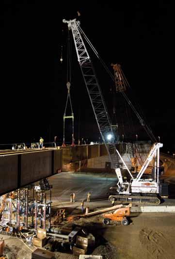
Erection was started in December of 2012. The first four towers were set up beneath segment C for Girders 1 to 4 at their designated locations. Due to availability issues of the remaining towers, it was decided to erect the first four girders in their entirety (all segments) and when complete, the remaining towers would be set up and the last 7 girder lines would be constructed. Girders 1-4 The C segments of Girders 1 and 2 were then lifted in a pair by the 2250 crane using a pipe spreader and cross beam rigging arrangement, and then walked into position on the south abutment and towers. This was repeated for Girders 3 and 4. Next, during a complete road closure, the corresponding A/B spliced pairs were lifted and walked using both crawler cranes from the assembly area into an intermediary position in the closed roadway. They were set down on temporary mats while the cranes rotated their tracks into a new position. Once aligned properly, the cranes picked the piece again and crawled forward, air spliced the piece to the C segments and set on the abutment (Figure 2, page 32). This was repeated for the remaining A/B pair. Archer plumbed the girder webs carefully and then connected all cross frames and fully tightened the bolts. At this point, many of the remaining towers were still unavailable and thus could not be set up as planned. Due to time restrictions, it was decided to lower the towers that were holding G1 to G4. It was expected that the girders would rotate and that there may be difficulty connecting the next outer girder, as now the web would be facing down. To prevent this problem, EIC developed a solution that would utilize supplemental jacking posts under the erected girders while the towers were moved into the new positions. The proposed solution was to determine the downward deflection that would occur due to the girder roll and then install jacking posts at appropriate locations to jack the 4-girder assembly back up into web vertical position. Then the next 4 girders would be installed and connected to the first 4 girders. The towers would then be lowered again and moved. However, with eight girders in place, it was anticipated that the roll would not be significant enough to affect the erection of the last 3 girders. EIC in conjunction with BSDI of Coopersburg, PA performed a 3D finite element analysis of the four and eight girder systems. It was determined that after the towers were removed, the outer girder would drop a maximum of approximately 8.4 inches at midspan with almost 9 inches of lateral outward movement of the top flange. To jack the beams to vertical and remove the deflection, it would have been desirable to place the jacking post at the midspan as this would have resulted in the minimum jacking force. However, due to the active roadway, this was not possible. As a result, EIC decided to utilize two posts, one at 63 feet from the South abutment (Location A) and the other at 95 feet from the South Abutment (Location B) under G4 only. Due to jack stroke limitations, the two posts would work together to allow one jack to be de-pressurized while the other jack was raised to continue jacking. EIC’s analysis revealed that a force of approximately 200 kips would be required at Location A in order to raise the four girders and achieve a plumb web position. For the jacking posts, Acrow Shoring Superprops were utilized supported on timber foundations (Figure 3). Upon completion of the analysis, the towers were lowered allowing the four girder system to deflect. Measurements revealed deflections and girder roll to be almost exactly as predicted by the 3D model. Next, the jack at Location A was pressurized to lift the girders back to a web plumb position. The load required was also very close to predicted, approximately 200 kips. Also, as predicted by the model, jacking brought the girders fully back to the pre-release position and completely eliminated the girder roll. While the jacking was occurring at the Superprop, towers were moved and set up under the remaining seven girder lines. An additional three towers became available, so no further intermediate lowering was required. After the remaining girders were erected in similar fashion to the first four, all towers and the Acrow Superprop were

Figure 5. Erected Girder Lines 1-4 with jack posts in place.
lowered simultaneously to allow the fully assembled bridge to deflect downward into its steel dead load only position (Figures 3, 4 and 5).
Conclusion
Michael H. Marks, P.E., is founder and principal of EIC Group LLC, a specialty bridge engineering firm based in Northern New Jersey. He may be reached at mmarks@eicgroupllc.com.
The erection of single span curved bridges, especially with spans as long as Ramp TW/WT, requires careful planning and analysis to accommodate the large deflections, girder roll, and erection geometry restrictions. However, as typical in most construction projects, sometimes site constraints or issues with material availability require fast, economical and innovative solutions during construction. By performing a rapid and detailed 3D analysis of the partially constructed structure, the Archer/EIC team was able to evaluate the bridge behavior and anticipate response in an unconventional supported position in order to accommodate the contractor’s material availability. The bridge erection was completed within the allotted timeframe with no impact on the overall project schedule.▪
Project Team
Owner: The New Jersey Turnpike Authority Engineer of Record: Gannett Fleming Inc, Mount Laurel, NJ General Contractor: Ferreira/Crisdel Joint Venture,
Branchburg, NJ Steel Erector: Archer Steel Construction, Manalapan, NJ Erection/Construction Engineer: EIC Group LLC, Fairfield, NJ Steel Fabricator: High Steel Structures, Lancaster, PA Jacking Post Supplier: Acrow Corporation of America,
Parsippany, NJ
ADVERTISEMENT–For Advertiser Information, visit www.STRUCTUREmag.org
Helical Pile Technology
Exclusive Patented Technologies for Foundation Solutions
ESR-1854
ICC-ES Recognized as Code Compliant to meet International Building Code
Patented threaded connection provides a higher torque rating to penetrate dense soils; Rigid connections to maximize lateral capacity

Up to six different pile diameters in stock to provide the most economical solution to meet any design load

Custom fabrication of piles & brackets for residential, commercial, industrial, and utility solutions


Watch Our Helical Installation Video: ramjack.com/HelicalPiles 888.332.9909


Patented threaded connection; Strongest, most rigid in industry
Thermoplastic Helical Piles resist corrosion/ environmentally friendly
Helical Piles stamped into true spiral shape; Penetrates load- bearing strata


