9 minute read
the Monongahela river (Wabash) Cantilever
The Pittsburgh, Carnegie & Western Railroad, commonly called the Wabash line, had tracks in Illinois, Indiana and Ohio generally running southwesterly from Toledo to St. Louis, but there was interest to connect to Pittsburg as a step in becoming a transcontinental railroad. The plan was to connect with the tracks of the Wheeling and Lake Erie Railroad at Toledo and then run southeasterly towards Wheeling on the Ohio River, where a short branch line would be built from Pittsburg Junction to Mingo on the Ohio River. From that point, there were two options: The first was to cross the Ohio River on a major bridge and then cross the mountainous regions of the panhandle of W. Virginia and south western Pennsylvania and enter into Pittsburg with a major bridge across the Monongahela River, the southern boundary of Pittsburgh. This line would require many bridges and tunnels, but it was a direct east-west line to the City. The second route would take the line along the west bank of the Ohio River northerly to a large bend in the river, and then to the south and east to Pittsburgh with a major bridge over the Allegheny River to their terminal. This line was cheaper to build but longer in length. The Bridge Company, called the WabashPittsburgh Terminal Company, chose the southern route which meant trains had to cross the Monongahela and Ohio Rivers with two large

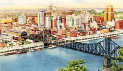
Completed bridge, terminal on left side of post card.
Historic structures
significant structures of the past
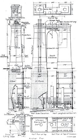
bridges, the larger one across the Monongahela. The president of the line, Joseph Ramsey, in association with George Gould (son of Jay Gould) had great plans for the line and felt the traffic generated would more than pay for the expensive construction, then estimated at $20,000,000. Ramsey/Gould needed permission to enter Pittsburgh by way of a bridge over the Monongahela River and to build a terminal in the heart of downtown Pittsburgh. The city was considered Pennsylvania Railroad country at the time. Even though “… besieged by rivals, arraigned by the city, delayed by the The Monongahela River (Wabash) Cantileverpolitics of municipal councils, hindered by unexpected natural obstacles and by accidents, strikes, and even peremptorily stopped by the Supreme By Frank Griggs, Jr., Dist. M. ASCE, Court of Pennsylvania, they gained an entrance D. Eng., P.E., P.L.S. into Pittsburgh.” The City Council, at the time unhappy with the Pennsylvania Railroad, approved an ordinance on February 4, 1904. The War Department approved a bridge height of seventy feet over the Monongahela River. The railroads chief engineer, J. W. Paterson, picked the firm of Boller & Hodge to design both bridges. Alfred Pancoast [A. P.] Boller and Henry Wilson Hodge, both Rensselaer Polytechnic Institute Dr. Griggs specializes in the graduates, had excellent experience in designing restoration of historic bridges, bridges, but had not designed any major canti- having restored many 19 th Century lever bridges at the time. cast and wrought iron bridges. He It was necessary to build a bridge which did was formerly Director of Historic not obstruct the channel during construction, Bridge Programs for Clough, and had spans long enough and high enough off Harbour & Associates LLP in the river surface so as to permit continued river Albany, NY, and is now an traffic. The answer to this set of constraints in the independent Consulting Engineer. early 1900s was a cantilever bridge. Dr. Griggs can be reached at The foundations for the main piers, placed by fgriggsjr@verizon.net. means of pneumatic caissons, were located at the edge of the low water line and were set on solid slate rock about 42 feet below low water level. The anchorages were also set on solid rock at about the same elevation, and constructed in a manner similar to other cantilevers with steel eye-bars embedded in concrete. Boller & Hodge, however, had the lower part of their anchor rods cast rigidly in the concrete of the anchorage and the upper part contained in a well which permitted them to pivot and permit horizontal movement
of the end of the anchor span. Usually this movement was permitted at the top of the anchorage pier by having an exposed link from the pier at the end of the anchor arm. The bridge was designed to carry two tracks, and at the time of its completion would be the longest cantilever in the North with a span of 812 feet. At the time of its design, the Blackwell’s Island (Queensboro) Bridge over the East River in New York was being re-designed and the Quebec Bridge over the St. Lawrence River was still under design, so George Morison’s Memphis Bridge across the Mississippi River, with its 790-foot span, was the longest cantilever span railroad bridge. The superstructure was unprecedented in terms of its size and complexity. Boller and Hodge wrote, given the site constraints, …the anchor and lever arms of the cantilever are unequal, and are so proportioned that under dead load only, the reaction at the anchor piers is reduced nearly to zero. In the suspended span and at the ends of the cantilevers arms, the panels are uniformly 30 feet long, but where the truss is deeper, near the shore pier, the panels are increased to 40 feet, so that the main diagonals cross the two panels throughout at nearly uniform inclination of about 45 degrees and the difference in panel lengths is not noticeable. As the stresses in the main vertical posts over the shore piers are very large, it was deemed advisable to make each post in two parallel halves, which were separated 12 feet on centers and connected by horizontal longitudinal braces without diagonals, thus making a sort of narrow tower which is more easily constructed, and permitted a reduction of stress in the pins, more convenient connections for the assembled members, and a better distribution of the loads on the masonry. The anchor span lengths were 346 feet, the cantilever arms were 220 feet and the suspended
StruWare, Inc
Structural Engineering Software
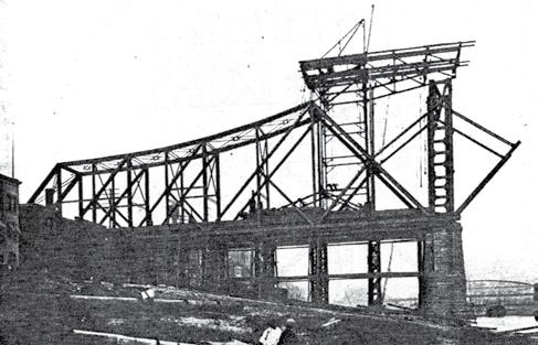
The easiest to use software for calculating wind, seismic, snow and other loadings for IBC, ASCE7, and all state codes based on these codes ($195.00). CMU or Tilt-up Concrete Walls with & without openings ($75.00). Floor Vibration for Steel Bms & Joists ($75.00). Concrete beams with/without torsion ($45.00). span was 360 feet. The main diagonals crossed two panels, with additional short diagonals as necessary. The top chord of the anchor and cantilever arm was made of steel eye-bars that were the largest ever used in a bridge in the United States up to that time and were made out of plates 14- by 2-inches in section. The American Bridge Company, which received the contract to supply and erect the steel, built a new plant at Ambridge, Pennsylvania especially to form the eye-bars. The trusses were spaced 32 feet apart to accommodate the two tracks. With the span lengths fixed, the loads determined and the truss geometry fixed, the structure was statically determinate. Boller & Hodge used graphical analysis to determine the member forces for purposes of design. Instead of using actual loads at each panel point, they developed, possibly for the first time, the use of unit loads at each panel point. The technique is simple, straight forward, and for anyone who has actually prepared a “strain (load) sheet” for other than a simple truss knows that it was a time-saver. The anchor spans were erected on false work and the cantilever arms and suspended span by cantilever methods. Boller and Hodge, working with American Bridge, laid out a detailed plan

Wabash Bridge anchor span and tower under construction.


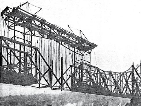
Truss pattern.
of erection, “…the operations were performed in accordance with eighteen diagrams numbered and lettered so as to show the sequence of all steps and having notes directing the blocking, wedging and any special provisions to be made at special joints.” Th ey used two, specially designed, steel travelers so that work progressed simultaneously from both sides of the bridge. Th e travelers ran inside the main trusses and had a reach of a panel and a half. Most of the steel was delivered to the bridge site by barge from a staging yard located two miles upstream. Th e result of this planning was a bridge that went together like, as they said at the Kentucky River Bridge, “a Springfi eld musket.” Th e erection went smoothly except for a tragic accident in which a bottom chord buckled under the weight of the traveler, cantilever arm and half of the suspended span. Ten men were killed when the suspended span was nearing completion on October 19, 1903. Th is accident occurred “… while the traveler was working well within its capacity, the lower chord of the cantilever truss collapsed and the over hang revolved downwards against the bridge trusses. After careful investigation the only reason to which failure can be ascribed is that the bottom chord of the overhang in the panel next to the traveler tower had become injured a short time before by a blow, probably from the 2-ton steel ram used in driving pins.” Th is blow apparently buckled some of the lattice bars and forced the chord out of position. When it was subject to live load the stress was greatly increased by the eccentricity and the member failed under a static load, well within its normal capacity and much less than was safely sustained before and afterwards by it and the duplicate traveler on the opposite side of the river. Other than this, the erection of the bridge by workmen of the American Bridge Company was rapid and safe. Th e bridge weighed over 14,000,000 pounds, with the largest member lifted being the main vertical posts at the shore piers that were fabricated in two parts. When built in 1904, the bridge exceeded the span of the Memphis Bridge by 22 feet and held the title of the longest railroad bridge in the country and third longest in the world. It retained that status until the Queensboro Bridge across the East River opened in 1909. Th e line was abandoned and the bridge removed in 1948.▪
GEOPIER IS GROUND IMPROVEMENT.®
The alternative to deep foundations.
DESIGN-BUILD SOLUTIONS FOR ALL SOIL TYPES
SEND US YOUR PROJECT DATA
Work with Geopier’s geotechnical engineers to solve your ground improvement challenges. Submit your project specifications to receive a customized feasibility assessment and preliminary cost estimate at geopier.com/feasibilityrequest.
800-371-7470 geopier.com info@geopier.com
©2015 Geopier Foundation Company, Inc. The Geopier® technology and brand names are protected under U.S. patents and trademarks listed at www.geopier.com/patents and other trademark applications and patents pending. Other foreign patents, patent applications, trademark registrations, and trademark applications also exist.


