52 minute read
STRUCTURAL REHABILITATION


renovation and restoration of existing structures
Life before ICRI
By Donald Kearney
Don Kearney is a founding Principal of Contracting Specialists Inc. (CSI) with offices in Boston, DC and Pompano Florida. Don is a chartered member of the Institution of Engineers of Ireland (CEng MIEI) and the Institution of European Engineers (Eur Ing) and can be reached at dkearney@ contractingspecialists.com. This is the second in a two-part article on repairing aging, normally reinforced, concrete garage structures existing in aggressive weather environments. Part 1: The Designer’s Perspective was published in the April 2016 issue of STRUCTURE® magazine.
The Contractor’s Perspective
Over the last 30 years, the author worked in the concrete restoration industry as an engineer, owner’s representative and, for the past 20 years, on the contracting side. In that time, these experiences provided valuable perspectives of all sides of this issue, but more importantly a true appreciation of the practicalities that need to be considered in the field of concrete restoration. Many of the earliest garages constructed in the first part of the twentieth century are no longer in existence, having been demolished due to age or re-development activities or even transformed into office space over the years. A few have survived without extensive remodeling or remediation; and these garages offer a glimpse, like a museum, into the history of the concrete repair industry in its innovations, failings and successes over the course of time. Repairs performed using gypcrete, drypack, early bag mixes, epoxy mortar and even polyurethane base coat (extended with sand) are still evident today. Too often, people jump to conclusions as to the failure of a material or application technique without investigating the true causes. There is not a single material, nor application process, in use today that has not endured failures. In these cases, a systematic analysis of all materials and processes is required to determine the root cause. Many organizations, specifically the American Concrete Institute (ACI) and International Concrete Repair Institute (ICRI), have devoted significant amounts of time and resources in preparing guidelines for good practices and procedures for the concrete repair industry. These guidelines should be referenced and consulted with any concrete repair project.
Bid and Pre-Construction
Specialty contractors in the field of concrete repairs generally get introduced to a project at the budget or subsequent bid phase. Design engineers will at times seek a contractor’s assistance with project budgets or help with phasing of complex garages. Time allocated to the bid process is limited, dependent upon the size and complexity of the projects, as this is a non-compensatory task. Engineers who have spent weeks and possibly months on the design assume that contractors have spent a similar amount of time in preparing their bid. With a bid period of generally two weeks, allotted time can be measured in hours or, at maximum, days. When bidding a project, the restrictions imposed can be as important as, and at times of greater significance than, the work itself. Phasing, work hours, traffic control, site logistics, and schedule can have significant impacts on the price. The owner and their consultant have a variety of contract types at their disposal for bidding purposes. Unit Price Contract The Unit Price contract is the most common form of contract adopted by the experienced consultant. Site soundings, testing and sometimes exploratory demolition provide the consultant with sufficient information to develop a detailed scope and bid quantities. A well-defined scope and working parameters will generally provide very competitive bids from experienced contractors. This is the contract form primarily recommended by ICRI and forms the basis for their technical bulletin Guide for Methods of Measurement and Contract Types for Concrete Repair Work. Time and Material Time and Materials contracts are best suited to emergency work, where the consultant has not been afforded the time to perform due diligence and develop a proper scope of work. Lump Sum Lump Sum contracts are rarely used in the concrete repair industry, as the work scope cannot be fully established and the potential for latent conditions makes this a very risky proposition for a prospective contractor. In the event that an experienced contractor is presented with this situation, a large contingency is generally incorporated which in turn is bad for the owner. The alternates of an aggressive or underbid proposal from the contractor will quickly result in dissatisfaction among all parties. The Players As with any contract, a successful outcome is heavily dependent upon all parties working closely together and the owner obtaining a successful end product, while at the same time the contractor makes a fair market value profit. Owners typically want a quick start to their garage repair projects, so the pre-construction process (which includes permitting, submittals, schedules and phasing plans) needs to be expedited. The contractor also needs to review the documents, drawings and details carefully, and issue any RFIs where they foresee problems or conflicts.
Upon capture of the garage project and the first work phase, it is critical that the contractor mark out all repair areas in conjunction with the Engineer of Record (EOR). This allows for more accurately sequenced and scheduled work. Of equal importance is to establish what the deteriorated areas are exhibiting and to see whether alterations in approach to the specified repairs are required. Too often, inexperienced engineers adhere strictly to the specification as opposed to using it as a guide. A lack of experience and recognition of varying conditions can result in a poor repair strategy. The use of boiler plate specifications, not specific to the job at hand, can also be problematic. The author has seen specifications where a clause has been inserted restricting demolition hammers to 12 pounds. The impracticality of this is akin to cutting your lawn with scissors. In both cases it can be done, but the cost and time impacts are prohibitive.
Identifying Repair Areas
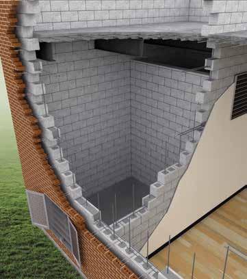
Sounding and demarcation of defective areas of concrete are generally performed by chain
Congested reinforcing over a beam after demolition.
drag, with more precise soundings performed with a hand held hammer. Markings are generally located approximately 6 inches beyond the delaminated edge to ensure that the extent of unsound concrete and any suspect areas are captured in the repair. The first dilemma often faced by the EOR is curtailing the quantities while still ensuring that sufficient concrete is being removed to achieve a durable repair. Patches should follow a regular shape and acute angles should be avoided. Many times concrete demolition is not permitted beyond the corroded length of the bar in an effort to minimize quantities, but this may result in development of accelerated deterioration at the new bond line (often referred to as the halo effect). Too often, a review of concrete repairs previously undertaken in a garage indicates deterioration of areas just beyond, and sometimes extending back into, recently installed patches. continued on next page
ADVERTISEMENT–For Advertiser Information, visit www.STRUCTUREmag.org
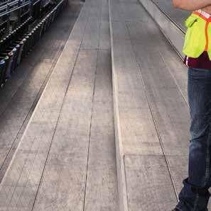
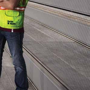
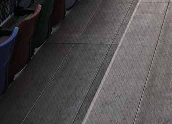
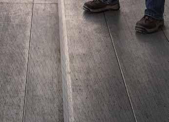
For most contractors, it is both preferable and more efficient to sawcut in advance of the main demolition. Care needs to be exercised with this approach, as nicking or cutting of the embedded reinforcement can cause additional problems and the need for additional repairs in the form of supplemental reinforcement. Although the intent at the time of construction was to provide a minimum of 1 to 1½ inches of concrete cover, deficiencies in cover have in many instances initiated the problems being observed. Therefore, spot checks on the depth of reinforcement are critical if this procedure is adopted. If the cover to the reinforcement is predominantly less than ¾ inches, then the EOR will have to be satisfied with a perimeter cut of less depth than specified. All floor demolition is different, and production can vary significantly depending on the type of equipment utilized, the strength of the existing concrete and the density of embedded reinforcement. Generally the restriction for demolition of suspended floor slabs is 30 pound hammers. Different types of chisels for the pneumatic equipment will also be utilized to determine best results. The EOR also needs to evaluate the existing reinforcing for loss of section to determine whether supplemental bars are required or, alternatively, whether any of the existing damaged reinforcement is redundant and can be removed without replacement. Hydro-demolition of concrete has found a place in the industry but, like many other means and methods, it is suited to certain projects and is constrained in many instances because of logistical issues. There is no doubt that hydro-demolition produces a better surface profile and cleans the bars of contaminants. However, water containment, treatment, clean up and protection of fixtures, along with price, can make it uneconomical unless large areas are available at one time.
Horizontal Deck Repairs
Once the repair areas have been demolished and fine chipped, the process for final preparation in advance of placement can begin. The approach to this can vary significantly depending upon the area being repaired. This is where the EOR may have to vary their thought process and look at what produces the best repair considering constructability and site conditions. In the instance of small horizontal repairs, the process of surface preparation by water blasting, mechanical grinding or sand blasting is straightforward. The bars are primed soon afterward and the area subsequently patched with either a modified bag mix, or ready mix depending upon the economics of the situation. Where large areas are being prepared, and particularly where there are large amounts of reinforcement, a different approach, at times, needs to be considered. Cleaning of rust from the bars followed by washing of repair areas can lead to rusting of the reinforcement before the opportunity exists to prime the bars – a process specified by many engineers. The requirement to prime bars with a zinc rich or epoxy primer, where the manufacturer requires the removal of all oxidation, is not at all times feasible on a construction site given that moisture in the environment or a final cleaning with water will immediately start the rusting process. Priming of bars that have started the corrosion process will lead to rust bleed or spotting. An evaluation by an inspector following ACI 301 Specifications for Structural Concrete will in many instances result in a failed inspection, as the guideline states that “When concrete is placed, all reinforcement shall be free of materials deleterious to bond.” In a paper distributed by the Aberdeen Group, titled How Clean Must Rebar Be?, it was found that contaminants such as rust form release agents. Even motor oil, applied to reinforcing, had little effect on bond strength. Therefore, more consideration is being given to providing a more protective long term environment for the reinforcement in the form of sacrificial anodes or the addition of a corrosion inhibitor to the mix in lieu of bar priming. With any concrete placement, adhering to the contractor’s pre-inspection list and procedures is essential to ensure that the placement is performed correctly. Large placements can appear somewhat chaotic, but there are certain items that require particular attention in order to achieve a successful end product. In the case of a ready mix placement, trucks must be scheduled at correct intervals. Each load must be checked for both air and slump to ensure compliance with the mix design. Areas must be pre-wetted to a saturatedsurface-dry (SSD) condition and a bonding agent or a slurry coat applied to the substrate in advance of the placement. Vibration and compaction is often achieved through the use of a vibrating screed, as conventional vibrators in a shallow patch area can often result in segregation. Hand finishing of the edges is also critical as this is traditionally a weak point in the repairs and, even with the greatest care, hairline cracking at this interface is likely to occur. In many cases, the EOR calls for these perimeters to be routed and sealed with a urethane sealant, irrespective of whether a topical coating is being applied to the finished surface. Wet cure requirements are often substituted by the use of a curing compound. However, wet curing is more advantageous when the repair area is subject to sunlight and heat.
Overhead and Vertical Repairs
Traditionally, hand applied repair mortars have been used for vertical and overhead repairs. There are many inherent problems with achieving a good durable repair using this method. Generally, application is limited to 2-inch lifts. Proper substrate preparation is critical and scratching of the surface between lifts without disturbing the material at the bond line is difficult, unless performed by an experienced mechanic with the proper tools. Also, a congested reinforcing configuration makes full compaction and encapsulation of the reinforcing difficult. Recently, and particularly on large extensive repair areas, shotcrete, either wet or dry, has become very popular. However, successful application is heavily dependent upon the material selected, equipment being used and, of prime importance, the experience of the nozzle person. To introduce and maintain quality control, the nozzle person must obtain separate certifications for overhead and vertical application processes. Form and pump has become common in recent years, particularly with the advent of materials extended with pea stone that have low shrinkage and high slump characteristics. This is certainly the desired process as a monolithic repair is obtained. With form and pump, critical items to be aware and vigilant of include pre-wetting prior to placement, durable formwork capable of withstanding the required pressure, and vibration of the forms to ensure compaction without causing segregation. With enclosed forms, care needs to be exercised to remove trapped air – otherwise voids will occur and can significantly impact the integrity of the repair.
Future
The future of the concrete repair industry will see a more mechanized approach for demolition and material placements. A greater emphasis will be placed on how to provide long term protection for embedded reinforcement, as corrosion is the primary cause for concrete deterioration.▪
2016 Structural Engineering Summit
Disney’s Contemporary Resort · Lake Buena Vista, FL · September 14th-17th
©Disney
STAY CONNECTED BY USING THE HASHTAG #NCSEASummit
Wednesday, September 14
8:00 – 5:00 NCSEA Committee Meetings 8:00 – 12:00 NCSEA Board of Directors Meeting 4:30 – 5:30 Reception hosted by NCSEA Young
Member Group, featuring recognition of the Summit Scholarship recipients and the presentation of the Young Member Chapter of the Year award. All attendees welcome! 6:00 shuttle service Gala Evening at the Orlando Art Museum sponsored by Computers & Structures, Inc.
Th ursday, September 15
7:00 – 8:00 Breakfast 7:00 – 8:00 Delegate Interaction Breakfast 8:00 – 8:15 Welcome 8:15 – 9:30 Keynote: Structural Engineering for Walt Disney
Th eme Parks
Kent Estes, S.E., Ph.D., Walt Disney Imagineering Th e presentation will provide a glimpse into the process of designing Disney theme parks, with a specifi c focus on structural engineering. It will discuss Disney’s unique construction practices, local building infrastructure, and building codes, as well as the varying soil conditions and mitigation measures.
Kent Estes has 40 years of structural engineering experience, with over 30 of those in Disney theme parks on three continents in the architectural and engineering arm of Th e Walt Disney Company, Walt Disney Imagineering. He has just moved back from China, where he served as the Design Manager for the Main Entry area of Shanghai Disney for a team of designers, architects and engineers, and was the Lead Structural Engineer for the park, hiring and overseeing a team of local Chinese structural engineers. He has worked on a total of eight theme parks from beginning of design through to construction. 9:45 – 11:00
ASCE 7-16 Wind: How it Aff ects the Practicing Engineer
Don Scott, P.E., S.E., F.SEI, F.ASCE, Vice President/ Director of Engineering, PCS Structural Solutions Attendees will gain an understanding of the most important changes to ASCE 7-16 wind load provisions and how they impact design. Th ey will learn how to use ASCE 7-16, while avoiding costly errors due to a lack of understanding of the changes. Don Scott serves as Chair of the ASCE 7 Wind Load Subcommittee and the NCSEA Wind Engineering Committee, and has given numerous presentations on US wind load provisions throughout his career. 11:00 – 12:15
Wind Loads on Non-Building Structures for the Practicing Engineer
Emily Guglielmo, P.E., S.E., F.SEI, Principal, Martin/Martin, Inc. Th e session will discuss ASCE 7 wind load provisions for non-building structures, including equipment, walls, signs and towers, and how to correctly apply them through examples. An in-depth exploration for engineering commonly encountered situations that are not directly addressed in the code will follow. Emily Guglielmo is a principal of the Martin/Martin, San Francisco offi ce, and currently serves as an NCSEA Board Member and member of the NCSEA Wind Engineering Committee. 12:15 – 1:30 Lunch on the Trade Show Floor Concurrent Sessions 1:30 – 2:45
A) SEAOC Structural/Seismic Design Manual
Ryan Kersting, S.E., Doug Th ompson, S.E., SECB, and members of the SEAOC Seismic Committee SEAOC is now in the process of updating the SEAOC Structural/Seismic Design Manual to refl ect the requirements of the 2015 IBC. Th is presentation will focus on Volumes 1 and 2, providing a blend of a general overview and presentation of select details of design.
B) Strut and Tie Design: What Th ey Didn’t Teach You in School
Th omas Mendez, S.E., Structural Engineer, WSP | Parsons Brinckerhoff Th is presentation will focus on discussing the ACI-318 building code strut-and-tie requirements and reviewing some of the real-world examples. Th omas Mendez is a Structural Engineer for WSP | Parsons Brinckerhoff , specializing in the design of tall and super-tall high rise buildings. Concurrent Sessions 3:15 – 4:30
A) 2015 IBC, ASCE 7-10 and SDPWS Seismic Provisions for Wood Construction
Michelle Kam Biron, P.E., S.E., SECB, Education Director, American Wood Council Th is presentation highlights 2015 IBC, 2010 Minimum Design Loads for Buildings and Other Structures (ASCE 7-10) and the 2015 SDPWS requirements applicable to the seismic design of wood structures. Michelle Kam Biron is Director of Education for the American Wood Council (AWC) where she oversees and develops continuing educational resources related to structural wood for architects, engineers, and code offi cials.
B) New ACI Standards & the Repair of Existing Concrete Structures
Chuck Larosche, P.E., Principal, Wiss Janney Elstner & Associates ACI has recently published ACI 562-16 - “Code Requirements for Assessment, Repair and Rehabilitation of Existing Concrete Structures” and will soon publish ACI 563 - “Specifi cations for Concrete Repair”. Th e presentation will include specifi c case-study examples on use of the new standards. Chuck Larosche has experience in structural design, investigation, and evaluation of existing structures and materials, and he has combined his construction background with his knowledge of material behavior in existing structures in the area of masonry, concrete, and steel evaluation. 6:00 – 8:00 Welcome Reception on Trade Show Floor
Friday, September 16
7:00 – 8:00 Attendee breakfast on Trade Show fl oor 8:00 – 9:35 NCSEA Delegate Collaboration Session 8:00 – 9:35 Vendor Product Presentations
Don’t forget to download the 2016 Summit App!
Concurrent Sessions 10:00 – 11:15
A) Presenting TMS 402-13, The Masonry Design Standard
Edwin Huston, P.E., S.E., Principal, Smith & Huston, Consulting Engineers The Masonry Society is now the sole developer of the Masonry Standard, and the 2013 edition has been adopted by the 2015 IBC, The session will review some of the significant changes from TMS 402-11/ ACI 530-13//ASCE 5-11. Ed Huston is a former President of the Board of Directors of NCSEA & current chair of the Code Advisory Committee – General Requirements Subcommittee. He serves on the main committee & the Flexural, Axial & Shear subcommittees of TMS 402.
B) Becoming a Trusted Advisor: Communication and Selling Skills for Structural Engineers
Annie Kao, P.E., Senior Field Engineer, Simpson Strong-Tie By understanding the customer’s needs, a successful sales person can turn into a trusted advisor, an integral part of the client’s team. This presentation will go over the basics of sales and how structural engineers can use these techniques every day to achieve greater client satisfaction and elevate their perceived value. Annie Kao is a senior field engineer for Simpson Strong-Tie, where she connects and educates engineers, architects, building officials, and contractors on design and product solutions for wood, concrete, steel, and masonry construction in the Southwest region of the U.S. Concurrent Sessions 11:15 – 12:30
A) Great (and Horrible) Masonry Design Practice
Donald Harvey, P.E., Associate Vice President, Atkinson-Noland & Associates This presentation will touch on some of the most common detailing and design snags in modern masonry and provide guidance on how to design masonry structures that are durable, beautiful, and constructible. The presentation will also highlight a few very recent changes to masonry codes and standards that could have a significant (positive) impact on your design. Donald Harvey has authored several papers relating to nondestructive evaluation of structures, masonry material testing, and evaluation methods for existing buildings, and he serves on several ASTM committees related to masonry.
B) Has THIS Ever Happened to You?
NCSEA Young Member Group Committee, moderated by Jera Schlotthauer, EIT, chair This session will consist of an array of technical and nontechnical presentations gathered from young engineers. Presentations will be delivered using the short, fast-paced and automated PechaKucha format which limits presenters to an allotted amount of time and number of slides. A Q & A will follow. The NCSEA Young Member Group Support Committee (YMGSC) facilitates the formation, growth and success of NCSEA Member Organization Young Member Groups through collaboration, support and outreach in an effort to transition students and young engineers into successful, professional engineers and future leaders of the Structural Engineering Profession. 12:30 – 1:30 Lunch Concurrent Sessions 1:45 – 3:00
A) So you Want to Delegate Connection DesignHow to Do It Right
Kirk Harman, P.E., S.E., SECB, President, The Harman Group AISC adopted delegation of structural steel connection design by structural engineers to the steel fabricator, in the 2010 Code of Standard Practice. The variability in this practice is significant from coast to coast. Wherever a structural engineer’s documents fall in this range of practice, it is important to know what the AISC Code of Standard Practice says and how it can be implemented into the documentation of a project. Kirk Harman serves on the AISC Committee on the Code of Standard Practice. He is currently Chair of the Task Group on BIM and served as Chair of the Task Group on Quality in Steel Construction.
B) Florida SE Licensure: How the Bill was Created and Almost Became Law
Tom Grogan, P.E., S.E., FSEA and The Haskell Company This presentation will discuss the process FSEA went through to attempt to obtain SE Licensure in Florida, including the process for writing the bill, selection of representatives and senator, committee presentations, the vote and bill reconcilation, governor’s veto and follow-up meeting. Tom Grogan is the Chief Structural Engineer/Director of Quality for The Haskell Company. He is Vice President/Incoming President of the NCSEA Board of Directors, a member of the Structural Licensure Committee, and the NCSEA alternate representative to the Structural Engineering Licensure Coalition’s steering committee. Concurrent Sessions 3:30 – 4:45
A) Upcoming Changes to AISC 341 - Seismic Provisions for Structural Steel Buildings
Jim Malley, S.E., Senior Principal, Degenkolb Engineers Balloting has completed to update AISC 341-10 for the 2016 edition that will be incorporated with ASCE 7-16 and AISC 360-16 into the 2018 IBC. The document will have significant technical modifications including new material specifications, use of steel braced diaphragms, new column splice details, changes to BRBF provisions, requirements for SCBF gusset plate welds, application of demands on columns that participate in intersecting frames and a number of other items. In addition, significant new provisions related to the seismic design of multitier braced frames will be provided. This presentation will summarize the changes proposed for the 2016 edition of the AISC Seismic Provisions. Jim Malley has over 30 years of experience in the seismic design, evaluation and rehabilitation of building structures, and was responsible for the analytical and testing investigations performed as part of the SAC Steel Project in response to the Northridge earthquake damage. He is a member of the AISC Specifications Committee and the Chair of the AISC Seismic Subcommittee, the AWS Subcommittee on Seismic Welding Issues, and a member of the Board of Directors of EERI and the Applied Technology Council. He is a past president of NCSEA and received the James A. Delahay award in 2014.
B) Top 10 Useful Lessons for Structural Engineers
Lawrence Novak, S.E., F.ACI, F.SEI, LEED AP, Director of Structural Engineering, Portland Cement Association Typically much is written and presented about outstanding projects in our profession. Rarely do we talk about the philosophy behind the design … even rarer do we take two steps back and delve into the important life lessons which can be gleaned from a career in structural engineering. What do we really do and what does the world expect of us? Prior to joining Portland Cement Association, Larry Novak was an Associate Partner with Skidmore, Owings & Merrill where he served as the lead structural engineer for the Burj Khalifa, the world’s tallest building. He serves on the ACI 318 Code committee, the ACI 130 committee on Sustainability of Concrete and has served as Director on the governing board for SEAOI, TCA and the Illinois Engineering Hall of Fame. 6:00-7:00 Awards Reception (formal attire encouraged but not required)
7:00 NCSEA Banquet & Awards Presentation, featuring the NCSEA Excellence in Structural Engineering Awards & the NCSEA Special Awards
Saturday, September 17
7:00-8:00 Breakfast 8:00-12:00 NCSEA Annual Business Meeting 12:30-2:30 NCSEA Board of Directors Meeting
©Disney
©Disney
Sponsors
NCSEA extends its appreciation to the sponsors of the NCSEA Annual Conference: Platinum
Gold
Silver
Copper
Conference Hotel
Th e Summit will be held at Disney’s Contemporary Resort, which is just a short monorail ride, waterlaunch trip or walk to the Magic Kingdom Park. It off ers breathtaking views of Cinderella Castle, Bay Lake or the Orlando skyline and features oversized guest rooms that include complimentary Wi-Fi. Hotel reservations are accessible through a link on NCSEA’s website.
Disney’s Magical Express Service
Take the hassle out of arrival with Disney’s Magical Express Service! Th is complimentary service provides transportation for you and your bags from Orlando International Airport (MCO) to your Disney Resort Hotel, then back again at the end of your stay. Luggage is delivered right to your Resort room. To book, call 407-827-6777 or visit the special NCSEA Disney microsite. Extra Magic Hours
Each day, one of the Walt Disney World® Th eme Parks opens one hour early or remains open up to two hours after regular closing time for Disney Resort Guests. Th is is a great way to maximize the value of your Disney Th eme Park Tickets based on your schedule. (Valid Th eme
Registration
Full conference registration includes:
• 17 educational sessions & resources on 2 tracks, geared toward the practicing structural engineer • Wednesday evening receptions • Th ursday’s Reception on the Trade Show Floor • All breakfasts, lunches & refreshment breaks • Access to the NCSEA Trade Show • NCSEA Awards Banquet, featuring the Excellence in Structural Engineering Awards and NCSEA
Special Awards
There will be plenty of opportunities to network with structural engineers from across the country at the sessions and these special events:
• Young Engineer Reception • Gala Evening Event at the Orlando Art Museum,
sponsored by Computers & Structures, Inc.
• Opening Trade Show Reception
Special Offers!
Engineers 35 years of age or younger pay only $350 for complete registration, which also includes special Young Engineer activities. First-Time Attendees to the NCSEA Structural Engineering Summit pay only $600. Register today at www.ncsea.com!
Stealth
THE ENGINEERING OF ART
By James Case, P.E.
What do you do when a client approaches you with an entirely unique structural challenge? That was the structural engineering dilemma presented to Uzun + Case by artist Tristan Al Haddad of Formations Studio who proposed a 35-foot tall, 65,000-pound thin shell concrete sculpture for the Promenade office tower in Atlanta. The first engineering question was “Why concrete – there are many synthetic materials well suited to the creation of amorphous forms?” To which the artist responded, “I want to do something with concrete that has never been done before, to create something that is simultaneously delicate and solid, something that shows the hand of its creator.” And so the journey began. Fortunately, this seemingly free-form structure had been conceived utilizing computer-generated geometry and principles of structural behavior. In fact, Stealth is an assemblage of hyperbolic paraboloid shell elements. The use of hyperbolic paraboloid thin shell concrete forms was popularized by engineers such as Felix Candela and Heinz Isler in the 1950s and 1960s. The shells for Stealth are not uniform in thickness but curve in cross-section, leaving thinner edges and a thicker midsection. This creates the illusion of a thin profile throughout.
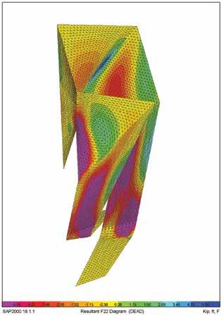

Stealth.
Structural Analysis
Work began by analyzing the structure with the finite element program SAP, using a mesh generated by Formations Studio and rectilinear shell elements of varying thicknesses to simulate the sculpture’s elliptical cross section. A centerline mesh was exported from the parametric modeling program Rhino and imported into SAP using the DXF format. The mesh was created by the artist using parameters specified by Uzun + Case. The varying thickness of the cross section was approximated by zones of constant thickness which stepped at their intersections with one another. The sharing of electronic information greatly expedited the analysis process. Both service and ultimate stresses/forces were considered. The service level results were based upon a 10-year return period and used to calculate crack widths and deflections. The ultimate level forces were based upon a 700-year return period and used for strength design. ASCE 7-10 ultimate wind speeds correspond to approximately a 7% probability of exceedance in 50 years (Annual Exceedance Probability = 0.00143; MRI = 700 years). A combination of wind and gravity forces controlled the design of the structure. Seismic forces were not critical. Reinforcement for crack control was calculated first, followed by an ultimate strength check. The analysis results indicated that the upper portion of the sculpture behaved like a shell with relatively low stresses, necessitating a maximum thickness of only 7 inches. It was reinforced with a mat of #5 reinforcing bars at 4-inch on center each way. The lower portion of the sculpture was controlled by bending, necessitating an increase in thickness to 14 inches. The high bending stresses are resisted by (2) #7 reinforcing bars at 4-inch on center vertically with #5 horizontal ties at 4-inch on center. The accurate bending of the vertical bars to fit within the exacting forms was a
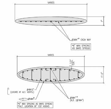
Upper portion cross section top. Lower portion cross section bottom. Leg to mat foundation connection detail.

Several options were considered for the design of the formwork system, including a solid system of ¾-inch plywood layers. Ultimately, to minimize material usage, a two-way structural rib system was chosen. It consisted of ¾-inch plywood ribs skinned with three layers of ¼-inch marine grade plywood, providing the flexibility to form the synclastic and anticlastic double curvatures required by the major challenge, which was executed in house by Formations Studio. sculpture.The digital modeling, indexing, and CNC routing of the The use of double #7s instead of #9 bars was based upon the studio’s formwork was a monumental effort given that each of the 183 pieces limited bar bending capabilities. of formwork for the sculpture was unique. Base supports consisted of four pinned nodes at each of the two legs. The rebar at the base was treated similarly with CNC cut templates The position of the supports corresponded to the centroid of vertical made for each bar to enable accurate bending. The bars and formwork reinforcing bar groups which connected the legs to the mat founda- for each section were transported to the site as a complete assembly. tion below. The mat foundation is 12 feet continued on next page x 15 feet x 16 inches thick, reinforced with #7@12 bottom and #6@12 top. The SAFE computer program was used to analyze and design this element based upon an allowable soil bearing pressure Design smarter of 2000 PSF. Crack control and durability were primary design parameters. The structure was ALL NEW GUIDE! Concrete design designed not to crack, except at the base aids on demand: where crack widths were limited to avoid durability concerns. Five (5) pounds per Guides cubic yard of Forta Ferro fibers were added to control cracking and improve durabilWebinars ity at thin cross sections. Cracking was eLearning evaluated using the computer program Response 2000 based on the reinforce- Online Tools ment and combined bending, axial, and shear forces at each section. Crack widths Technical Notes were limited to 0.2 mm in general but to avoid excessive thickness at the base of Reference Material the sculpture crack widths of 0.33 mm were allowed.
Formwork and Reinforcement Fabrication Visit www.crsi.org
Due to the complex and exacting nature of the structure, formwork and reinforcing steel fabrication was performed in the artist’s studio.
USE PROMO “STRUCTURE-2016” FOR 15% OFF YOUR PUBLICATION PURCHASE!
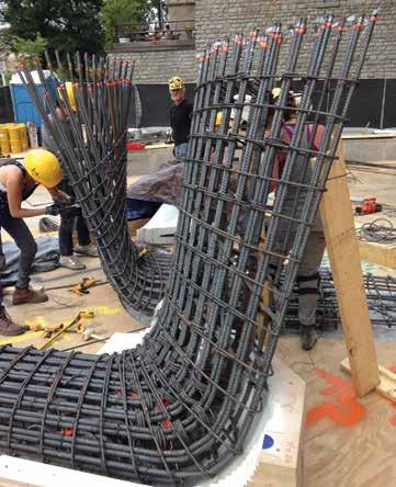
Base reinforcing.
Concrete Mixture
Initial studies for the structure considered steel fiber reinforced ultrahigh performance concrete. This proved impractical due to the high flexural stresses at the sculpture base and the need to create continuity at construction joints. A 5000 PSI conventionally reinforced concrete design was selected. The final mixture was developed with the assistance of Thomas Concrete Technical Services Laboratory. The mix design required 5000 psi and very high flowability to achieve the very thin profile details at the edge of the structure. Liquid integral color dosages were provided by Increte. Since aggregates make up such a significant portion of the mixture, and therefore greatly affected color, numerous lab batches were produced to look at local granite aggregates, imported black granites, and slags and finally the chosen material, a blue/black Georgia limestone. Seventy-six (76) ounce per cubic yard of SIKA ViscoCrete 2100 high range water reducer was used for dispersion, strength, and rheological properties.
Construction
To facilitate construction, an intricate scaffolding system was designed and built around the Sculpture, and erected in lifts as the formwork for the sculpture was placed. Form delivery was sequenced to avoid damage due to prolonged weather exposure. Formwork for the entire sculpture was left in place until concrete placement was complete. The levelness, elevation, and orientation of the foundation of the sculpture were critical. The foot and ankle placement was one of the most challenging due to the unusual geometry and the large amount of reinforcement. The structure was built in four-foot lifts, with forms that were bolted together. Due to the computer controlled manufacturing process, the formwork fit-up was excellent. The foot and ankle rebar was fabricated at the Formations Studio facility. All other reinforcement for the sculpture was bent on site. Much effort was made to ensure that the specified 1½-inch rebar clearances were maintained. Uzun + Case inspected all rebar before concrete placement. All concrete was placed via a line pump system. Concrete arrived with an integral color, Formwork. but a second color, ‘Carbon’, was added at the job site. Concrete spread averaged 24 inches. All concrete was vibrated for proper consolidation using a small head and motor assembly. Form removal was tedious due to the curvature of the sculpture. Finally, Formations Studio painstakingly shaped and polished the surface to achieve the glass-like finish. The sculpture was shaped with a steel cup wheel and wet polished using a diamond pad system utilizing increasing fineness from 50 grit to 3000 grit. Finally, the structure was coated with a lithium polysilicate penetrating densifier/ sealer (Pentra-Sil by Convergent Concrete Technologies).
Structural Monitoring and Performance
To verify structural modeling assumptions, Uzun + Case instrumented the finished sculpture with accelerometers to measure its fundamental frequency. The measured value of 2.5 hz was within 5% of the value predicted by the eigenvalue analysis when adjusted for average actual vs. specified concrete strengths. This gave added confidence that the complex computer model had accurately captured the behavior of the structure. The finished surface was inspected and observed to be of excellent quality and free of visible cracks other than those at the ankle zones, which are of predicted width. It was satisfying to have predicted the cracking performance accurately, but the author was secretly hoping for the cracks not to appear! This demonstrates the importance of managing expectations in advance since all parties were satisfied with the resulting performance.
Collaboration
Artist and engineer, working together, were able to create a concrete structure of extraordinary geometric complexity, thinness, and grace. Stealth was the result of a collaborative and respectful working relationship between artist and engineer. The artist thought like an engineer in conceiving of a form that was not only interesting and beautiful but also structurally feasible and buildable. The engineer thought like an artist in striving to make the structure not only stable but also as thin and as faithful to the artist’s vision as possible.▪
Jim Case, P.E., is a Senior Principal at Uzun + Case, LLC in Atlanta, GA. He can be reached at jcase@uzuncase.com.


TORNADO SHELTERS IN SCHOOLS
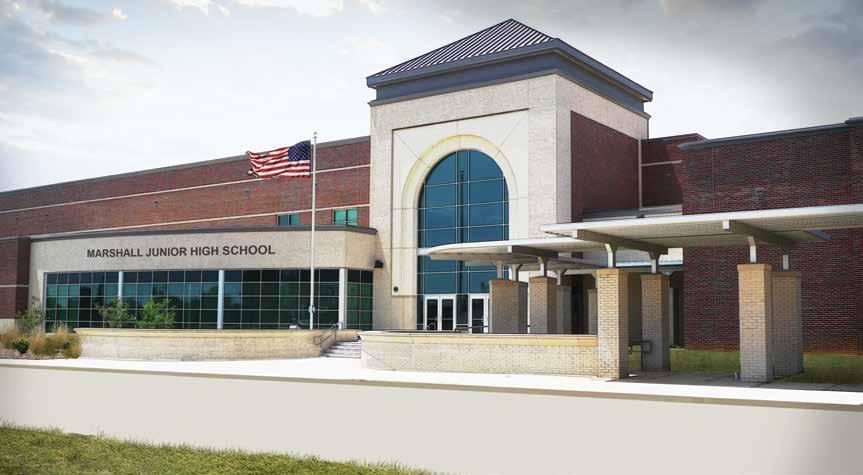
Masonry Tornado Shelter Case Study: Marshall Junior High, Marshall, TX
By Benchmark H. Harris, P.E., S.E., LEED AP
Th e new Junior High School for Marshall Independent School District in Marshall, Texas.
Section 423 of the 2015 International Building Code (IBC) has a new requirement that construction for new schools and additions to existing schools (up through high school, with some limited exceptions) have tornado shelters. Th ese shelters must comply with ICC 500-2014 ICC/NSSA Standard for the Design and Construction of Storm Shelters if the project is located in the zone where the minimum required design wind speed for a tornado shelter is 250 mph, as shown by the shaded region in the attached map. (Th is requirement for tornado shelters also applies to critical emergency operations such as fi re, rescue and 911 call centers.) Many of the structural engineering requirements involve coordination with a Local Emergency Planning Committee, the school district, architect, civil engineer, mechanical engineer, electrical engineer, technology designer and even the interior designer. Furthermore, ICC 500-2014 requires independent peer reviewers for both structural and architectural provisions, as well as an onsite structural engineer hired by the Owner to make observations during construction as part of the quality assurance plan. All this coordination elevates the signifi cance of the primary structural engineer’s role during the planning of the shelter, and can require a greater eff ort than for traditional structures. When Huckabee (an Architectural and Engineering fi rm) began master planning construction with Marshall Independent School District (MISD) in Marshall, Texas, they informed the district of the new IBC requirements. While the current building code in Marshall does not require tornado shelters yet, new construction will be required to have tornado shelters after the city of Marshall adopts the 2015 IBC. MISD elected to proactively have tornado shelters designed in all of the four new facilities associated with a recent bond program. Th e current building code in Marshall is the 2009 IBC, which only requires tornado shelters be designed using ICC 500-2008 if a part of a building is specifi cally designated as a tornado shelter. Th erefore, these shelters were designed using the 2008 version (the fi rst edition) of the ICC 500 standard. It is important to note that there are some signifi cant diff erences between the 2008 and 2014 versions of the ICC 500 standard. Both versions require standardized debris impact testing (2x4 missiles). Section 803.1 of the older version requires that doors, windows and impact-protective systems be tested at the “maximum size” listed for use. However, the new version requires these systems be tested at both the “maximum and minimum size” listed for use. Th e general rationale for the new, additional requirement is that smaller components can theoretically be more rigid. Th is rigidity means less time for energy transfer and that can equate to greater forces on parts of the system. Having specimens created and tested by a laboratory takes time and money; therefore, many component manufacturers have tested only one large size for each model and not tested small specimens yet, primarily because they have not had time to react to the new provision for minimum size testing in ICC 500-2014. Th e eff ect is that many building components need to be the same size as tested if the ICC 500-2014 standard is used, and those sizes are generally larger than is preferable for daily use of the facility. For example, ASSA/ABLOY makes a StormPro door system that would have to have 4 foot wide x 8 foot high doors rather than the smaller, standard sizes for doors. Th e new Marshall Junior High is under construction currently and is designed to have 121,560 square feet of fl oor plan area. Th e Marshall ISD Local Emergency Planning Committee indicated that the number of occupants required for design of the shelter is 1,400 people, which was based on Texas Education Agency requirements and the actual anticipated population (rather than what the IBC would require for fi re egress, which would be much higher); and, the City of Marshall agreed with this interpretation. ICC 500 requires at least fi ve square feet of open fl oor plan area for each occupant, with ten square feet for occupants in wheelchairs. Th erefore, the design team recommended using the portion of the facility generally intended for locker rooms which had suffi cient open area (including a long corridor), a low roof elevation (approximately 15 feet above fi nish fl oor), and concrete masonry construction for durability and low maintenance cost in the locker room environment. continued on next page
ICC 500 requires that “lay down, rollover and collapse hazards” be considered. Because the locker room area is adjacent to a series of taller practice gymnasiums, additional loads were simulated by adding the weight per square foot of wall area for the gymnasium wall system to the weight per square foot of roof area for the gymnasium roof, and multiplying that sum by 1.5 to simulate impact as with crane loads. Designers applied this additional live load pressure over a horizontal distance from the perimeter of the shelter against the gymnasium, equal in horizontal length to the difference in elevation between the top of the gymnasium parapet to the mean roof height of the shelter. This was to simulate the gymnasium wall forming a hinge at the top of the shelter and a hinge at the roof-to-wall connection for the gymnasium, with the mechanism collapsing on top of the shelter. This method was approved by the Local Emergency Planning Committee and the district’s Independent Structural Engineering Peer Reviewer. The Tornado Shelter for the Marshall Junior High project was designed with load-bearing, reinforced concrete masonry walls with a composite steel beam and concrete slab over metal deck structural roof system. The wind pressure governed the design of the wall over the debris impact resistance criteria. The walls generally consist of fully grouted 12-inch CMU with two vertical #5 reinforcing bars (double curtain) at 16 inches on center and various patterns of horizontal reinforcement. Debris impact testing reported by Texas Tech University demonstrated that the specified masonry assembly is acceptable. Proper grouting is essential for quality masonry in tornado shelters. If voids form behind the face shells as grout shrinks, it is possible that debris impacts on the exterior face of the wall could cause the face shells on the interior face to delaminate and become projectiles within the shelter. Instead of having a mechanical ventilation system which would require back-up power for two hours, such as an emergency generator that would need to be protected from wind pressures and debris impact, a method of providing natural ventilation was specified. Atmospheric Pressure Change (APC) venting was not provided due to the adverse impact the large openings would have on the use of the space; a value of GCp = +/-0.55 was used under the exception that does not require APC venting. Providing a means for natural ventilation when the shelter is activated, but closing off this system when the building is under normal occupancy, presents numerous architectural, mechanical, electrical, and structural challenges. There are requirements for lower openings and upper openings for air circulation. Because masonry is constructed in-place by trained craftsmen, baffling chambers, such as the one shown, that have various partitions to divert the trajectories of possible debris impact (which can be much smaller than the standardized 2x4 missile) were easy to design, specify and have constructed. (Other systems, such as precast concrete, are more limited in their ability to provide customized baffling systems that work with typical architectural floor plans.) Tall parapets are not desirable because flying debris like trees can catch on them; therefore, a 2-foot maximum parapet height from top of the CMU to top of the concrete roof deck was designed. The 2-foot maximum parapet criteria provided sufficient height for detailing flashing and allowing roof slopes with a constant height top-of-wall architectural elevation. Because the location was not at the front of the building, the short parapet height was aesthetically acceptable. Baffling (to divert debris and thus slow down impact) is required for any openings in the shelter envelope greater than 3.5 square inches; therefore, roof drains were avoided by having the roof drain off of the low wall without a parapet. ICC 500 requires a quality assurance plan, addressed for this project by embedding provisions in the quality control specifications for the entire project. For the entire project, the specifications require that
Debris impact baffling chamber for natural ventilation.
an Independent Quality Control Agency (IQCA) perform or provide all special inspection, special testing, and structural engineering observation for the shelter according to the “Statement of Special Inspections, Testing and Observation” in Specification Section 01 4533 titled Code-Required Quality Control. The qualifications for the structural observer are that the individual be a Professional Engineer (PE) licensed in Texas and listed on the Texas Board of Professional Engineers as practicing structural engineering or be a Structural Engineer (SE) licensed in Texas. The on-site masonry inspector is required to be a certified TMS Masonry Field Testing Technician. The masonry testing technicians are required to be certified TMS Masonry Laboratory Testing Technicians.
Summary
The 2015 International Building Code has a new requirement that tornado shelters be designed in all new school construction (up through high school) in over a quarter of the United States. The MISD Junior High project is an example of how ICC 500 (which was not originally written to be a mandatory requirement for schools) was applied to provide school occupants protection from tornados. Reinforced masonry was selected for its compatibility with the use of the space, considering its durability and flexibility to meet structural and performance criteria.▪ Benchmark H. Harris, P.E., S.E., LEED AP, is the Director of Engineering for Huckabee, an Architecture & Engineering firm with six offices all over Texas. He is the Chair of the The Masonry Society (TMS) Disaster Investigation Program and the recipient of the 2015 Paul Haller Award from TMS. He is currently working with the ICC 500-2014 Committee on the development of a Commentary document. Mr. Harris can be reached at bharris@huckabee-inc.com.


Performance-Based Design of 111 Main in Salt Lake City
By Mark Sarkisian, S.E., Peter Lee, S.E., Alvin Tsui, S.E. and Lachezar Handzhiyski, S.E.
111 Main’s reinforced concrete core wall system provides vertical and lateral support for an innovative 25-story office tower suspended over adjacent performing arts center.
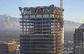
Courtesy of City Creek Reserve, Inc.
Located in a region of high seismicity in close proximity to the active Salt Lake Segment of the Wasatch Fault Zone, the new 111 Main office tower in Salt Lake City, Utah, comprises 501,455 square feet of Class A office space. The 25-story building rises 387 feet above grade and contains a penthouse roof-level steel hat-truss system with all perimeter columns suspended to allow for air-rights overhang at adjacent performing arts center. The overall project design challenges and solutions were described in STRUCTURE magazine, June 2016. This article focuses on the two stage performance-based seismic design methods undertaken by the design team during the project design development, independent peer review, and approval process. Designed to meet the minimum requirements of the 2012 International Building Code (IBC) and ASCE 7-10 provisions, the building superstructure construction incorporates a ductile reinforced concrete core wall system that exceeds the height limit of 160 feet per ASCE 7-10 Table 12.2.1. Thus, as a non-prescriptive alternate design method permitted by IBC Section 104.11, performance-based seismic design procedures were adopted following the guidelines of the Pacific Earthquake Engineering Research Center (PEER) Tall Building Initiative Guidelines (2010). The PEER TBI guidelines require that code equivalent or better performance is demonstrated at peak Maximum Considered Earthquake (MCER, 2% in 50yr, 2475 ARP) demands. Under construction, 111 Main is scheduled to be completed in August 2016.
Two Stage Performance-Based Design
In addition to the ambitious design challenge of hanging all 18 perimeter steel columns from penthouse roof trusses to allow an airrights overhang at the new 4-story performing arts center directly to the south of the tower, the project was driven by a fast-paced design and construction schedule to achieve project deadlines and commitments. During the Stage 1 procedure, final proportioning of reinforced concrete core wall design including thicknesses, openings, boundary zones, and link beams was achieved using simplified tri-directional linear response spectrum analysis and design. During the Stage 2 procedure, which included rigorous oversight by the Seismic Design Review Panel (SDRP), the team conducted tri-directional nonlinear response history analysis (NLRHA) to demonstrate that the structure design, determined in Stage 1, satisfied the performance-based inelastic design criteria of the PEER TBI guidelines. Site-Specific Response Spectra and Ground Motions Site-specific response spectra and ground motions for the Maximum Considered Earthquake (MCER) were developed per ASCE 7-10 requirements by the geotechnical engineer, URS, and the SDRP. The MCER spectrum was defined as the lesser of the deterministic and probabilistic MCER ground motions. To address the response of the hat-truss supported structure, vertical spectra was developed based on the median V/H ratios of Gϋlerce and Abrahamson, defining two sets

of conditioned horizontal and vertical response spectra. For the Stage 2 NLRHA procedure, two suites of seven sets of three-component ground motion time histories, spectrally scaled to the MCER spectra, were selected. Each of the seven ground motions were randomly rotated as recommended by SDRP. Structural Systems Description The superstructure typical framed levels consist of WF steel composite deck and slab construction with perimeter W14 columns as shown in Figure 1. The ductile reinforced concrete shear wall core construction includes 30-inch-thick walls extending from the top of the basementlevel pile-cap foundations to the underside of the trussed penthouse at Level 25. The core walls are configured on two grid lines in the east-west direction (62 feet 6 inches) and three grid lines in a northsouth direction (42 feet 9 inches) utilizing specified self-consolidating concrete with a strength of 8,000 psi except at Level 24, below the hat-trusses, where 10,000 psi is needed. Perimeter column loads representing approximately 40% of the building gravity dead and live loads are transferred from the roof hat-trusses to the top of the core walls via six articulated spherical structural steel bearings. The core wall loads are transferred to a deep foundation system consisting of driven steel HP-piles extending to depths of 100 feet and greater below grade, with a total of 373 HP14 piles.
Stage 1: 3D Linear Analysis and Design
The design team was challenged to use linear dynamic modal response spectrum analysis (MRSA) during a 10-week design development phase to finalize the proportions, design, and quantities of the ductile reinforced concrete bearing wall system. These details were needed prior to building a 3D-nonlinear analysis model to demonstrate compliance with the performance-based design PEER TBI MCER level acceptance criteria. The two-stage strategy included a Stage 1 linear MRSA and a Stage 2 nonlinear analysis verification of the Stage 1 results which would occur during the final construction document design phase. A 3-dimensional ETABS by Computers and Structures, Inc. (CSI, v2013) linear analysis model was developed for the MRSA with 5% modal damping. The structure seismic force resisting system (SFRS) was modeled and included the complete gravity and lateral structural system load path from foundations (pinned at basement level), basement walls, Level 1 diaphragm, core walls, hat-trusses, floor framing, hanging perimeter columns, and structural bearings at top of core walls below Level 25 trusses. Stiffness property modifiers were used as recommended in PEER/ATC 72-1 (2010) for the concrete lateral and gravity elements to account for cracked section
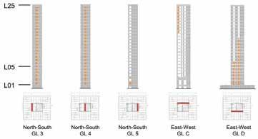
Table 1. Stiffness property modifiers used in Stage 1.
Element EI GA
Basement Wall 0.20 0.12 Core Shear Wall 0.50 1.00 Link Beam 0.15 1.00 Level 1 Diaphragm 0.20 0.12 Tower Diaphragm 0.50 0.50
Table 2. R-Factors at MCER level used in Stage 1.
Element Rx and Ry
Rz
Link Beam 3.5 1.0 Flexural in Shear Wall 3.5 1.0 Shear in Shear Wall 2.0 1.0 Steel Roof Truss 2.0 1.0 Steel Hanging Column 2.0 1.0 Foundation System 2.5 1.0
Table 3. Expected material properties (φ=1.0).
Material
Reinforcing Steel in Concrete
Concrete
ASTM A992/A572 Steel
Expected Strength
1.17 fy
1.3 f' c
1.1 Fy
properties during a seismic event as summarized in Table 1 with additional conservative assumptions made for the shear stiffness of core wall and link beam elements, as well as the lower bound stiffness for the ground level diaphragm. To estimate demands at MCER level using Stage 1 MRSA, more conservative values of ductility based system response modification R-factors were utilized for the bearing wall system than prescribed by code minimum (ASCE 7-10) requirements (R=5 at DE, 2/3 MCER). These values, as summarized in Table 2, were based on recent research summarized in NEES webinar, Performance, Analysis and Design of Flexural Concrete Walls by Lehman and Lowes (2013). The research included a 1/3 scale testing program with wall specimens detailed with varying parameters per ACI 318-11 requirements, correlated with FEMA P695 probability based collapse prediction modeling. The research concluded that R-factors for various high rise concrete wall systems to achieve 20% probability of failure at MCER was about 3.5, which is significantly lower than the ASCE 7-10 value and the shear demand in core wall should be increased by a flexural overstrength factor and dynamic amplification factor. A simplified approach was utilized for 111 Main using R=3.5 for deformation controlled actions and R=2 for force controlled actions. At MCER level demands, expected material properties and capacity reduction factor, φ=1.0, were assumed as summarized in Table 3. Since IBC 2012 and ASCE 7-10 do not explicitly address the directional combinations for vertical seismic load, the ASCE 4-98 (2000) Section 3.2-26 standard for the Seismic Analysis of Safety-Related Nuclear Structures was referenced for defining the combined horizontal and vertical seismic load combinations. Combining with PEER TBI
(2010) Section 7.6.1, the tri-directional seismic load combinations used in Stage 1 analysis at MCER MRSA were as follows, where Lexp is the expected live load (25% of the unreduced live load): 1) 1.0D + Lexp ± 1.0Ex ± 0.4Ey ± 0.4Ez 2) 1.0D + Lexp ± 0.4Ex ± 1.0Ey ± 0.4Ez 3) 1.0D + Lexp ± 0.4Ex ± 0.4Ey ± 1.0Ez Following coordination of core wall openings with the Architecture/MEP design team, and preliminary analyses indicating high wall and link beam shear stress concentrations, the structural design team introduced additional new and modified core wall openings to reduce stress concentrations at story stiffness and strength transitions as shown in Figure 2. The additional link beams introduced by these openings significantly increased the ductility of the structure while balancing the stiffness along parallel core wall grid lines.
Stage 2: 3D Nonlinear Analysis and Design
Therefore, the structure remains essentially elastic and satisfies the service-level immediate occupancy performance objective. Stage 2 Nonlinear Analysis Modeling The 3-D nonlinear analysis model using PERFORM-3D (CSI, v2011) is shown in Figure 3. The model included the core walls, all hanger columns and hat truss elements comprising the SFRS and load path in resisting both horizontal, and vertical seismic loads. At typical steel framing levels, masses were lumped at perimeter columns and core wall locations, with rigid diaphragms at Levels 2 to 24. The model was pinned at a basement foundation level with no soil support springs modeled at basement walls. Concrete core walls were modeled using the PERFORM-3D Inelastic Shear Wall element using two vertical steel and concrete fibers per panel zone element and four fibers per each boundary zone element. Coupling beams were modeled using five different models, depending on reinforcement arrangement and aspect ratio, utilizing With the development and design of the SFRS deter- both conventional and diagonally reinforced beams. mined from Stage 1 linear elastic procedures, a Stage Model material properties were based on most recent 2 nonlinear analysis procedure was used to evalu- recommended research and testing results. ate the design using the PEER TBI procedures and acceptance criteria during the project construction Performance Studies document phase. Establishing the project specific Some significant performance studies were conducted procedures and criteria included the collaborative rec- in assessing the structure and model before commencommendations of the SDRP in the final verification, design, and detailing of the structure. The SDRP input included additional performance checks consistent Figure 3. PERFORM-3D (CSI) nonlinear analysis model. ing with the NLRHA to address questions posed by the SDRP. These studies included hat-truss gravity load effects on the concrete core ductility and strength, with the intent of the PEER TBI guidelines. The guidelines provide an cracking vs. yield moment core capacity, displacement-based design alternative to the prescriptive procedures for seismic design in ASCE 7 concepts assessing the distribution of vertical reinforcement ratio, and with the intent to permit the design of buildings using non-prescriptive coupling beam strength vs. core flexural strength checks over the height systems of equivalent performance that are capable of achieving the of the core wall structure. Figure 4 illustrates nonlinear core wall behavior seismic performance objectives of Occupancy Category II buildings. using a core cross section fiber model (XTRACT) in consideration of The guidelines consider the inelastic response of the structure’s global global axial-moment and moment-curvature effects demonstrating a behavior and element components using NLRHA at the MCER level substantial increase in moment strength due to additional compressive collapse prevention performance objective. The 111 Main acceptance loads from the hat-truss. Cracking vs. yield moment capacity at upper criteria included consideration of bounded basement level backstay effects, levels with low flexural reinforcement ratio was also considered. inter-story and residual drift limits, as well as consideration of force and deformation controlled element component performance in the SFRS at the MCER. Serviceability at the 43-year earthquake event was also Stage 1 & Stage 2 Summary Results considered, but spectral demands were significantly less than those from Representative summary analysis results show good correlation in the MCE spectrum reduced by the Stage 1 response modification factors. comparison of Stage 1 (MRSA) and Stage 2 (NLRHA) procedures.
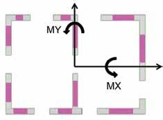
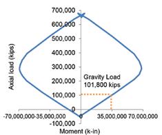
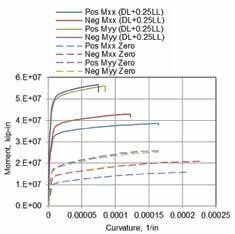
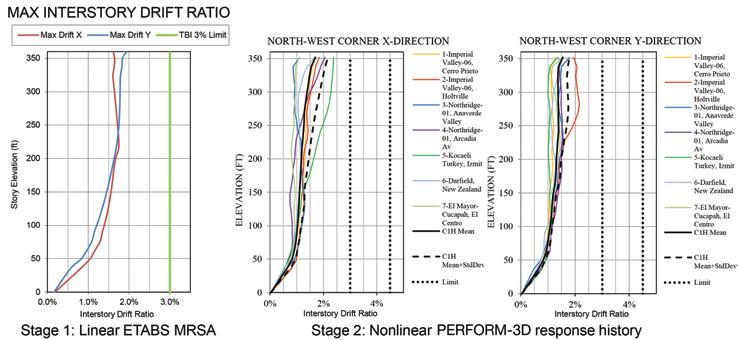
Figure 5. Summary Stage 1 & Stage 2 interstory drift demands.
While predicted MCER inelastic inter-story drift ratio demands (Figure 5) are similar, the nonlinear analysis of Stage 2 illustrates a more uniform redistribution of peak pier wall shear stresses. These global summaries, as well as additional Stage 2 results including limits on wall strains at confined and unconfined concrete, coupling beam rotations and residual drift demands, demonstrate full conformance with the project design criteria and with the performance intent of ASCE 7-10 for Occupancy Category II buildings. two-stage methodology allowed for early coordination of the seismic force-resisting system with architecture and MEP design teams without compromising the quality of structural solution delivered in the final design. The simplified Stage 1 approach can be used in concept and schematic design of tall core wall buildings in high seismic regions to assess design feasibility quickly without the need for complex nonlinear analysis. The reader is referred to a more detailed summary of this twostage performance-based design approach in SEAOC 2015 Convention paper, by the authors, titled, Performance-Based Design of 111 Main. ▪
Conclusions
Faced with an accelerated design and construction project schedule, the SOM structural design team developed a two-stage performancebased methodology which required close collaboration with the SDRP to achieve performance objectives and meet project milestone deadlines. While utilizing a simplified Stage 1 linear MRSA procedure, the
Acknowledgments
The authors gratefully acknowledge the 111 Main project sponsors led by City Creek Reserve, Inc. and Hamilton Partners for their strong support of the design team in reaching project goals and objectives. We thank the Seismic Design Review Panel led by Chair Chris Kimball, Joe Maffei, Karl Telleen and Norm Abrahamson for their constructive recommendations and collaboration. In Salt Lake City, Eric Kankainen served as structural plan reviewer. Bill Gordon was project geotechnical engineer with seismic hazards developed by Ivan Wong and Patricia Thomas at URS. We also thank Phil Miller and the team at Dunn & Associates for their valuable support in the development of the analysis and design of the deep foundation system.
Mark Sarkisian, S.E., (mark. sarkisian@som.com) is Partner, Peter Lee, S.E. (peter.lee@som.com) is Associate Director, Alvin Tsui, S.E., (alvin.tsui@som.com) is Associate, and Lachezar V. Handzhiyski, P.E., (lachezar.handzhiyski@som.com) is Design Engineer, Skidmore, Owings & Merrill LLP in San Francisco, CA.