5 minute read
Spotlight


The formation process for windward roof step drifts is more complex than that for leeward drifts because of the presence of a separated flow region and an eddy or trapped vortex upwind of the step that initially drives snow out of that region. The initial drift shape is non-right triangular, as shown in Figure 3. For 3-D obstructions such as poles or posts, the eddy is termed a horseshoe vortex because of its plan shape. The trapped vortex initially prevents snow accumulation in this region and leads to the peak drift initially being about one step height upwind of the step. During this initial phase of windward drift formation (Phase I), the wind-transported snow layer, e.g., the saltating snow particles, are within the wind streamlines that notionally enter the upwind separated region. As such, nearly all of the snow particles stay upwind of the wall, and hence, the trapping efficiency becomes nominally 100%. If strong winds persist (wind speeds greater than about 10 mph), the windward drift upwind of the step continues to grow, forming a snow ramp that effectively “fills in” the upwind separation region. This process weakens the trapped vortex and eventually eliminates it. Then the saltating snow particles join the wind streamlines flowing over the step. At this point, the 100% trapping efficiency phase (Phase I) ends, the trapped vortex at the step begins to fill with snow, and the trapping efficiency drops to approximately 20% (80% of the saltating snow particles flow over the step). During this next phase, the windward drift’s shape morphs from its initial non-right triangular shape (Phase I) to a right triangular shape (Phase II), with the peak drift depth being at the step. If strong winds continue and the snow source remains un-depleted, the Phase II windward drift becomes aerodynamically streamlined when the drift reaches the top of the wall and the slope is about 1 on 8.At this point, the geometric irregularity has been removed and additional drift formation ceases.
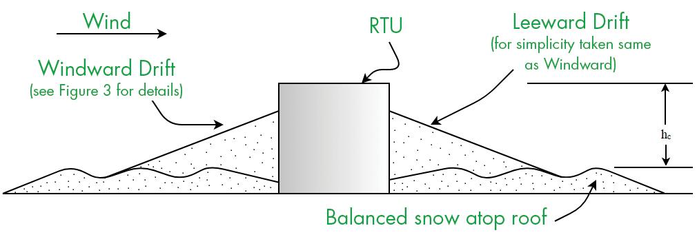
Parapet Wall and Roof Projection Drifts By their nature, the snowdrifts at parapet walls and upwind of roof-top units (RTUs) are windward drifts. For RTUs, drifts also form simultaneously at the downwind side, as shown in Figure 4. However, for simplicity, ASCE 7 specifies the upwind side windward drift for that location as well. Recently, ASCE 7 has addressed the issue of mitigation of snow drifting at RTUs. In particular, if the RTU is raised 2 feet above the balanced snow, this vertical gap is assumed to prevent drift formation at the RTU. This provision is advantageous if a smaller RTU on an existing roof is replaced by a new, larger, and heavier RTU.
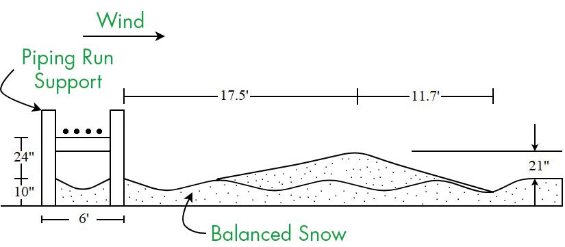
Figure 4. Snowdrift at a non-elevated Roof Top Unit (RTU). Wind from left to right. Unexpected Drift The authors became aware of an unusual roof-top snowdrift during a recent forensic investigation in the Midwest. As shown in Figure 5, the snowdrift formed downwind of a run of roof-top cooling pipes. Somewhat surprisingly, the total load, in pounds per foot (lbs./ft.), for the piping-run drift was comparable to that for a leeward roof step drift with the same upwind fetch and design ground snow load. There were several reasons why the drift was both unusual and unexpected. First of all, the drift was centered about 17 feet downwind of the downwind edge of the piping-run. Hence, unlike the well-known leeward roof step and gable roof drifts described above, the downwind piping-run drift was well removed from the geometric irregularity (i.e., the piping run itself). This contrasts with the common leeward drifts described above, which form adjacent to the geometric irregularity. Furthermore, the vertical gap between the bottom of the pipes (pipe diameter nominally 6 to 12 inches) and the top of the balanced snow surface was about 2 feet. This seems to contradict the recent ASCE 7 provisions for elevating RTUs to avoid windward and leeward drift formation. It should be mentioned that, as part of the forensic investigation, it seems that one structural engineer involved with refrigerated storage facilities design had observed similar roof-top piping drifts in the past. A 2003 report by Ronald Tabler, Controlling Blowing and Drifting Snow, prepared for the National Cooperative Highway Research Program for the Transportation Research Board of the National Academies, presents photographs of drifts downwind of box beam and W beam roadside guard rails. Hence, the snowdrift shown in Figure 5 is not an aberration. At first, the authors thought the piping-run drift to be an anomaly. However, over time, a plausible explanation for the drift’s “unusual” aspects developed. One would initially anticipate that snow drifting around roof-top piping would behave similarly to drifting around RTUs. Both provide an obstruction to roof-top wind flow. However, since the piping’s crosswind extent is much larger than an RTU, the piping is nominally a 2-D obstruction rather than a typical RTU, which would be considered a 3-D obstruction. Wind flow over the top and around the sides of a typical RTU results in two aerodynamic shadow regions – one immediately upwind and the other immediately downwind where drift formation occurs. A downwind region of reduced wind speed – a wake region – exists at an RTU, but the downwind extent of the wake region behind the piping-run extends further downwind than that of the RTU. As opposed to forming an adjacent aerodynamic shadow, piping-run drifts form well downstream of the obstruction due to the reduced speed and increased turbulence in the wake. In relation to the drift mitigation gap for a raised RTU, the wind flows beneath the unit as well as over the top and around the sides. The gap and resulting flow below an elevated RTU eliminates the aerodynamic shadow regions and hence eliminates drift formation on both the upwind and downwind sides Figure 5. Observed piping-run drift. Wind from left to right. of the RTU. Artic buildings are often placed on stilts for this