46 minute read
Structural Components
structural COMPONENTS Tackling the 3-Sided Box Diaphragm: One Engineer’s Perspective
By Jim Lintz, P.E., S.E., LEED AP BD+C
Many engineers consider rectangular structures with light gauge metal deck diaphragms unstable if they are laterally supported on only three sides. Given the standard assumption that light gauge metal deck diaphragms are completely flexible, this type of structure, often referred to as a 3-sided box, would be unstable. While this assumption is often useful for diaphragm design, it is not strictly true. Light gauge metal deck diaphragms have stiffness, and 3-sided box structures are stable when designed properly. A design method for this type of diaphragm was introduced in the Steel Deck Institute’s Diaphragm Design Manual (DDM) 2nd Edition in 1995. Since then, many single-story structures have been designed using this method, demonstrating its validity. Additional information can be found in the current DDM 4th Edition in Section 10, Example 7.
It is not uncommon for tilt-up and precast warehouses in low seismic regions (SDC A & B) to be designed with a rectangular diaphragm laterally supported on three sides when an expansion is added to an existing building or when an expansion joint is required due to the building length. The following explanation and design example focuses on wind loads on a rectangular building with shear walls on three sides and no lateral force resisting system (LFRS) on the fourth. The fourth side is assumed covered, with no wind pressure acting on it.
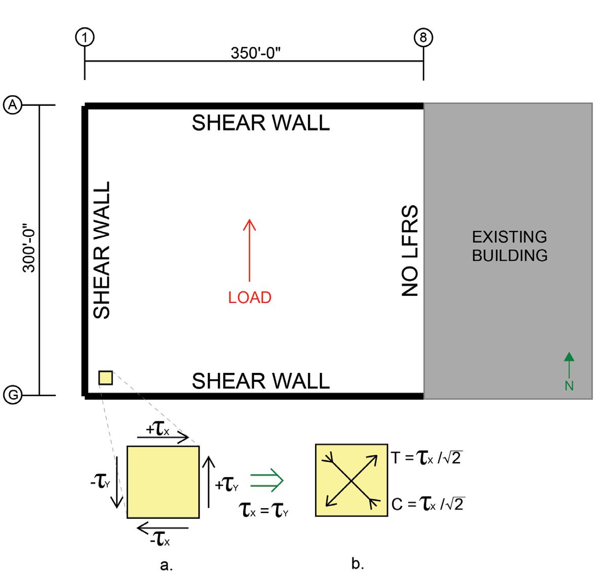
Figure 1. 3-sided box diaphragm with a) traditional unit shear diagram and b) alternate unit shear diagram with diagonal tension/compression struts.
Windward/Leeward Shear Loads
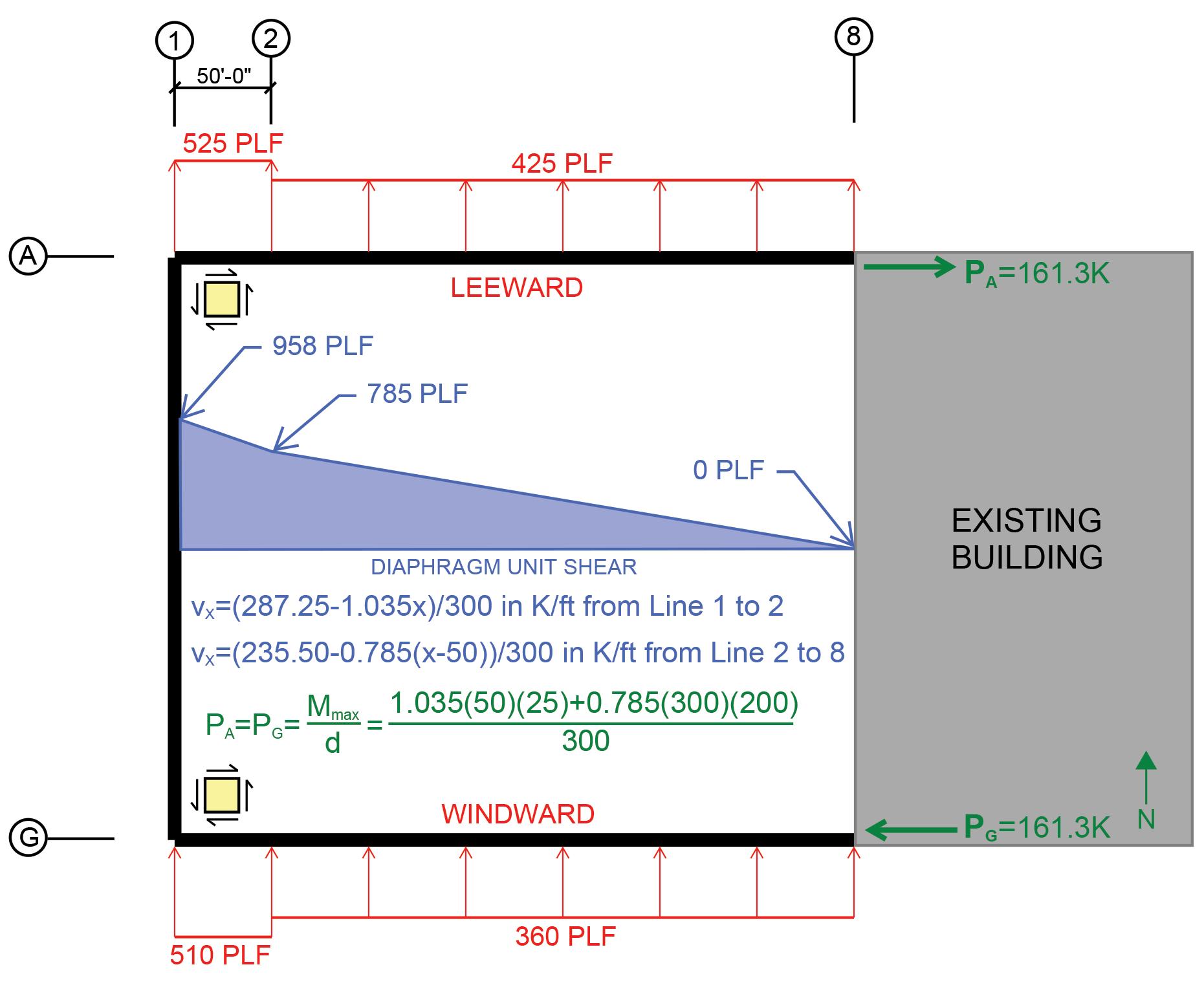
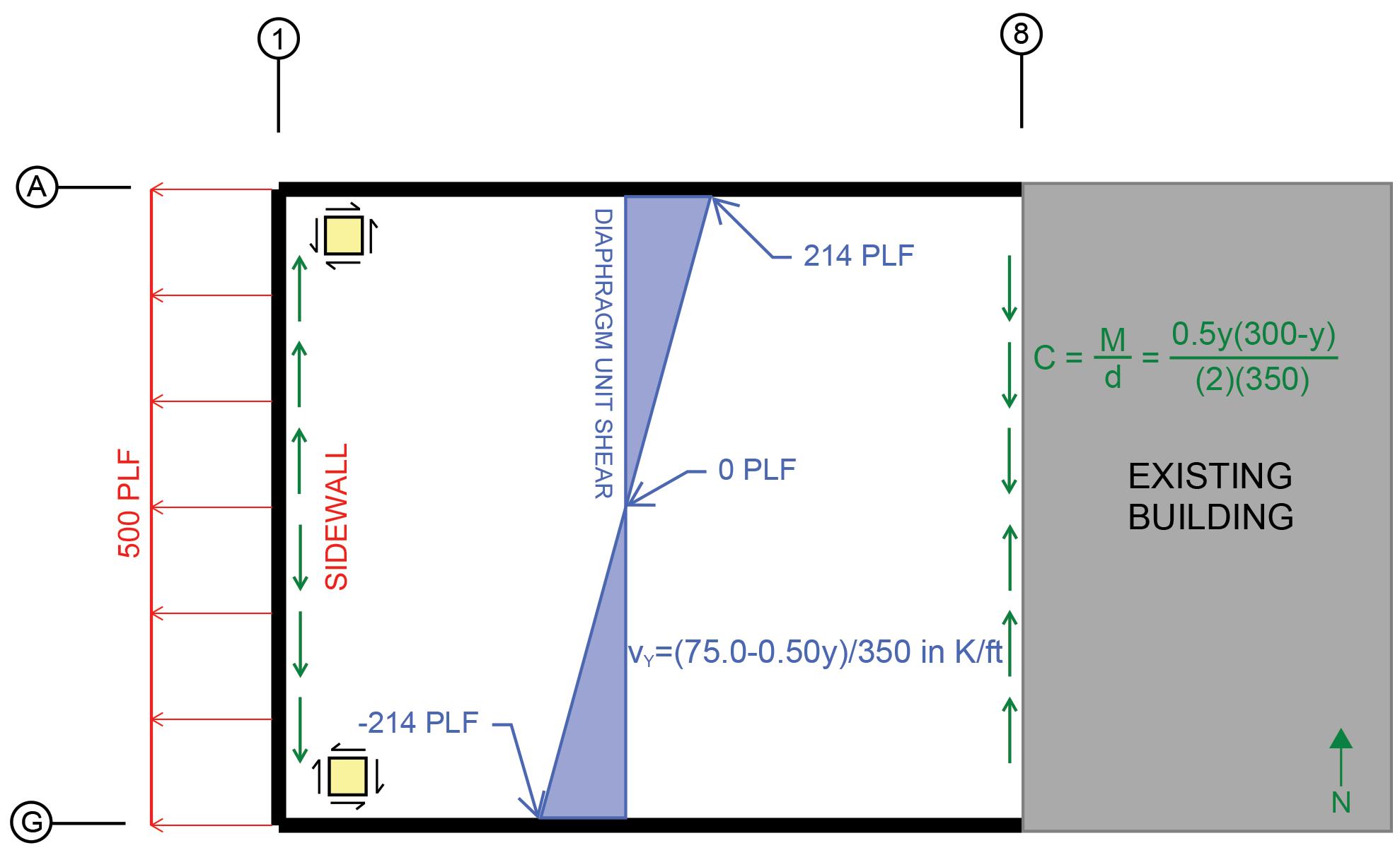
For lateral loads in the north/south direction (Figure 1), parallel to only one shear wall, the shear and moment in the roof can be calculated as if the roof were a fixed-free beam, fixed at the shear wall end and free at the opposite end. The shear wall parallel to the load resists the shear in the north/south direction, while the shear walls perpendicular to the load act as flanges to resist the moment. The LFRS’s perpendicular-to-the-wind load must form a couple to resist the moment to keep the structure in equilibrium and resist twisting and structural collapse. In addition, these shear walls must transmit the lateral load from the roof diaphragm to the foundation to complete the load path and stabilize the structure. Inherent in this design approach is that the roof behaves as a rigid diaphragm. ASCE 7-16 Section 26.2 permits untopped steel decks to be idealized as rigid for wind design if the span-to-depth ratio is not greater than 2. Yet, Section 12.3 only allows concretefilled metal deck to be idealized as rigid for seismic design, forcing semi-rigid analysis of the deck. However, relative stiffnesses of the diaphragm and vertical lateral force resisting systems do not affect the total load distribution to any of the vertical LFRS. With restraints on only three sides, the only way for the system to maintain equilibrium is for the loads to be distributed as if it were a standard rigid diaphragm. The shear diagram produced by this loading in the north/south direction is intuitive based on standard beam theory. Figure 2 shows the unit shear diagram for the loads given in the figure. The total load that must be resisted by the shear walls perpendicular-to-thewind load, to maintain equilibrium and resist the torsion on the structure, can be calculated by ensuring the sum of the moments on the structure equals zero. This can be done easily if the point about which the moments are calculated is chosen as corner A-1 or G-1. The total load P in shear walls A and G can be calculated by dividing the moment at A-1 or G-1 by the depth of the roof. Figure 2 shows the calculation of this force where the load, P, at lines A and G must be in opposite directions to maintain equilibrium. For the load, P, to accumulate in shear walls A and G, the load must be transferred from the diaphragm into the shear walls. It is often assumed that this is an additional shear load in the diaphragm that needs to be combined with the direct shear parallel with the wind load. However, this is not correct. The shear being
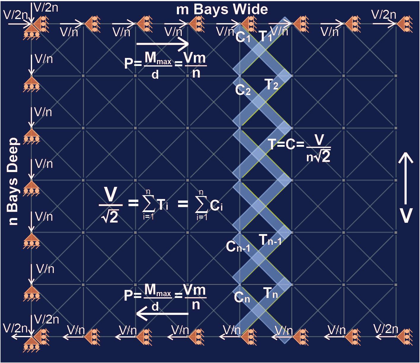
transferred into the shear walls at lines A and G is the perpendicular component of the direct shear and is not additive. To better understand this, consider the shear on a small square section of the roof diaphragm, as shown in Figure 1a. For equilibrium to be maintained on this roof section, for both translation and rotation, a force couple must exist on both the left and right and top and bottom of the square. In Figure 1a, the component of the shear stress parallel with the load is represented as τy, and the component of the shear stress perpendicular to the load is represented as τx. It is the τx shear stress that is transferred into the shear walls at A and G. Admittedly, considering small square sections of a diaphragm with stress couples and transforming that into the loads on a large roof is not intuitive. As evidence that the load transferred to shear walls A and G is a component of the direct shear and not additive, consider the following. First, take into account that the area under the shear diagram in Figure 2 equals P. Second, consider that the unit load transferred into shear walls A and G can be calculated by taking the change in moment in the diaphragm between two adjacent points and dividing that by the depth of the building (δM/δx)/d and that this will exactly equal the shear diagram in Figure 2. Shear as Tension/Compression Struts It may also be helpful to consider the shear in the diaphragm from another perspective. Shear, considered a set of perpendicular tension and compression stresses turned 45 degrees from the applied load, as shown in Figure 1b, is equivalent to Figure 1a. Each resists the same amount of shear, and each has equilibrium maintained. ere are, however, two advantages of viewing the shear as shown in Figure 1b. Generally, it provides a clear illustration of why shear cracks in concrete form at 45 degrees to the applied load. Specifi cally, this case provides an easier way to visualize how shear can be transferred into a shear wall perpendicular to the applied load. If the diagonal tension and compression loads are enlarged from the small square of the roof diaphragm into macro-level x-braces throughout the roof, it provides an alternative method for viewing the roof shear, as illustrated in Figure 3 (page 24). By setting up a model of the example building’s roof diaphragm with an x-brace in each bay, roller supports around the perimeter resisting translation parallel to the shear walls, and a shear load, V, at the free end, statics can be used to show how the shear load is transferred into the shear walls. With n bays vertically and m bays horizontally, it also allows a quick calculation for the load, P, in shear walls A and G. Since the load in each diagonal member is V/(n√2), the horizontal component is V/2n. ere are 2m diagonal members framing into each east/west shear
Figure 2. Example 3-sided box structure with 50-foot square bays and windward/leeward loads. wall; therefore, the total load P = 2Vm/2n = Vm/n, which equals the moment at corners A-1 or G-1 divided by the roof depth as discussed above. Readers are encouraged to spend 15-20 minutes setting up a similar diaphragm in their preferred structural modeling software with various loading patterns. e results will demonstrate the structure’s stability, the shear in the diaphragm, and the load transfer to the shear walls. Sidewall Shear Loads While the windward and leeward wind loads being transferred to shear walls A and G are not additive to the direct shear, there is often additional shear load in this type of 3-sided box structure that BUILD YOUR CAREER AT KL&A We are currently looking for: • Structural Engineers • Civil Engineers • BIM Technicians • Construction Managers ADVERTISEMENT–For Advertiser Information, visit GOLDEN | LOVELAND | C ARBONDALE • Steel Detailer Please visit klaa.com/open-careers for more information and to apply. | BUFFALO STRUCTUREmag.org
does need to be considered. When calculating the Main Wind Force Resisting System forces in the diaphragm of a traditional 4-sided structure, the sidewall wind forces often cancel each other out since they are equal in magnitude but act in opposite directions. However, for the 3-sided box shown in this example with no wall at line 8, there is no opposing sidewall wind force to counteract the sidewall wind at line 1. is sidewall wind pressure produces a shear diagram like a simply supported beam between the two parallel shear walls, as shown in Figure 4.
Combining Shear Loads
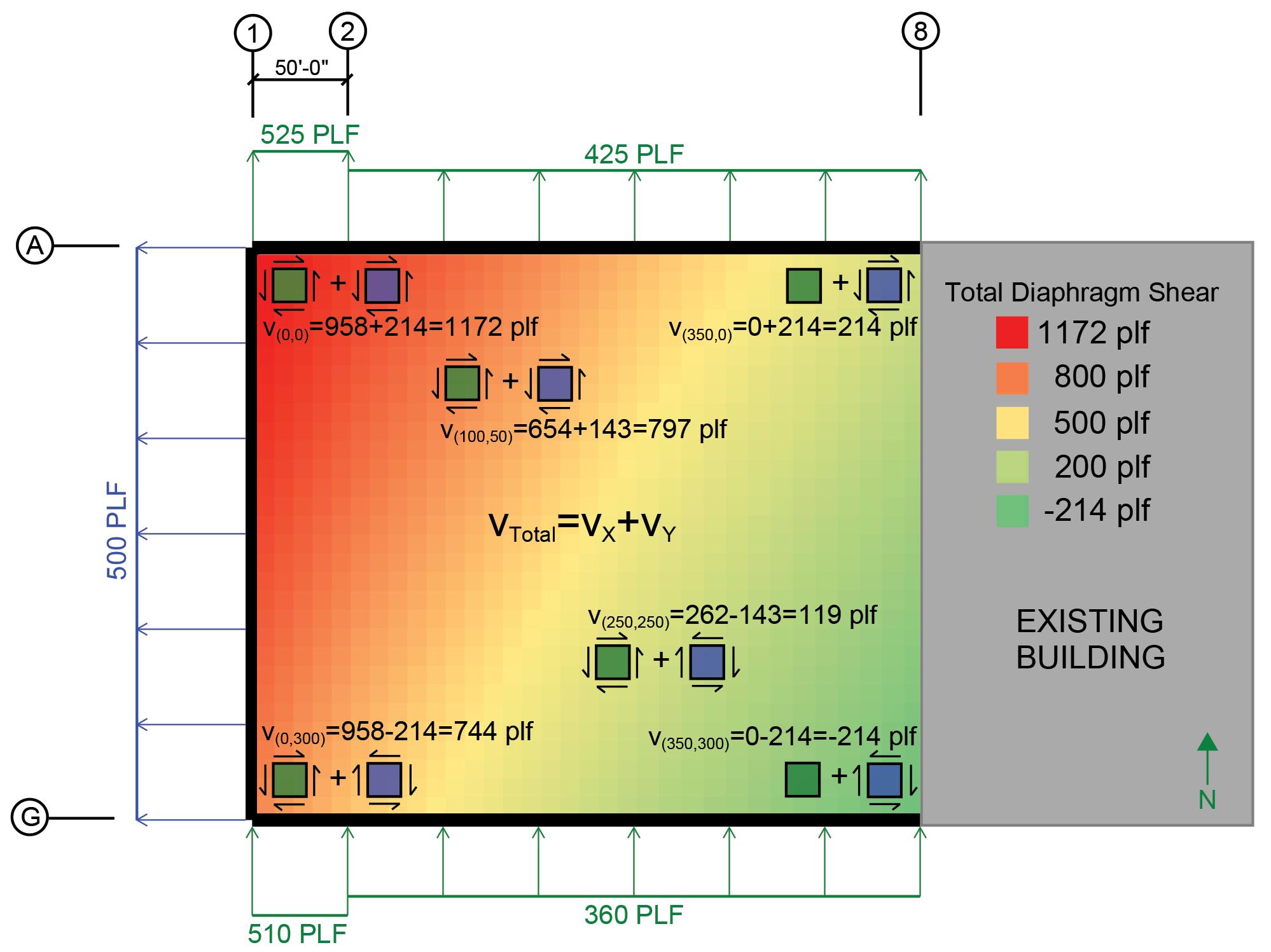
e sidewall wind shear must be added to the windward and leeward wall wind shear to calculate the total shear load in the diaphragm at any location. At Line A, the combination of the shear loads is additive, while at line G, the shear loads are in opposing directions. e shear diagrams on small squares of deck shown in Figure 5 can help visualize the shear direction at various locations. e maximum shear occurs at corner A-1 and decreases when moving away from the corner in each direction. is combined shear load is checked against the diaphragm shear capacity to determine the adequacy of the design. e wind may blow in any direction, so while corner A-1 may have the maximum shear one moment, corner G-1 may have the maximum shear the next. e diaphragm should be designed
Figure 3. Tension/Compression strut diaphragm model. with this in mind. On large diaphragms, it is common to vary the deck gauge and connection patterns across the roof as the shear forces change.
WSECU PLAZA
SEATTLE, WA
AIA Seattle Honor Award
Excellence in Masonry Award
Seattle Tacoma Lacey Portland Eugene Sacramento San Francisco Los Angeles Long Beach Orange County San Diego Boise Salt Lake City Des Moines St. Louis Chicago Louisville Nashville Birmingham Washington, DC New York
KPFF is an Equal Opportunity Employer. www.kpff.com

TOGETHER WE BUILD SOLUTIONS
Photo Courtesy of Nicholas Worley
Chord Forces
e sidewall wind pressure creates bending moment in the roof. is moment can be calculated by assuming the roof as a simply supported beam between shear walls. At the free end of the structure, this moment is generally designed to be resisted only by the members along line 8. e sidewall pressure-producing suction on the wall creates a compression chord force at line 8, which can be calculated as shown in Figure 4. is force will typically either be resisted by the top chords of the joists along line 8 or by a continuous perimeter angle. If resisted by joist top chords, a tie plate or tie angles must be added between joists to transfer load from one joist to the next. e tension force created by the moment in the diaphragm at line 1 will not build up in the perimeter angle along the wall as the compression force does in the perimeter angle/ joist top chords at line 8. At line 1, the chord force is transferred into the wall panels at each connection. Similarly, the chord force along lines A and G from the windward/leeward loads will
not build up in the perimeter angle along those lines but will be transferred to the shear walls with each connection.
Design Considerations
While the ANSI/AWC wood code (Special Design Provisions for Wind and Seismic, SDPWS) places dimensional limits and L/W ratio limits on diaphragms of open-front structures, there are no such dimensional or L/W ratio code requirements on light gauge steel roof deck diaphragms. As a practical matter, it is generally advisable to limit the unit shear in the deck to that which 20-gauge deck can resist. Experience has shown that adding a line of braces or moment frames near the open end of the structure is generally less expensive than leaving that end without an LFRS when 18-gauge deck is required due to the cost of the heavier deck and additional deck connections. To ensure that all lateral deflection requirements are met, the deflection of the diaphragm must also be checked. As noted in the DDM 4th Edition, a diaphragm with the dimensions shown in this example is controlled by shear deflection; therefore, flexural deflection is ignored. Assuming uniform stress over the depth of the diaphragm,
Figure 4. Example 3-sided box structure with sidewall wind loads. the deflection between any two points can be calculated by the following integration: ∫ x x 2 1 V bG' dx, where V is the shear, b is the depth of the diaphragm, and G´ is the diaphragm shear stiffness. For a uniformly loaded cantilevered diaphragm with a uniform depth and uniform stiffness, the maximum deflection at the free end can be calculated as ∆= qL2 2bG' , where q is the uniform load and L is the length of the diaphragm. For this example, where the load is not uniform across the entire length of the diaphragm, the deflection at the free end can be found by dividing the area under the unit shear curve shown in Figure 2 by G´. The equation for G´ can be found in the DDM 4th Edition and varies based on the deck type and gage, fastener type, and connection pattern. Rectangular light gauge metal roof deck diaphragms with LFRS on three sides have been successfully designed and constructed using the design method described above for decades. Efficient and safe designs can be implemented with a proper understanding of the shear in the roof diaphragm and how it is transferred to the shear walls. Understanding this design approach provides engineers with another arrow in their quiver of design techniques and provides another way to meet client needs.■
Figure 5. Example 3-sided box structure total unit shear loads in diaphragm. Jim Lintz is a Structural Engineer at LJB Inc. in Dayton, OH (jlintz@ljbinc.com).
Restoring a Century-Old Building
By Lauren Feinstein, P.E., Jordan Weinstein, P.E., and Kevin Poulin, Ph.D., P.E.
The newly renovated NH Collection New York Madison Avenue Hotel, located at 22 East 38th Street in Midtown Manhattan, is housed in the former Renaissance Revival-style Fraternities Club Building constructed in 1923. The seventeenstory building is approximately 125 feet wide by 100 feet long by 220 feet tall and has multiple setback roofs. The NH Hotel Group, SA (NH) hired Simpson Gumpertz & Heger, Inc. (SGH) as the Engineer of Record, and HLW International, LLP (HLW) as the Architect of Record, to modernize and transform the hotel. The work included creating two double-height lobbies, updating the facilities, and modernizing the guest rooms. These upgrades required strengthening and repairing the existing structure. NH engaged Newgrange Construction (Newgrange) as the contractor for the renovation.
Without the benefit of design drawings from the original construction, SGH investigated and documented the existing building structure – a transitional masonry superstructure (a historic hybrid system comprised of a steel skeleton embedded in the exterior brick masonry walls) with draped-mesh, cinderconcrete floor slabs. Since the hotel remained open during the investigation phase, surveying the existing conditions could not disturb the guests or affect the architectural finishes. As a first step, Langan Engineering, Environmental, Surveying, Landscape Architecture, and Geology, DPC (Langan) was retained to survey the columns and perimeter masonry walls, and SGH performed localized ground-penetrating-radar (GPR) surveys to locate existing steel beams. SGH also used a comparative-loading analysis, where possible, to eliminate the need for additional probes and subsequent analysis of the structure. SGH strategically documented probes at a limited number of back-of-house locations to obtain representative steel column sizes and beam sizes for analysis. They targeted areas critical to the design and planned to verify the remaining structure during construction.
As the contractor removed interior finishes during construction, SGH discovered the undocumented structural history of the building and encountered a series of unforeseen conditions. For example, despite assumptions about uniform floor plans, the beam layouts varied substantially throughout the building, leading the project team to address an unexpected scope of strengthening and repair, in addition to several redesigns, during construction.

The inherent stability of Atlas Tube’s Jumbo HSS helps architects realize extraordinary plans, including the beautiful peak of One Vanderbilt in New York City.


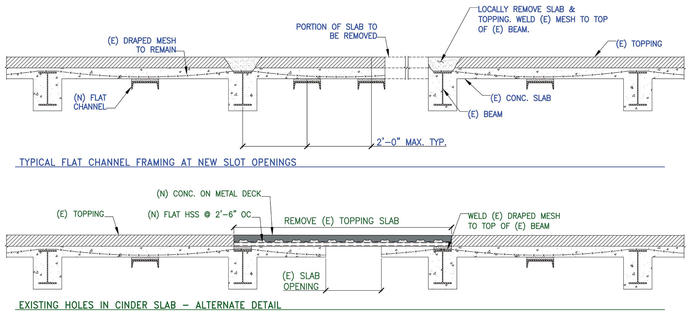
Figure 1. Draped-mesh cinder-concrete slab strengthening details at floor penetrations
The original structural scope of work for the transformation consisted of redirecting lateral loads around two new double-height lobbies, designing an interior steel-framed glass vestibule, and adding rooftop dunnage to support a new generator, screen wall, and mechanical units. The scope of work also consisted of framing slotted slab openings at new MEP penetrations at all floors and infilling existing double-height spaces with new steel framing and concrete-on-metal-deck slabs to increase the usable floor space. SGH considered several issues for new openings in the drapedmesh cinder-concrete floor slab. The existing floor system typically consisted of a 3-inch-thick non-structural cinder fill with a 1-inch cement topping slab over a 4-inch-thick structural cinder-concrete slab with draped, steel-wire mesh that spanned one-way between encased steel beams. The draped steel mesh supports the slabs via catenary action. The 1968 New York City Building Code (NYCBC) governs modifications to archaic structural systems used on this project and specifically addresses openings and penetrations in this type of floor system. According to the 1968 NYCBC, a single opening greater than 18 inches or multiple openings totaling over 18 inches in any 10-foot width or span of slab must be framed. As the creation of new floor openings comprised a large portion of the structural scope, SGH proposed two options (topside and underside) for slab strengthening (Figure 1). Both details satisfied the architect’s strict head-height criteria and avoided increasing the floor load enough to trigger additional beam strengthening. The cinder fill was removed locally and replaced with a thin slab on deck that spanned to shallow HSS beams for the topside repair option. This system bypassed the existing slab and was supported entirely on the existing steel floor framing. For the underside repair option, the existing slab spanned as plain concrete between flat channels tight to the underside of the slab spaced at 2 feet on-center. Additionally, the 1968 NYCBC quantifies that when the mesh is continuous over steel beams at both ends (i.e., middle spans), the slab has approximately 40% more capacity than an equally reinforced end span. For new openings exceeding the above threshold for opening size, SGH reanalyzed cinder-concrete slabs in bays adjacent to the bay of the opening, as end spans due to the discontinuity in the mesh, and designed strengthening, as required. For strengthening adjacent bays, SGH designed a flat channel at the midspan of the bay. While SGH initially intended to use these details for new floor openings, the details were also applicable when the contractor discovered numerous, closely spaced large floor openings from prior renovations that required
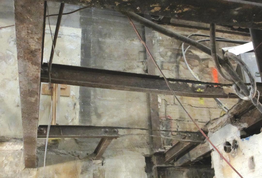
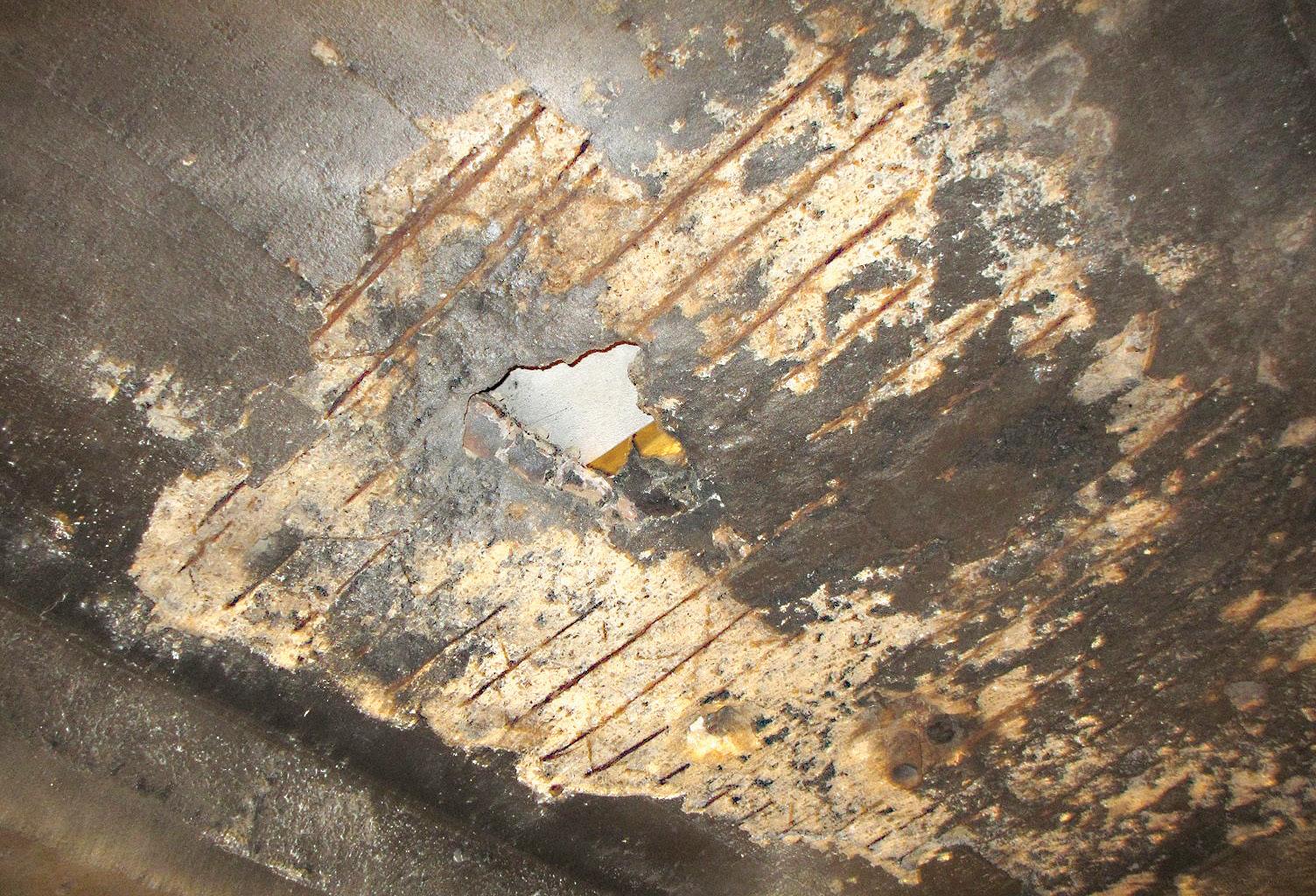
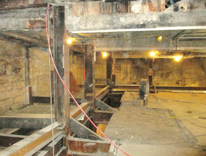
Figure 3. Cellar column temporary bracing.
support. This unforeseen condition accounted for approximately half of the floor strengthening. Another unforeseen condition, concealed by ceiling finishes, was extensive corrosion and deterioration in the cellar floor. Maintenance staff informed the project team that steam pipes leaked for decades in the cellar and subcellar. This triggered a thorough investigation of the cellar structure to assess its condition. As shown in Figure 2a, some of the steel beams had nearly complete section loss. As shown in Figure 2b, all that remained of the wire mesh in deteriorated sections of the slab was rust staining on the concrete. After the contractor installed temporary shoring, SGH visually surveyed the underside of the cellar slab, looking for spalled or cracked concrete, and requested that the contractor sound these areas to locate additional delamination within the slab. SGH also identified steel beams with cracked concrete encasements that indicated expansive pressure from corrosion. SGH directed the contractor to remove the encasements and grind the corrosion to bare metal at these beams. SGH then measured and documented the remaining cross-sections and determined whether strengthening was necessary. This survey led to the removal and replacement of approximately half of the cellar slab and framing, in addition to some local strengthening of corroded steel columns. Seven perimeter columns relied on the deteriorated portion of the cellar floor structure for bracing. For temporary bracing prior to slab removal, SGH designed a new grid of horizontal, inclined, and skewed steel braces, just above the existing cellar floor (Figure 3), which connected the affected columns to the remaining floor diaphragm, avoiding obstacles such as slab steps and floor openings. In addition, SGH designed replacement beams and slabs and worked closely with the contractor to sequence piecewise beam and slab demolition and replacement to ensure that the existing columns were continually braced during reconstruction. As part of the architectural transformation, HLW designed two large floor openings, the larger of which was 55 feet long by 35 feet wide in the second-floor slab, to create a spacious double-height lobby for the hotel (Figure 4). Several floor beams needed to be removed to create this space, resulting in seven columns becoming unbraced in one or both directions. SGH designed plate reinforcing for these columns to strengthen them for their newly doubled unbraced lengths. SGH sequenced the installation of
the strengthening plates to avoid temporary shoring of the columns; the contractor locally cut the flanges of the existing beams at the connections to the columns and installed slotted strengthening plates around the beam webs. The contractor demolished the slab and floor beams only after installing all column strengthening. In addition to strengthening the columns, SGH redirected the lateral loads around the new large openings in the second-floor diaphragm. The original lateral-load-resisting system consisted of semi-rigid moment connections and masonry shear walls. SGH designed WTs to be installed below the existing slabs to redirect the lateral loads around the openings and back to a continuous line of columns. At the exterior of the building, where the demolition for the double-height space would disconnect columns from the diaphragm, SGH retrofitted the existing connections to create a new moment frame to resist the redirected lateral loads. At this moment frame, SGH designed single-sided channel strengthening for the existing double-height columns as the exterior faces of the columns were not accessible. The demolished second-floor framing had supported a large, cantilevered marquee over the entryway. SGH strengthened the existing spandrel supporting the marquee with a welded plate between the existing spandrel flanges, creating a closed section that could resist torsion loads from the cantilevered marquee. As this beam was also part of the new moment frame, SGH designed its connections to the columns to resist the torsion loads, in addition to transferring the moments. This renovation preserved the beauty of the Fraternities Club Building’s early years, boasting its restored ornamental brick-andsandstone facade, Romanesque arches, red tile roofs, and copper-clad octagonal cupolas. At the completion of the structural upgrades and interior overhaul, The NH Collection New York Madison Avenue Hotel opened to guests in May 2021. The upscale hotel features 288 new guest rooms, an onsite gym, a bar, and two spacious lobbies.■ All authors are with Simpson Gumpertz & Heger, Inc. Lauren Feinstein is a Consulting Engineer (lpfeinstein@sgh.com). Jordan Weinstein is a Consulting Engineer (jcweinstein@sgh.com). Kevin Poulin is a Principal (kcpoulin@sgh.com). Figure 4. New spacious double-height lobby.

Nashville International Airport’s Inspirational Terminal Lobby and IAF Expansion Project Rise to Meet Soaring Passenger Demands

By Terry Palmer, P.E., Tom Meyer, P.E., S.E., and Kevin Kuntz, P.E., S.E.
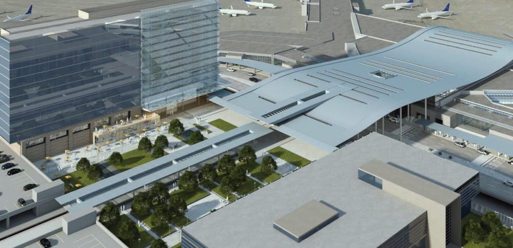
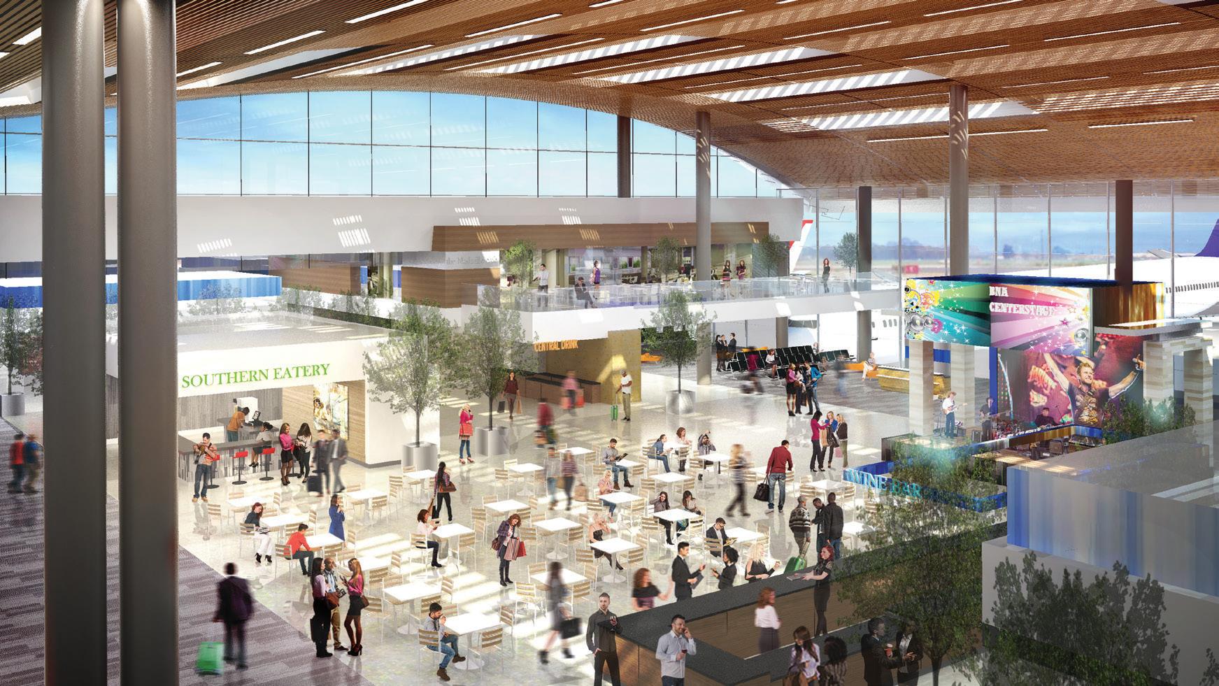
Concept rendering of the curvilinear roof and entry at Nashville International Airport. Courtesy of Corgan.
So much of Nashville, Tennessee, is defi ned by the inspired and creative music of the famed Music City. So when the airlines approached Nashville International Airport® (or BNA, as it is also known) with requests to expand their facilities to meet ever-increasing numbers of domestic and international passengers, it was clear the project would need to embody its city’s energy and character.
It was a tall order. Overall, the BNA Vision includes a new Terminal Lobby and International Arrivals Facility (IAF), parking garages, an airport hotel, expanded Concourse D, and a central utility plant. e plans also called for more gates, ticket counters, and spaces for dining and shopping experiences to better serve passengers and airport personnel. At its centerpiece: a curvilinear “airwave” roof canopy that would inspire and awe.
Moreover, the airport had to remain open, safe, and inviting to passengers throughout construction; the project scope and schedule were daunting; and the BNA Vision, when completed, would so thoroughly revamp the airport that visitors would be hard-pressed to fi nd any signs of the old terminal. Yet competition soared when the Metropolitan Nashville Airport Authority (MNAA) shared early renderings and videos of the BNA Terminal Lobby and IAF Expansion project’s design. It seemed that nearly everyone in the airport design and construction industry wanted to design and build the new terminal.
A Design that Captures the Spirit of Flight
With multiple projects planned at once, MNAA needed a unifying experience so each project would work well with the overall campus texture and architecture. As such, Joel Efrussy and Ross Payton, Senior Associate and Principal, respectively, at Corgan led a series of stakeholder workshops and community outreach meetings, which revealed wonderful insights regarding the features and design themes that should be captured and refl ected – including Cumberland Forest’s natural beauty, Music City’s unique culture, and Nashville’s diverse and vibrant people and neighborhoods. Many of these elements are expressed in the Terminal Lobby’s iconic and conspicuous airwave roof canopy, which draws in cascading natural light and visually connects the pedestrian bridge entry to the airfi eld. “Corgan brought a number of canopy styles and options, but we felt the curvilinear form best represented the spirit of fl ight,” explained Robert Ramsey, BNA’s Senior Vice President and Chief Operating Offi cer. e roof canopy’s initial structural design was well-thoughtout and included in the bridging documents off ered to prospective design/build teams. e initial structural concept developed by Rao Patri, Principal at the structural
design firm of Logan Patri in Nashville, was supported on several existing building columns to keep the roof lightweight. The concept also employed a new, braced-frame, lateral design in lieu of the existing moment-frame structure of the original terminal. To transform the airwave canopy roof concept renderings into an actual structural design, Magnusson Klemencic Associates (MKA) collaborated with Hensel Phelps and Fentress Architects during the RFQ phase to generate creative ideas that would add value, reduce costs, and shorten construction schedules. Early images of the new BNA Terminal Lobby motivated the design/build team to figure out how they could make an already excellent design concept even better. • As a bonus, the existing roof could temporarily serve as a work platform for crews to install ducts and pipes within the new roof without requiring construction lifts, resulting in faster and safer installation. • Finally, raising the roof enhanced views and allowed natural light to cascade into the terminal, reminiscent of sunshine filtering through the Cumberland Forest trees.
“Most importantly, modifying the airwave canopy structural concept allowed for a much more elegant design that truly resulted in a form that was inspired and driven by function,” added Corey Ochsner, an Associate Principal and Project Manager at Fentress Architects. “By removing almost all of the interior columns, we were able to capture amazing views and spatial openness.”
Amazing Views and Spatial Openness
Meeting with Neal Terrell and Scott Shelby, Project Development Director and Operations Manager, respectively, at Hensel Phelps to prepare to respond to the Request For Qualifications (RFQ), Terry Palmer, Senior Principal at MKA, floated the idea of raising the new canopy roof a few feet from where the concept roof was envisioned. Upon sketching this idea, the team discovered some amazing design revelations: • The existing terminal roof could stay in place until the new roof was built and weather tight, thus avoiding huge issues with weather protection within the existing terminal throughout construction. • By providing a clear-span roof structure over the existing terminal and roadway, the project team could avoid strengthening the roadway and terminal structure entirely, thereby saving time and money. More importantly, this would allow the airport to remain open and operational throughout construction. • The project team could eliminate all the proposed braced frames and interior columns within the existing terminal building, thereby achieving tremendous openness and unobstructed views.
The Terminal Lobby’s iconic airwave roof canopy draws in cascading natural light and openness. Courtesy of Corgan. The “Bones” of Innovative Design To better understand what gives the airwave roof canopy its singular and iconic form, it is important to look at the structure’s “bones” – particularly its trusses and column placements. As the project team studied the roof geometry, it was evident that the conceptual design form was created with true radial arcs and The new terminal roof was lifted a few feet to span over the existing occupied terminal and roadway – offering tremendous structural, architectural, and construction benefits.

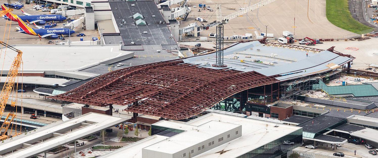
At Nashville International Airport, the new roof’s unique, mildly rippled form is created with just two curvilinear spine trusses. Courtesy of Aerial Innovations Southeast.
tangents to ease fabrication. As the structural design advanced, a decision was made to minimize, as much as possible, the number of curved members to reduce fabrication costs. Amazingly, the roof’s unique, mildly rippled form is created with just two curvilinear “spine trusses” that carry the entire roof. In a true collaboration, MKA, Fentress Architects, Corgan, and MNAA worked together to slightly adjust the roof’s profile to accommodate deeper spine trusses and sharpen the roof’s edges to achieve a knifeedge, wing-tip aesthetic. To achieve schedule goals and cost savings, the project team utilized straight, secondary trusses to frame between the two spine trusses, resulting in a roof profile that softly curves. Further, the roof trusses were preassembled at the fabrication plant, shipped to the site, and erected with minimal field assembly. The project team avoided weaving braced frames down and through the Terminal Building, with visual openness being so vital. Instead, the canopy roof and IAF addition are interconnected as a single, homogeneous, 660-foot-long structure with a maximum span of 180 feet and stabilized by a moment-frame lateral system. By avoiding joints in the roof, stability during steel erection was far easier to achieve. Moreover, the potential for leaky building joints was eliminated. Meanwhile, column placement was very surgical. The canopy roof’s support columns and moment frames, located on the landside over the roadway and new Parking Plaza, had to be installed several months ahead of the canopy roof itself. Working closely with Brad Miller, Callie Hepler, and Don Shoop at Hensel Phelps, the team identified two “sweet spots” where cruciform columns could be placed directly through the roof of the existing terminal without hitting the huge glass façade, and with just enough room to continue operating the rental car counters in the lower level. Similarly, MKA and Hensel Phelps collaborated with Messer Construction’s Parking Plaza team to identify where columns could be placed within their new elevator towers just days before foundations were built. To accommodate this column placement, two plate girders spanning 100 feet were utilized to maintain the continuity of the spine trusses. The plate girders were built using Grade 65 plates and were tapered – ten feet, three inches deep at the peak, and eight feet deep at the ends – to mimic the profile of the straight secondary trusses. The canopy roof itself was erected in three discrete phases, which were closely coordinated with the fabricator and the erector so that roofing, skylights, clerestory glazing, piping, and other elements could be installed early to shorten the overall construction schedule. In addition, as mentioned, the subcontractors took full advantage of the existing roof, using it as a work platform to install ducts and pipes without erecting scaffolding or employing lifts.
BNA: A Great Story of Collaboration
What began as a need to expand and improve the Nashville International Airport evolved into a tremendous story of many dedicated people working closely together and united by the desire to contribute and make the BNA Vision even better than hoped. In a sense, what began as a passion for building something extraordinary in Nashville has turned into a great story of collaboration. Like a co-written song, the talents and abilities of many people contributed to a vision that will resonate for many years to come. Most visitors will not know the “hows and the whys” of the airport’s design and construction, but they will definitely know they are in Nashville, Tennessee!■
All authors are with Magnusson Klemencic Associates. Terry Palmer is a Senior Principal (tpalmer@mka.com). Tom Meyer is a Principal (tmeyer@mka.com). Kevin Kuntz is a Senior Design Engineer (kkuntz@mka.com).
Project Team
Master Architect – BNA Vision: Corgan Lead Structural Design: Magnusson Klemencic Associates Design/Build Lead: Hensel Phelps Architect of Record: Fentress Architect Associate Architect: TM Partners Substructure Design: Logan Patri Mechanical/Electrical Design: IC Thomasson Associates
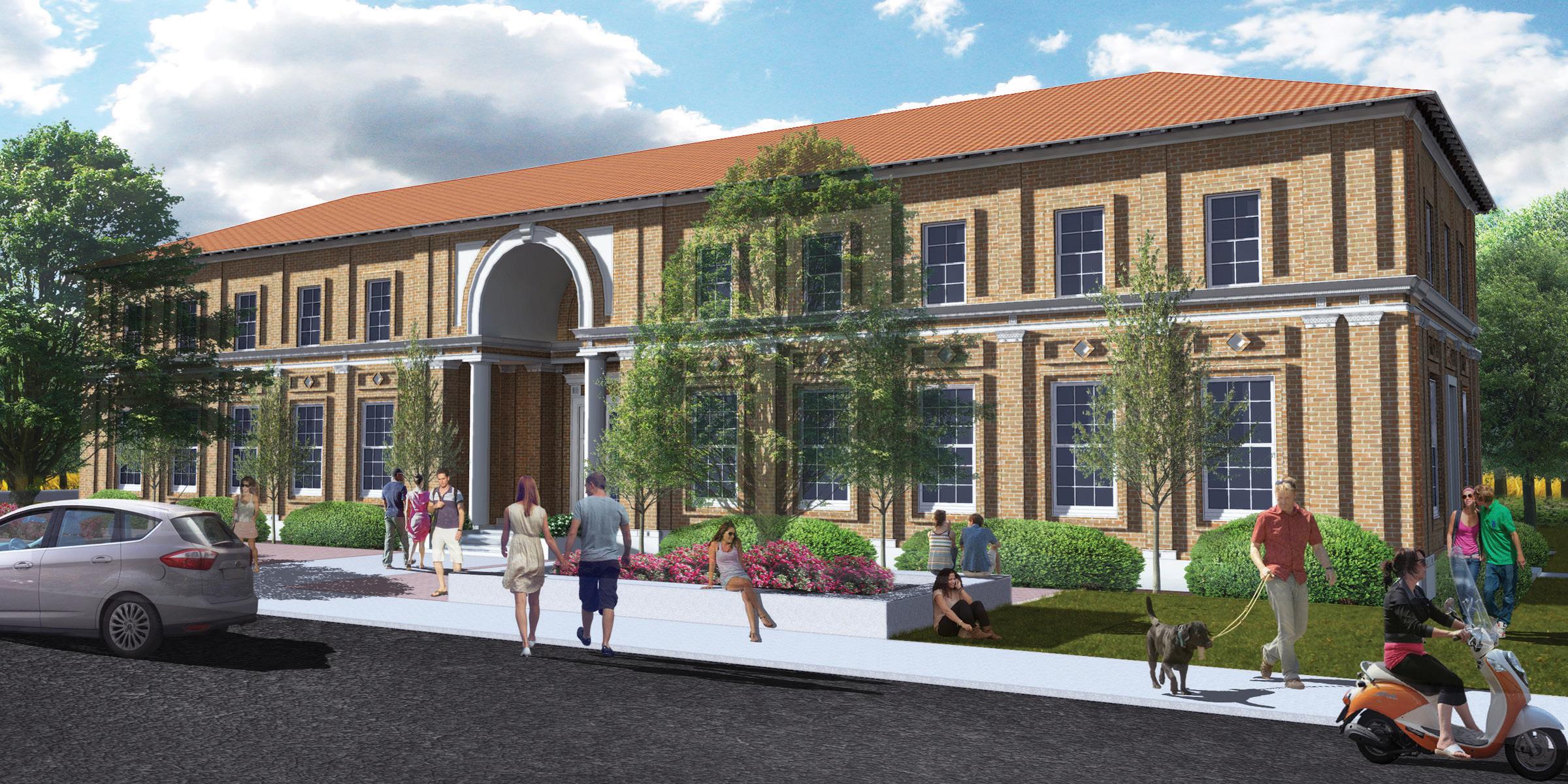
Figure 1. Rendering. Courtesy of Ravatt Albrecht & Associates.
Seismic Retrofi t of the Atascadero Printery
By Jillian van Enckevort, S.E.
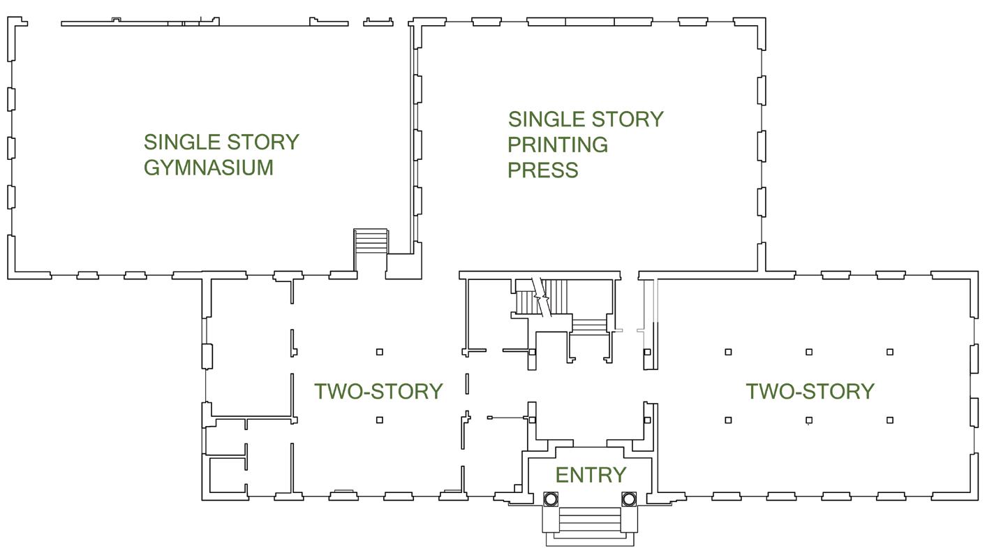
On December 22nd, 2003, the San Simeon Earthquake shook the central California coast damaging two historic unreinforced masonry buildings in downtown Atascadero. One of those buildings was e Printery, constructed in 1915 to house E.G. Lewis’ (the Founder of the Colony of Atascadero) printing operation. Since the earthquake, the building has been abandoned and has suff ered from vandalism over the years. In 2016, FTF Engineering was introduced to a non-profi t looking to purchase the building to transform it into a community arts building (Figure 1). e non-profi t, operating as e Printery Foundation, was able to secure ownership of the building from a public auction in 2017. e building was designed by Bliss and Faville Architects out of San Francisco and Engineer M.C. Couchot out of Oakland. e main portion of the building is a rectangular-shaped 2-story structure with a partial basement. At the rear is an original single-story room that housed the printing press and another single-story annex, constructed later, used as a gymnasium for a boy’s home tenant (Figure 2). e foundation, basement, and second fl oor are of concrete construction with ½-inch-square smooth bar reinforcing with unreinforced brick masonry bearing walls. e fi rst story walls are 4-wytheswide, and the second story walls are 3-wythes. Roof framing in the two-story section consists
of wood rafters spaced at 2 feet on-center, trussed with 1x bottom chords and webs with the hips supported on a steel truss at each end. e single-story portions have hipped roofs framed with long-span steel trusses and wood rafters between. Currently, the buildings are topped with metal roofi ng over straight sheathing, though there is a reference to a mission tile roof in the as-built drawings. In 2000, the building was nominated for the National Register of Historic Places and was offi cially added in 2004. e prominent historical features of the building include the Italian Renaissance terra Figure 2. Existing fl oor plan.
cotta ornamentation on the exterior of the building and the original Ralph Holmes tapestry murals and marble tile in the central lobby. The building required a seismic retrofit and, because of the historical status of the building, FTF Engineering and Ravatt Albrecht & Associates were able to use the 2019 California Historic Building Code (CHBC) to guide the analysis and retrofit. The retrofit focused on the four items of typical unreinforced masonry buildings known to result in the most damage and loss of life in major earthquakes: in-plane shear capacity of the brick, the out-ofplane bending capacity of the brick, anchorage of the walls to the roof/ floor, and weak flexible horizontal diaphragms. The CHBC references Appendix Chapter A1 of the 2013 California Existing Building Code (CEBC). For historic structures, the ideal retrofit minimizes the intervention, maximizes the strength of the existing elements, and adds new elements in specific locations where necessary.
In-Plane Strengthening
Initial retrofit concepts provided by the consultants hired by the city after the earthquake included the addition of narrow shotcrete panels at the corners of the building to serve as new lateral load resisting elements replacing the strength of the original walls. During the schematic design phase, FTF explored this option but determined that collecting the load and dragging it out to the corners of the building would be problematic with the current wood-framed roof to 3-wythe brick wall connection. Shotcrete panels would also add a substantial amount of mass to the structure, impede on the interior square footage, and concentrate the lateral overturning forces resulting in the need to strengthen the existing foundation. With an existing brick shear strength of 100 psi, based on testing and equation A1-4 (2013 CEBC), the team instead decided to explore the option of strengthening the masonry exterior walls to improve their in-plane shear strength. The best option was to team up with Simpson Strong-Tie to utilize their Fabric Reinforced Cementitious Matrix (FRCM, ESR-3506). The FRCM product was chosen over FRP because it is better suited to the unevenness of the brick surface and results in a finished plaster surface that matches what was historically in the interior of portions of the structure. The product will be installed on the interior faces of the walls to avoid disruption of the historic exterior. Heli-Ties will be drilled through the interior wythe of brick at a depth to reach the exterior wythe and a spacing of three feet horizontally and four feet vertically to tie the wythes together. The ties will be staggered vertically to support a diamond-shaped section of the brick wall. The design process for the use of the FRCM product includes determining the demand and the capacity of the individual unreinforced masonry wall piers and providing this information to the
Simpson engineering staff. Simpson then determines the thickness of the cement plaster and the number of layers of carbon fiber grid reinforcement needed to make up for the deficiency. They also provide supplemental calculations and drawings to accompany the SEOR’s design package. For The Printery, the code requires a minimum seismic design lateral force of V = 0.75SDSW/R, with an R = 1.5 for ordinary plain masonry shear walls and a cap of 0.4W for Risk Category III and IV buildings per exception 4 of section 8-706.1 (2019 CHBC). With an SDS of 0.777, the cap of 0.4W controlled the retrofit base shear value. For example, the wall piers at either end of the building were analyzed using equations Va = vmA/1.5 (equation A1-20; 2013 CEBC) for shear capacity and Vr = 0.9PDD/H (equation A1-21; 2013 CEBC) for rocking shear capacity. The wall piers were found to be controlled by rocking shear with a capacity of 7,315 pounds at the second floor and 10,523 pounds at the first floor. The demand on these panels were 14,665 pounds and 25,157 pounds, respectively, requiring a 1-inch-thick layer of cement plaster and two layers of Figure 3. Cracking at the southwest corner. reinforcement in the second story and 1.5 inches of cement plaster and four layers of reinforcement in the first story. The existing URM walls had sufficient capacity to resist the seismic demand in other locations with longer shear panels. Still, a single layer of fabric reinforcement with 1 inch of cement plaster was specified to help control the cracking of the brick during a seismic event. Out-of-Plane Strengthening Supplemental bracing must be provided where the wall height-tothickness ratios do not meet the requirements of Table A1-B (2013 CECB). The ratios vary based on whether the building has qualifying cross-walls (partitions) or not. The Printery contains large open-span spaces where cross-walls do not exist; therefore, the limits are 13 for the one-story building, 15 for the first story of the two-story building, and 9 for the second story. Analysis revealed that the upper story required bracing. HSS steel strong backs tied into the floor and roof diaphragms with epoxy anchor connections to the brick wall were used to brace the wall out-of-plane. The design lateral force is per A110.1 and meets the spacing/deflection requirements of section A113.5.2 (2013 CEBC). Out-of-Plane Wall Anchorage One of the most noticeable deficiencies of the existing building after the earthquake was the inadequacy of the anchorage between the walls and the roof. The walls showed signs of pulling away from the
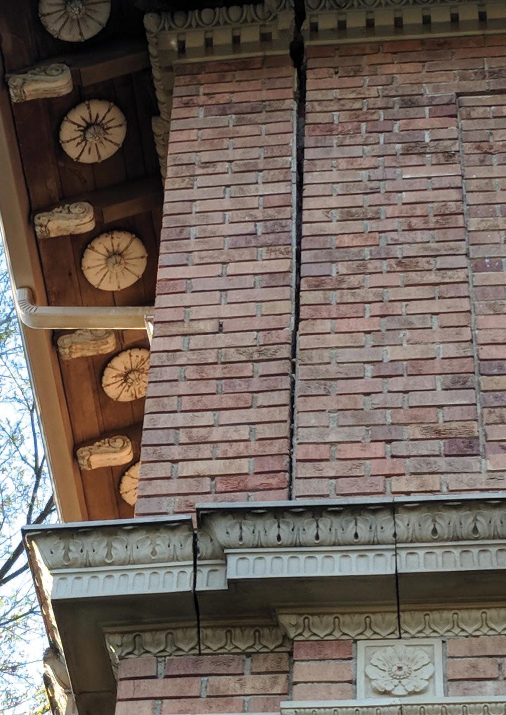
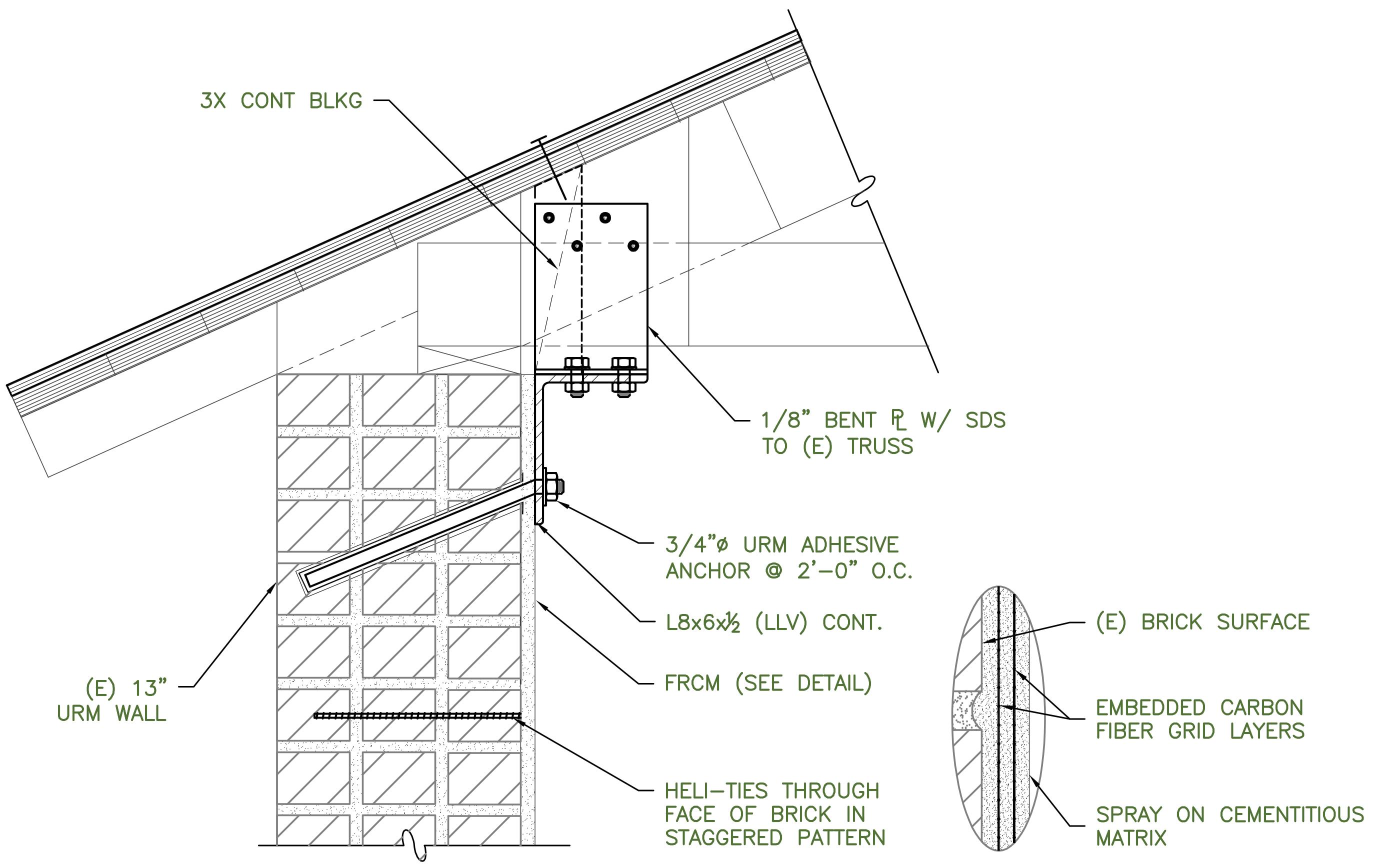
Figure 4. Wall-to-roof strengthening detail.
roof in numerous locations and have since been shored to prevent further movement and possible collapse. In the years since the San Simeon earthquake, the crack at the southeast corner of the building appeared to be worsening (Figure 3, page 35 ). In addition to adding shoring, a mason was hired to reconstruct the interior wythes of brick to restore the wall’s structural integrity. The typical roof-to-wall framing condition in the building has the roof rafters sitting on top of the URM walls with a 2x6 wood plate at the top of the wall. In the one-story portion of the building, the rafters are supported by trusses made up of steel angles spaced approximately 12 feet on-center. The trusses are set into and bear directly on the brick walls with short anchor bolts with limited lateral strength. Beneath each of the trusses is a section of brick wall bulging outward, signifying that the walls were pulling away from the roof during the earthquake. As part of the seismic retrofit, HSS posts have been added underneath any large point loads to help prevent roof collapse if the brick is damaged. The upper roof of the two-story section consists of rafters spaced at 2 feet on-center, trussed with 1x webs, and a built-up 1x bottom chord spliced at approximate third points. Per the CEBC, it is recommended that the walls be anchored to the roof system at a spacing no greater than six feet on-center, and the preferred method of attachment is to use a through bolt with an anchor plate on the exterior face of the wall. However, since this method would have caused a great deal of disruption to the terra cotta detail on the exterior of the historic building, it was not an option. Instead, a system consisting of epoxy anchors at a spacing of two to three feet on-center was used to reduce the design force per anchor while still significantly improving the expected performance in a seismic event. In most cases, a steel angle was designed to span continuously underneath the existing rafters/trusses with steel angle side plates extending up to tie into the rafters and transfer the outof-plane forces into the diaphragm. These details aim to simplify construction and reduce field welding wherever possible (Figure 4).
Diaphragm Strengthening
The diaphragm is the “glue” that holds all of the other pieces of the retrofit together; it transfers the loads from the out-of-plane anchors and strong backs out to the newly strengthened shear walls. Per the CEBC Table A1-D, Strength of Existing Building Materials, the existing straight sheathed diaphragms are adequate for 300 plf but, with the heavy weight of the building, it was determined that the minimum diaphragm force was 323 plf and a maximum of 686 plf. Since the metal roofs are at the point of needing replacement, ½-inch plywood overlay will be used to strengthen the diaphragms with nail spacing and patterns varying based on the required capacities. The plywood will be applied directly over the 1¼-inch sheathing, and 16-penny nails have been specified to achieve the required penetration. As an alternative, FTF provided an option for a diaphragm screw since the age of the wood framing can make it difficult for nails to penetrate the hardened wood.
Summary
While the deficiencies of most URM buildings are similar, the details of the retrofits are all very unique to the individual buildings. The Atascadero Printery building had its own set of challenges, including the irregular geometry, the historic nature of the project, and working with a nonprofit tasked with raising money to save the building. The first two items were solved with engineering and teaming with companies like Simpson Strong-Tie. The last led FTF to use creativity to design connections that do not require skilled tradespeople, permitting as much volunteer labor as possible to achieve the retrofit and stay involved in the organization’s fund-raising efforts. If you are interested in supporting the project and saving a piece of history, please see https://atascaderoprintery.org. ■
Jillian van Enckevort is a Principal of FTF Engineering and manages the San Luis Obispo office (jvane@ftfengineering.com).
Resilient
MILITARY HOUSING
By Anantha Chittur, P.E., S.E., and Frank K. Humay, Ph.D., S.E. Figure 1. Building confi gurations.
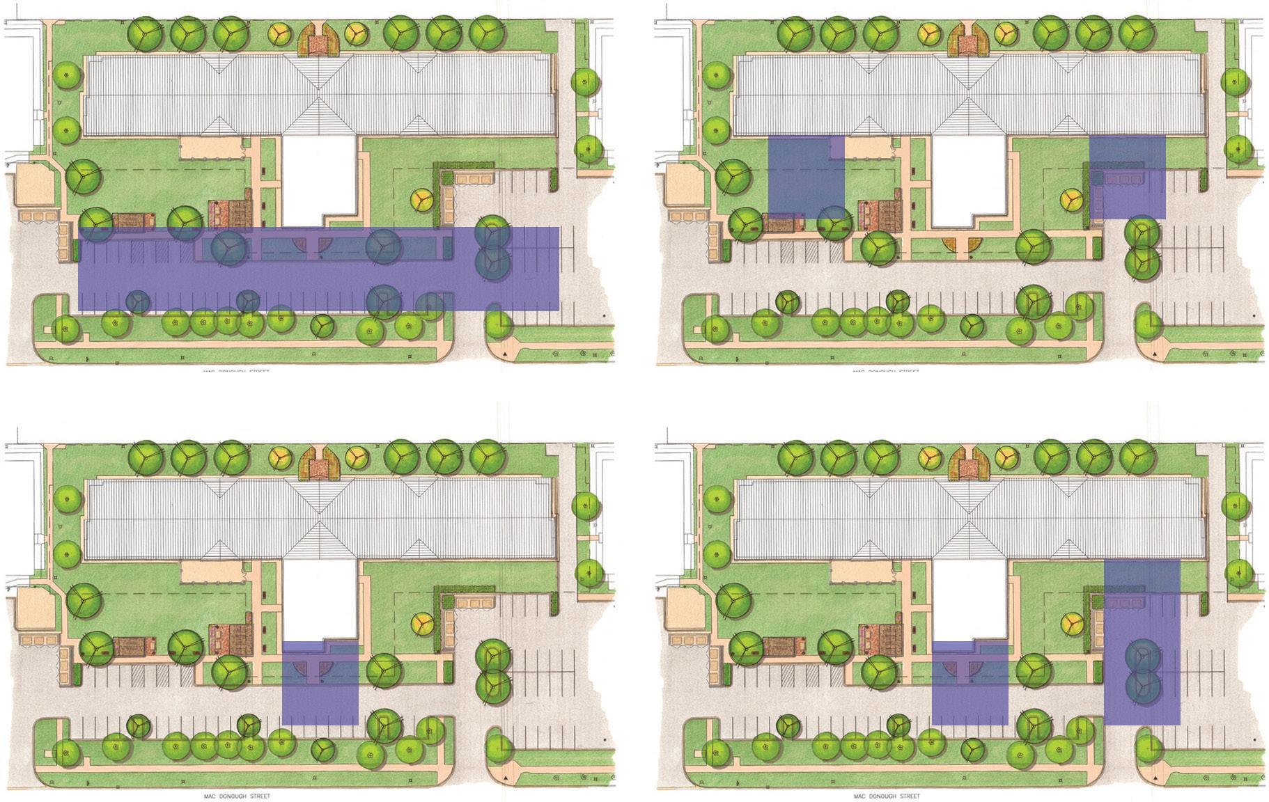
This Bachelor Enlisted Quarters (BEQ) project is a $60 million multi-story housing complex for enlisted military personnel. In addition to sleeping rooms, the facility includes an entry vestibule, quarterdeck, multi-purpose rooms, classrooms, laundry areas, and other support spaces. e T-shaped building results from multiple studies that considered site orientation and access, parking layout, view planes for future expansion, and more (Figure 1). e project was a competitive design-build procurement based on a Request For Proposal (RFP). e general contractor, design-build subcontractors, and A-E Team were involved in intensive pre-design sessions to explore various design solutions and associated costs. Pricing documents with suffi cient detail to budget the project were developed as a basis for the fi nal bid.
Building Description
e building measures 380 feet in the north-south direction with an 80-foot extension in the east-west direction. e six-story building is 71 feet tall with an exterior consisting of face brick with reinforced concrete masonry backing and a hipped standing seam roof supported on cold-formed steel trusses bearing on the concrete roof slab (Figure 2). Level 1 consists of a spacious centrally located quarterdeck, multipurpose rooms, and other administrative spaces. A total of 308 dormitory units are distributed along double-loaded corridors, maximizing daylight and views from the living quarters. Each unit has operable windows, which are punched openings in the exterior wall. Vertical circulation is provided through two centrally located passenger elevators, a freight elevator, and exit stairs located at the ends of the corridors. e design is in accordance with the 2015 International Building Code (IBC) and other applicable Department of Defense (DoD) Unifi ed Facilities Criteria (UFC). is Risk Category II building is designed for a wind speed of 115 mph and a seismic design category B.
Primary Structural Systems
ree diff erent structural systems were evaluated: steel framing with composite deck, precast concrete with hollow-core planks, and a castin-place concrete structure. e steel solution increased building fl oor-to-fl oor heights, added fi reproofi ng requirements, increased MEP distribution costs, and introduced uncertainties in steel costs due to new tariff s. In addition, the precast system proved diffi cult to meet the progressive collapse requirements. e cast-in-place system was selected because it provided the greatest fl exibility, lowered the building height, reduced MEP distribution costs, and insulated the schedule from supply chain delays. e fl oor and roof framing consists of conventionally reinforced two-way cast-in-place concrete
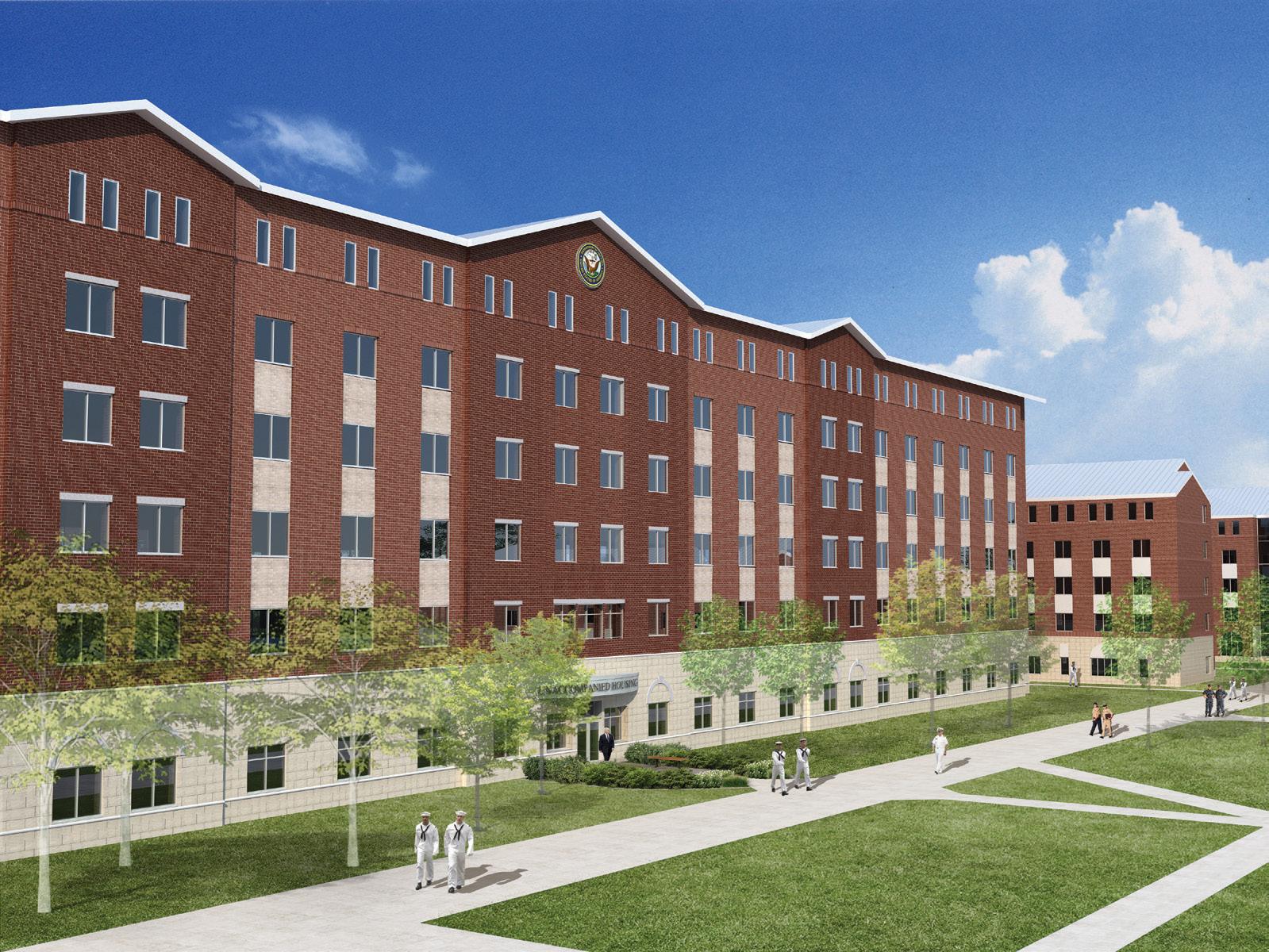
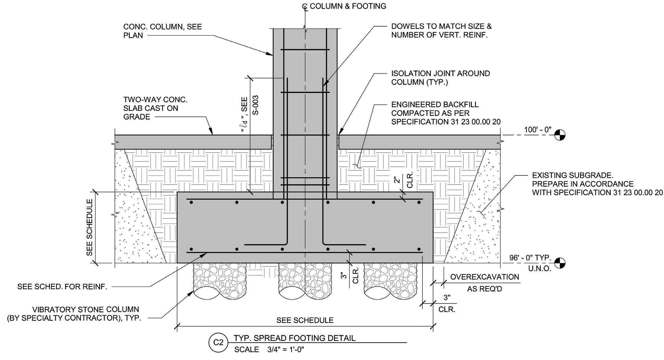
Figure 3. Rammed aggregate pier foundation with hybrid slab-on-ground.
slabs that are 8.5 inches in thickness with spans in the range of 18 to 27 feet. The exterior columns are inset from the perimeter, creating cantilever end spans. Interior columns consist of wall columns in the demising walls and rectangular columns. Column location and configuration was chosen to create a feeling of openness in the living quarters. The lateral force-resisting system consists of ordinary reinforced concrete masonry shear walls with a modular layout on the perimeter and supplemental interior ordinary reinforced concrete and masonry shear walls. In addition to providing a highly redundant lateral force-resisting system, multiple hazards are addressed by the exterior masonry walls. DoD UFC criteria mandated blast-resistant construction. Progressive collapse avoidance was also considered in the design due to the building’s height. Rigid diaphragms are used to transfer lateral loads.
Hybrid Slab-on-Ground
The slab-on-ground also involved an unconventional approach. A hybrid approach with selective soil replacement was used as an alternative to a slab either fully supported on stone columns or structural fill (Figure 3). Compacted structural fill is placed over the footprint of the foundations (supported on stone columns) to act as “rigid” supports, reducing the slab clear span. The slabs have isolation joints around the columns and were analyzed as conventionally reinforced two-way slabs supported on springs representing different moduli of subgrade reaction (150 pci at the foundation and 10 pci for the native soil). Studies were performed to ensure that the maximum live load settlement is less than ¼ inch. The hybrid approach resulted in a thinner slab (7.5 inches) with reduced reinforcement compared to a conventional structural slab-on-ground.
Foundation System
This project is constructed on a site left vacant by the demolition of an existing building. As a result, the site contained uncontrolled fill materials and building demolition debris (e.g., pieces of concrete, brick, wood, etc.). It was not suitable to support a six-story building without remediation. The RFP recommended compaction grouting to improve the site. After a careful evaluation by the design-build team, it was determined that compaction grouting was not viable, and several alternatives were assessed. Another alternative involved the removal of 6 feet of existing soil and replacement with structural fill, but this option was rejected due to significant added cost and impacts to the project schedule. The final solution supported the structure on shallow concrete foundations bearing on vibratory stone columns (also known as rammed aggregate piers). In addition to its suitability for this site, the strength and stiffness of the piers can be reliably quantified using modulus load tests. The stone columns are typically 2 feet in diameter and extend 8 to 17 feet below the uncontrolled fill material.
Building Resiliency and Hardening Considerations
DoD buildings are designed with enhanced life safety provisions per the Unified Facilities Criteria requirements, available on the Whole Building Design Guide website (www.wbdg.org). This facility was designed for blast resistance and progressive collapse avoidance (i.e., disproportionate collapse). Design requirements for blast resistance are project-specific and vary for each project. Facilities with at least three inhabited stories are designed to prevent disproportionate collapse caused by a loss of structural support in accordance with UFC 4-023-03 Design of Buildings to Avoid Progressive Collapse. Multiple design methods are prescribed in that document, and the applicability is determined based on the risk category of the facility. Due to the framing and geometry of this project, the alternate path method was used, which requires the design to consider the removal of individual vertical load-supporting elements around the perimeter of the building and provide a viable alternate load path. continued on next page
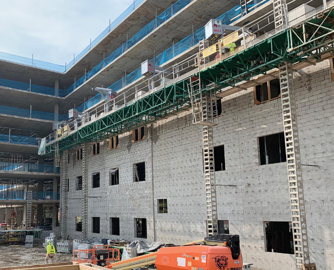
Figure 4. Masonry construction using MULE.
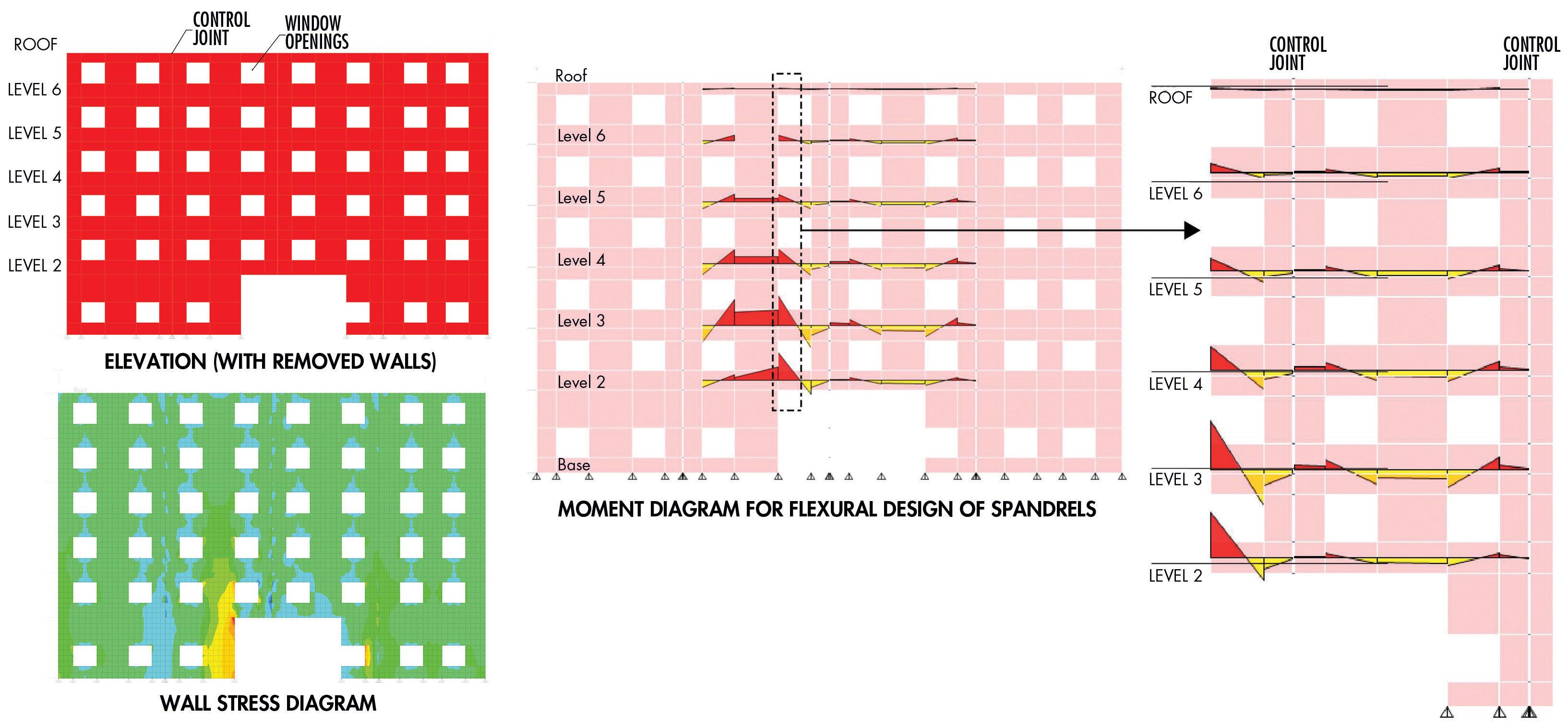
Several structural schemes were evaluated, including perimeter columns with uniform spandrel beams on each floor or a single transfer girder at the roof. The layout of the rooms of the building constrained the location and spacing of the columns. Due to the modular design of the building, removing an exterior column effectively doubled the span length of the beams. Removing outside corner columns created a two-way cantilevered beam condition. Due to architectural constraints, the beam sizes required to support these design options were too large and costly. The final solution developed by the structural design team addressed architectural functionality, minimized material costs, and helped shorten the construction schedule by insetting the perimeter columns and relying on Vierendeel truss action of the masonry walls.
Multi-Functional Masonry Wall
The building’s exterior is constructed with reinforced concrete masonry that also provides resistance to lateral wind and seismic forces. In the original design, the masonry wall also supported the edge of the concrete slabs. However, this required that the masonry wall and concrete frame be constructed concurrently, which would have increased construction time and cost. Concrete columns, inset from the exterior walls, were added so that the construction of the concrete frame was independent of the masonry. Material Unit Lift Enhancers (MULEs), along with jumbo masonry blocks, 8-inch by 32-inch and 74 pounds in weight, were used to increase productivity and safety (Figure 4). The exterior masonry wall enhances the redundancy of vertical load paths in the building. If a portion of the exterior masonry wall is removed, the loads from the unsupported walls above are redistributed to adjacent wall segments through Vierendeel truss action. Reinforced masonry bond beams at headers, sills, and floor levels and the window jambs are designed for the resultant axial, flexure, and shear forces. Smooth dowels at masonry control joints permit horizontal movement due to temperature and shrinkage while allowing vertical shear load transfer (Figure 5). The masonry walls are built outboard of the concrete slabs but connected to them to transfer in-plane and out-of-plane loads. The connections allow the masonry to deflect vertically without imposing additional loads on the cantilever slab when a section of the wall is removed. Detailed deflection analyses were performed to verify the slab deflection at the cantilevered slab edges, and, where necessary, the formwork was cambered. The two-way slabs performed well with minimal unanticipated deflections.
Conclusions
The structural design for the project overcame several challenges through close collaboration between the various design team members and the client. The team continually improved the design when opportunities arose, and constant effective communication and timely decision-making were critical in the fast-track delivery of this building, a functional, efficient, and resilient home for our military for many decades to come.■
Anantha Chittur is Senior Associate at BASE and is based in its Chicago office (achittur@baseengr.com). Frank K. Humay is Vice President at BASE and is based in its Honolulu office (fkh@baseengr.com).
