34 minute read
Structural Failures
Avoiding Failures in Concrete Structures
By Hee Yang Ng, MIStructE, C.Eng., P.E.
Reinforced concrete is a construction material widely used in many applications, including buildings, bridges, and other infrastructures. Due to its massive size and various redundancies, concrete structures are often considered solid, robust, and safe. However, there have been instances of concrete structure failures and collapses, many due to erroneous assumptions or oversight by the designers in evaluating the design situation or poor construction practices. This article highlights several design and construction situations that designers and builders should pay special attention to in order to prevent failures.
Design of Silos
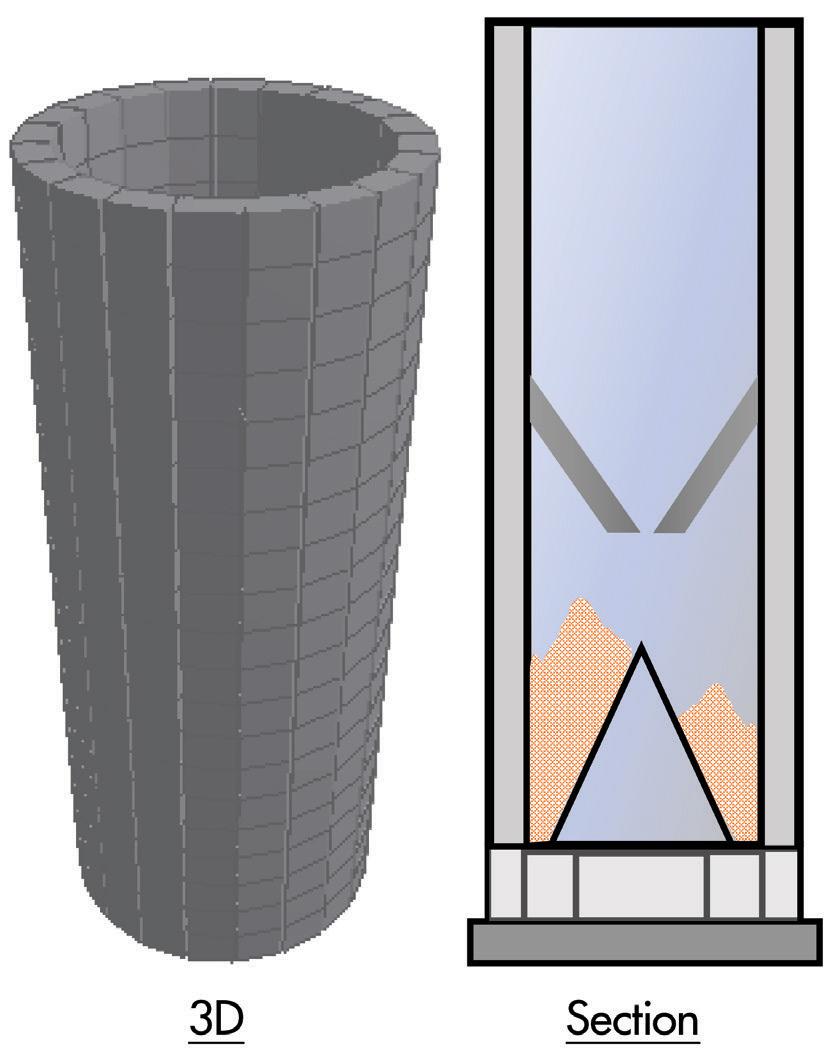
For example, some grains are known to absorb moisture and cause additional loads due to swelling of the grains. This example illustrates the importance of determining as accurately as possible the type of loadings exerted by different materials onto a structure, including loading magnitude, direction, and possible permutations in area. Detailing a concrete silo with a single layer of reinforcement to deal with hoop tension only by assuming symmetric loadings would clearly be inadequate.
Effective Width of Support Member
Silo structures are notoriously known to many as a structure requiring special attention, not because of the external loads, such as wind or seismic, but due to the storage load of the bulk solid. The unwary designer might unrealistically simplify and assume the load to be hydrostatic pressure caused by a fluid, even though the actual storage material might be solid granular material or particulate in nature. The force exerted by particulate materials onto a silo container can be different. First, the designer must consider conditions during the filling up of the silo and discharging of the materials. There might be instances of eccentric loads (Figure 1) and higher loads (e.g., impact) caused by these processes. Next, there must be consideration of whether the presence of moisture, gas pressure, or other ancillary equipment imposes additional loads.
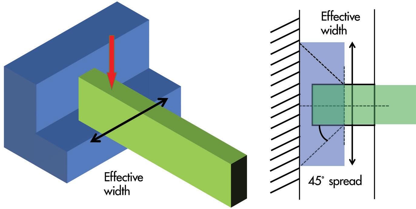
Consider a case of a concrete support structure with a wide corbel (or nib) to catch an incoming beam (Figure 2). Due to its short length compared to its depth, the design of the corbel should not be based Figure 1. Non-uniform loading on silos. on a bending formula. Instead, a strutand-tie model would be more appropriate to work out the necessary reinforcements to resist the load. However, there is still a need to work out the effective width of the corbel used in resisting the load and not assume the entire width of the corbel can be used. To work out the effective width, designers can refer to guidance on effective slab width at exterior slab-to-column connections, where a 45-degree spread from the centerline of the column is recommended. There may be a larger angle of spread if the transverse stiffness of the corbel is high, making it very rigid (e.g., thicker section or higher reinforcement ratio). But an overestimate of the effective width might give rise to over-prediction of capacity and result in design deficiency of this critical structural element. Underdesign of such low redundancy structural elements (e.g., cantilevers, simply supported beams) can be very dangerous because there is no alternative load path for redistribution, and failure is often likely to occur. Therefore, correctly selecting the effective width can be a crucial design aspect.
Nib Failure
One common way to support a brick wall façade is by designing a nib. Because of the small bearing length of the nib, it is necessary to place the reinforcements precisely. This ensures that sufficient bearing length of the nib is reinforced with reinforcement bars. Suppose the reinforcement bars were placed short, resulting in extra concrete cover,
or worse, using additional thicker plaster to achieve the required length. In that case (Figure 3), the unreinforced portion of the nib can easily be dislodged under the weight of the bricks. is example highlights the dangers of having extra concrete cover and failure in the unreinforced zones in a structural member, especially when such unreinforced zones are required to support heavy loadings.
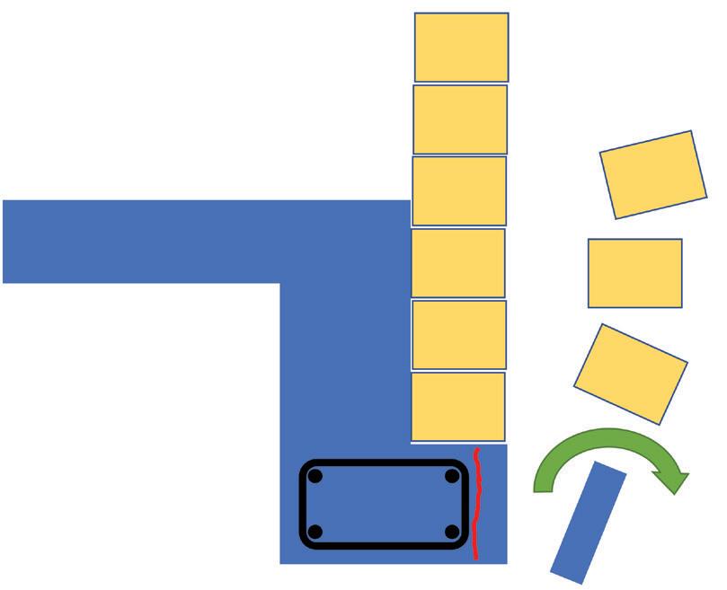
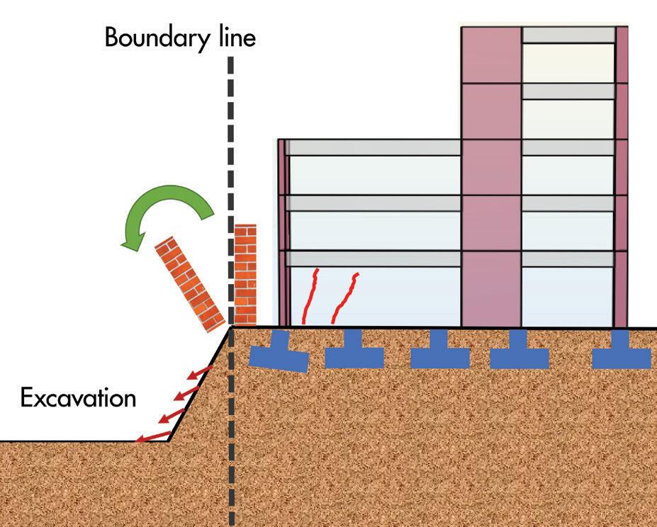
Figure 3. Nib failure and works near existing buildings.
Cracks at Joints and Discontinuities
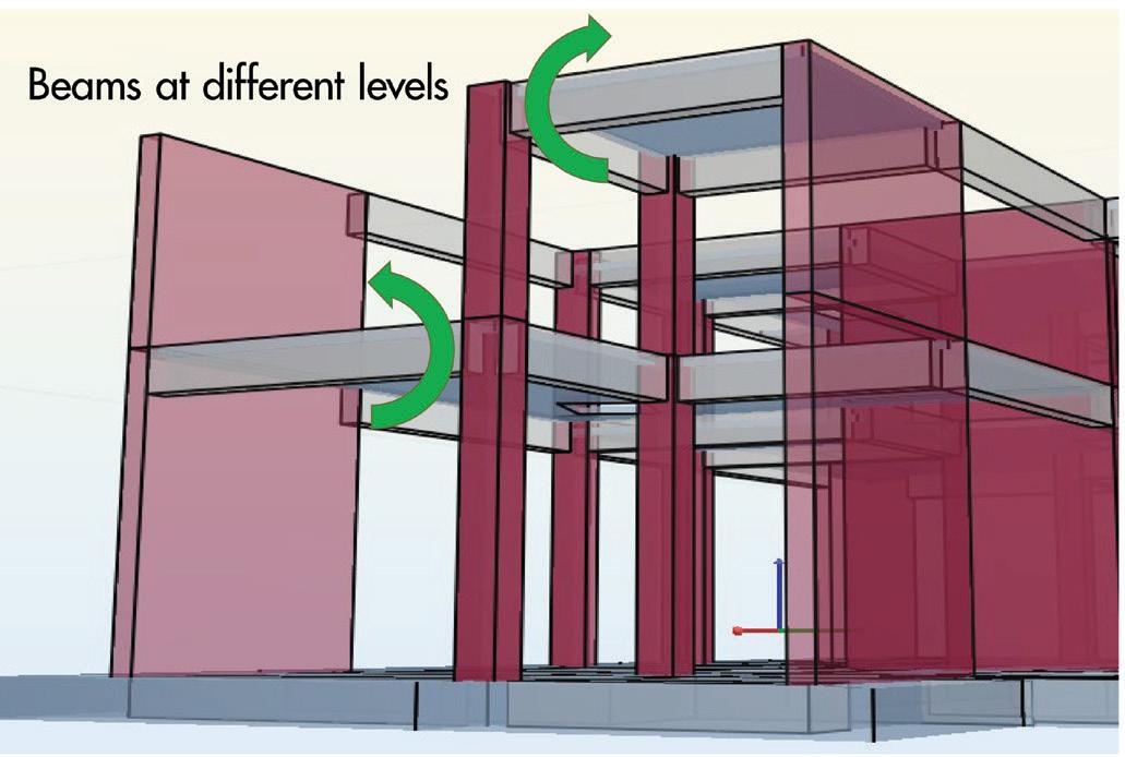
In concrete structures, high stress concentrations can occur in regions such as turnings and kinks (e.g., connecting truss members and inclined members, Figure 4, page 24). In addition to correctly identifying the type of actions to be resisted (i.e., axial, shear, bending, and torsion) by a particular structural member, it is necessary to detail the reinforcement bars correctly. Members that are not strictly beams (dominantly bending and shear) or columns (dominantly axial load) could potentially be subjected to a combination of more than one dominant action. e detailing process can become diffi cult due to awkward geometry and diffi culty fi tting bent bars in tight spaces, which may sometimes result in extra concrete cover that may not necessarily be desirable and could sometimes result in cracking. Splicing of reinforcing bars (especially if spliced all in one location) may introduce a weakness at the location of bar discontinuity. When bars need to be discontinuous, splicing should be staggered and preferably avoid highly stressed regions. Another design situation requiring attention is beams framing into columns at diff erent levels on opposite sides. Designers should know that the opposite direction moments do not equalize and design for the actions imposed by such a confi guration. is can be a more common issue in concrete construction, where there is often some fi xity at the joints.
continued on next page
ADVERTISEMENT–For Advertiser Information, visit STRUCTUREmag.org
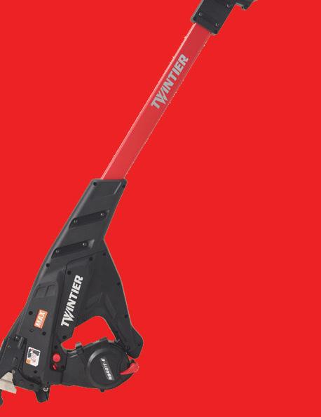
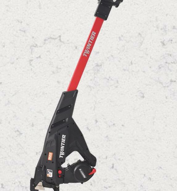
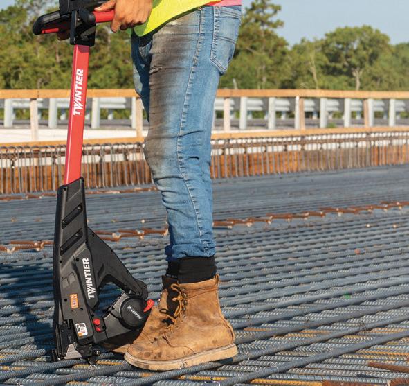
FINISH REBAR TYING FASTER WITH
SAVE TIME SAVE MONEY DOUBLE THE TYING SPEED SHORTER TIE HEIGHT
The Wire Pull Back Mechanism dispenses the precise amount of wire needed to form a tie. The Dual Wire Feeding Mechanism increases productivity on job sites. The TwinTier®’s Wire Bending Mechanism produces a shorter tie height. Less concrete is needed to fully cover a wire tie.


SCAN TO VISIT OUR WEBSITE
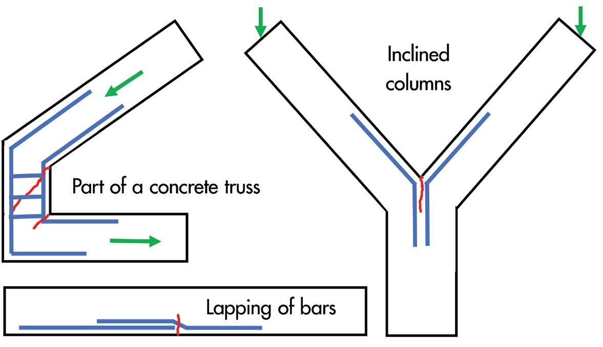
Figure 4. Cracks at joints and discontinuities.
Flat Slabs to Span Full Load in Two Directions Works Near Existing Buildings
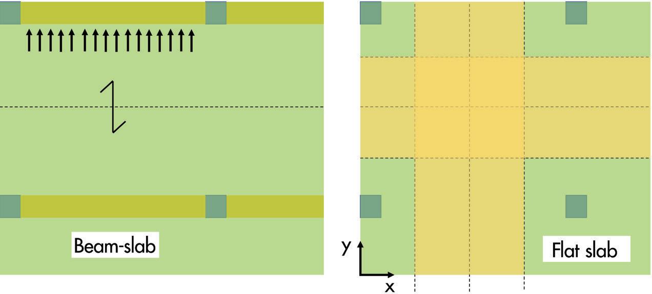
When designing a flat slab system (Figure 5), designers need to note that the full load must be taken in the two orthogonal directions independently. Some designers mistakenly assume the flat slab system behaves similarly to a two-way spanning slab and underestimate the loading and bending moments, resulting in inadequate reinforcements. They might have distributed the full load in two directions (each direction taking one half) or designed for the full load in one direction but totally missed out the orthogonal direction. This misconception could have come from designing a one-way spanning slab where only one direction of spanning (the shorter span) of the slab is required. The other direction is also taking the full load but in the form of the beam and not the slab. In a different scenario, some builders who are not familiar with beam-slab design may assume that a longer span is always more critical and be tempted to place larger reinforcement in a slab (with full beam supports) in the direction of the longer span, not knowing that the larger moment actually occurs in the shorter span. While builders are not expected to carry out structural design, they should still appreciate basic structural behavior and reinforcement placement concepts. In many city centers and highly urbanized built-up areas, new development works might inevitably be located close to an existing building. The situation worsens if any excavation for basement or foundation works is required. Some builders make the mistake of excavating right next to an existing boundary wall, not knowing that such excavation work can undermine the foundation of the boundary wall and can cause it to topple (Figure 3). When ground movement is not appropriately controlled (e.g., open-cut excavation), the adjacent building’s foundation may experience movement (lateral and vertical) and cause damage to the super-structure. It is thus necessary to adopt an appropriate earth-retaining system that can limit the ground movements to acceptable levels. It may even be necessary to strengthen the adjacent structures’ ground or foundation in certain circumstances. Similarly, digging in front of a retaining wall may cause the wall to be weakened, as passive resistance in front of the wall is reduced when soil is excavated. This scenario can occur in hilly areas where retaining walls retain slopes and create usable areas. An overly-zealous contractor could commence excavation in front of a retaining wall without knowing such works could trigger a collapse. It is safer first to understand how construction works would impact the adjacent buildings and structures and then design a safe work procedure with strengthening measures to ensure that the existing retaining wall stability is safeguarded during any digging.
Temporary Support during Construction
There are two main areas to note during reinforced concrete construction: the support of the reinforcement bars and the wet concrete during pouring concrete. Reinforcement bars require some support to hold them in position before concreting. In very thick concrete elements, such as raft foundations or transfer plates, the area of reinforcement bars is likely to be correspondingly large. Some builders might overlook the lateral support required for such heavy top bars and rely on stirrup-type support to hold up these bars. For such cases, it is necessary to design a bespoke support system with adequate lateral bracing to prevent side-sway failure (Figure 6). Formwork to support wet concrete needs to be snugly

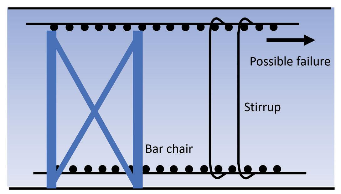
Figure 6. Temporary support during construction.
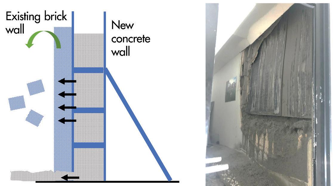
fi tted and free of gaps that may allow concrete to fl ow through. is may sometimes be diffi cult when there are gaps in sloping or uneven ground. When concrete must be cast adjacent to an existing structure, builders must be mindful not to impose additional loads onto the existing structure. For example, such existing structures could be made of a brick wall with little capacity to resist the heavy lateral loads imposed by wet concrete (Figure 6 ). In addition to designing formwork to take lateral loads, the designer also needs to ensure the overall concrete section or element to be cast does not lean onto the existing structure.
Summary
Specifi cations and Quality Control
Concrete structures can sometimes fail during service life for various reasons, such as deterioration (spalling due to rusted reinforcements), attack by aggressive environments, lack of maintenance, overloading, or unauthorized alterations. erefore, correct specifi cations and quality control during construction are critical in ensuring concrete is durable to withstand weathering in its environment. Designers must pay attention to the exposure class and comply with requirements on minimum compressive strength of concrete, cover, cement content, etc. In highly aggressive situations, it may be necessary also to have special additives and protective coatings on reinforcement bars. Supervision and quality control during construction ensures that specifi cations on paper are met on-site, from concrete production and delivery to handling, placement, and curing. Building owners should be informed by the designers on the usage of the building and be briefed on allowable loadings on fl oors, maintenance requirements, and not to make unauthorized alterations. Any unusual sightings of distress (e.g., cracks, deformations, settlement) should be referred to a qualifi ed professional for assessment. Carefully designed reinforced concrete structural elements should have suffi cient ductility and should not fail by sudden rupture or instability. Many mishaps can thus be avoided if building owners and occupants pay attention to signs of distress and take early and timely interventions to evaluate and remedy the situation.
Safe design and construction of reinforced concrete structures require attention to detail. First, the designer can select an appropriate structural system to resist the loads by understanding loadings and load path. Special attention should be paid to silos and fl at slabs. Next, it is necessary to appreciate the concept of eff ective width when evaluating a section capacity under concentric load. Reinforcement detailing and placement on-site are also important aspects to pay attention to in order to avoid cracking and failure of unreinforced zones of a member. e builder should always remember that wet concrete during placement and heavy reinforcements require robust temporary supports. e various failure modes should be fully understood to avoid underestimating the potential for failure. Correct specifi cations and quality control during construction ensure durable structures to prevent premature deterioration. In addition, building owners and occupants have a role in ensuring the continued safety of a building in its service life by performing periodic monitoring and maintenance.■ Hee Yang Ng is a Principal Engineer with a building control agency in the Asia-Pacifi c region. ADVERTISEMENT–For Advertiser Information, visit Pour strips Wall restraint Expansion joints PS=Ø® eliminates: Reduces costs Accelerates construction Improves safety Increases slab quality STRUCTUREmag.org
Without PS=Ø® With PS=Ø®
No leave-outs ACI-permitted Type 1 & Type 2 ICC-approved Made in the USA
pourstrip0.com 800.355.8414 PS=Ø®


Lindquist


Hall Remodel and Seismic Renovation

By Jeremy L. Achter P.E., S.E., LEED AP
The old Social Science Building at Weber State University, located in Ogden, Utah, was constructed in 1970. Programmatically, the building has been one of the most heavily used on campus, serving the social sciences, humanities, and many other departments throughout its life. One would be hard-pressed to fi nd a graduate of the University who had not taken a class there. Th e concrete building, consisting of one fl oor below grade and three fl oors above, remained largely unchanged in its 45-year useful life. Th e University’s wish was to completely remove and replace the antiquated mechanical and electrical systems within the building and redesign and reconstruct the architectural space to better serve the ever-evolving student population. Lindquist Hall, as the building would be renamed, is located in Northern Utah, within one-half mile of the Wasatch Fault and in Seismic Design Category D. An initial feasibility study was undertaken to determine an order of magnitude cost-estimate comparison of a complete remodel and seismic upgrade versus demolishing and replacing the entire building. Th e feasibility study resulted in a decision to keep the building, selectively demolish it down to the structural bones, and rebuild it. Th e electrical, mechanical, and civil consultants were tasked with designing completely new systems that complied with the 2015 International Building Code while fi tting within the confi nes of the existing structure and the new architectural program, and minimizing impacts to as much of the existing building as possible. Th e Structural Engineer of Record (SEOR) was responsible for developing and designing a complete seismic upgrade system for the building. Every fl oor level consisted of topped pre-cast double tees, and the roof consisted of un-topped single and double tee pre-cast joists. Th e joists were supported on a combination of cast-in-place and pre-cast girders that were in turn supported on cast-in-place and pre-cast concrete columns or the walls of two separate cast-in-place concrete interior stair towers and a mechanical shaft. Th ese three concrete cores were the lateral force-resisting system for the building. In addition to the full seismic upgrade, structural repairs, structural modifi cations, and new structural elements required for the
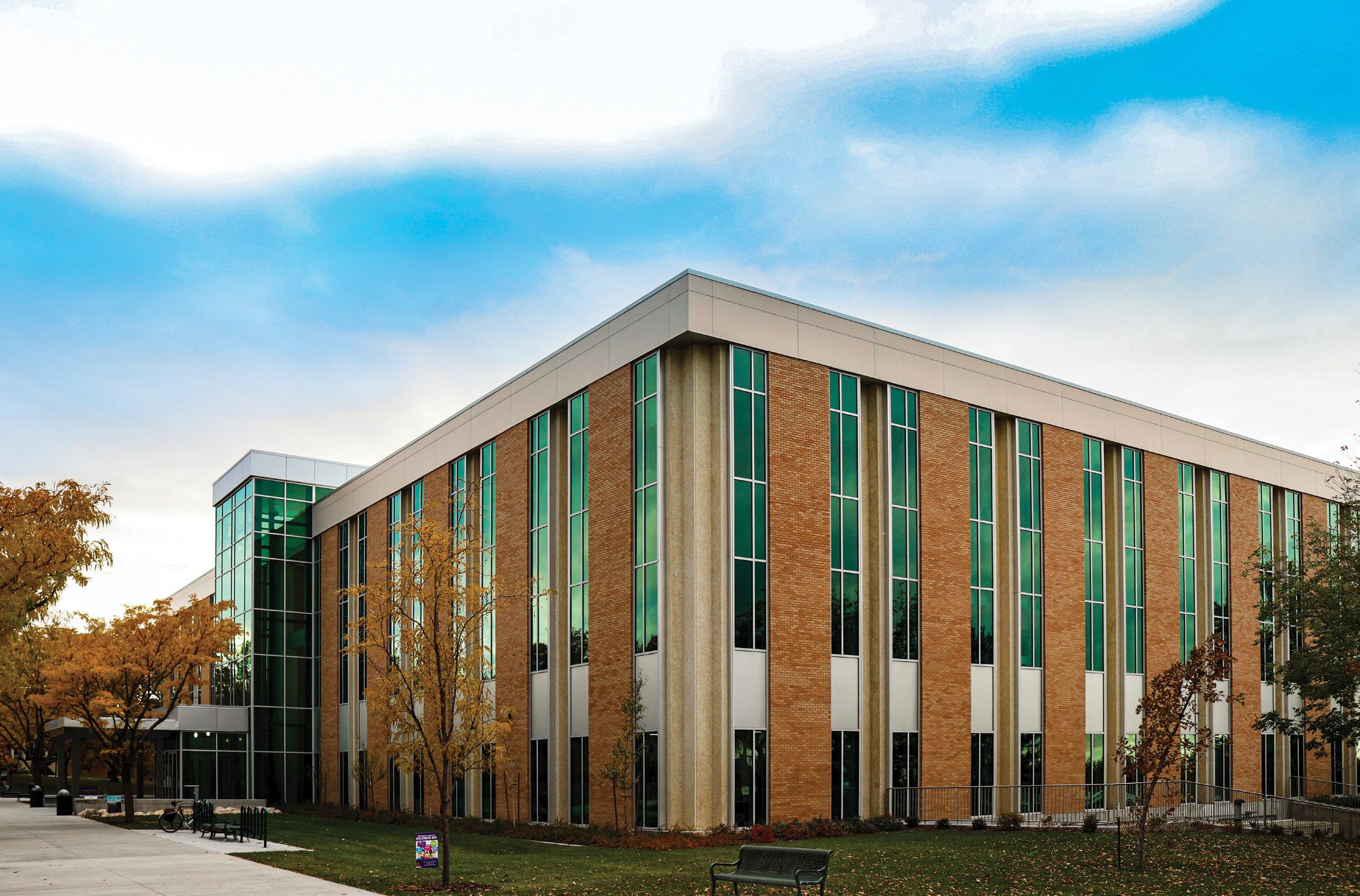

architectural program were designed and detailed. Some of these architectural elements included installing a new elevator shaft within the building footprint, removing two separate areas of floor structure near the building perimeter to create open continuity between multiple floors, and inviting natural light into the core of the building through strategically placed curtain wall systems. The building envelope was also completely replaced with metal stud, and a brick veneer system was placed outboard of the existing slab edge by approximately 16 inches, necessitating the extension of the floor slabs. Several challenges were identified through an in-depth structural evaluation, and solutions were developed. • The inherent lateral force resisting consisting of the core walls was insufficient in strength and ductility to brace the building.
Solution: De-couple the existing building from the existing shear wall system and replace it with a modern, ductile, well-performing buckling-restrained braced frame (BRBF) system. This task proved difficult because the concrete cores had to remain intact and support the gravity loads imparted by the concrete girders and joists connected to or bearing on the shaft walls. • The building was extremely heavy, resulting in very large seismic forces.
Solution: Remove the existing, non-performing, un-topped, very heavy pre-cast double-tee concrete roof system and replace it with a light, steel roof framing system with a design-as-required new metal deck diaphragm with necessary chords and collectors. This solution served a double purpose by significantly reducing mass and facilitating the new design of an appropriate roof diaphragm. • Existing pre-cast concrete cladding panels, and their connections to the structure, were determined to have insufficient strength and no ductility to resist out-of-plane seismic and wind forces.
Solution: Remove all the cladding elements from the building and replace them with a combination of new brick veneer backed by cold-formed metal framing and curtain wall systems. At the time of the initial design and construction, earthquake design was in its infancy, so seismic detailing, including adequate diaphragms with appropriate chords, collectors, and shear transfer elements, shear
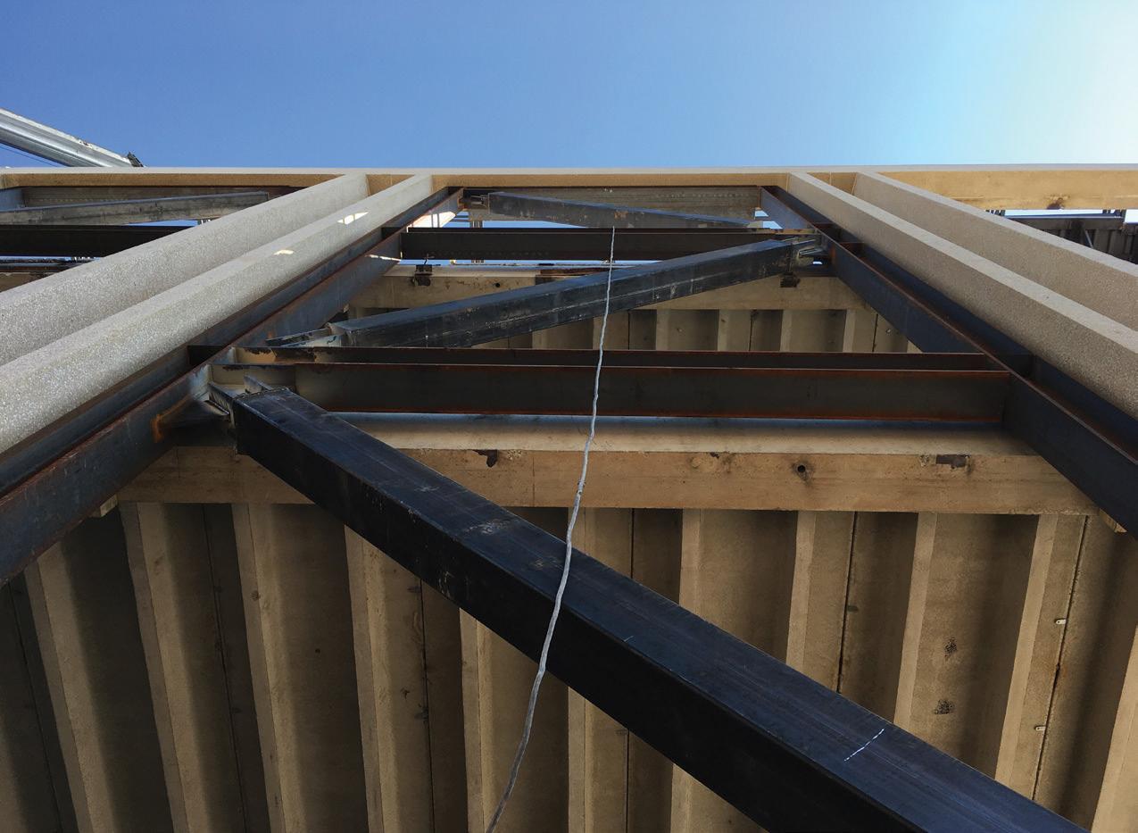
Figure 3. A new BRBF was installed in-plane with the pre-cast concrete columns and outboard of the floor girders.
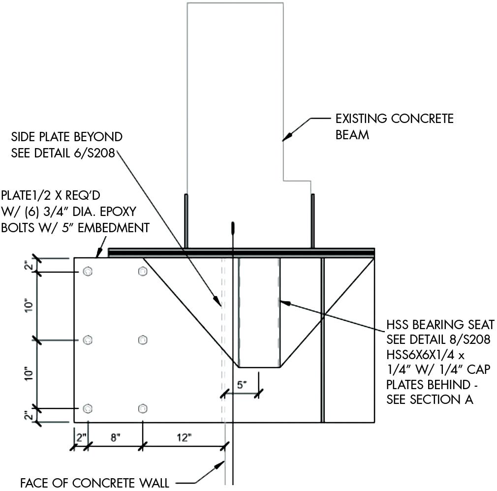
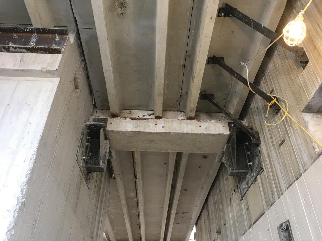
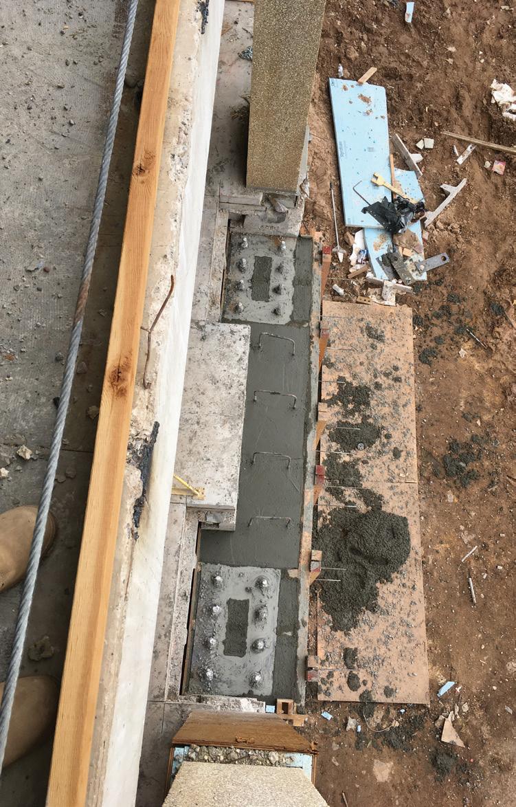
wall designs with adequate reinforcing and boundary elements, etc., was essentially non-existent. Throughout the building’s life span, a plethora of MEP openings were added to the walls that compromised the integrity of the lateral force resisting system. An extensive predesign testing protocol identified concrete strengths and reinforcing patterns and was used to calculate existing floor diaphragm capacities. The diaphragm was determined to have adequate shear strength but lacked the required chords and collectors. Furthermore, the diaphragm lacked continuity across girder lines where the topping slab was poured flush with the tops of the girders. Therefore, carbon-fiber overlays were designed and installed to create chords, collectors, and diaphragm continuity across discontinuous planes where required on three floor levels. The decision to remove the existing roof and replace it with a steel structure was also reviewed programmatically to determine the most economical solution. An independent cost estimate determined that the cost to remove the concrete and replace it with steel would result in a subsequent weight reduction and reduced seismic upgrade requirements. The decision to remove and replace the concrete roof with steel resulted in a cost savings of approximately $1,400,000. The existing shaft walls are effectively removed from the lateral force-resisting system to allow the new BRBF system to perform as intended. The amplified lateral drift was determined at each level; the intent was to free the upgraded structure from the shaft walls. To accommodate this, while the floor’s shafts actively supported joists and floor girder loads, each girder was cut back to allow up to 3 inches of lateral movement in any horizontal direction at the floors while maintaining gravity support of the in-place floor dead and subsequent required live loads. In addition, the structure was designed to pass over and rest upon the concrete cores at the roof level while allowing up to 5 inches of lateral movement in any direction at the roof level. The complex design to support the concrete girders involved a double slide bearing system. Large epoxy-bolted brackets were designed to attach to the core walls with robust bearing seats to support concrete beams that now terminate up to 3 inches from the wall. The double
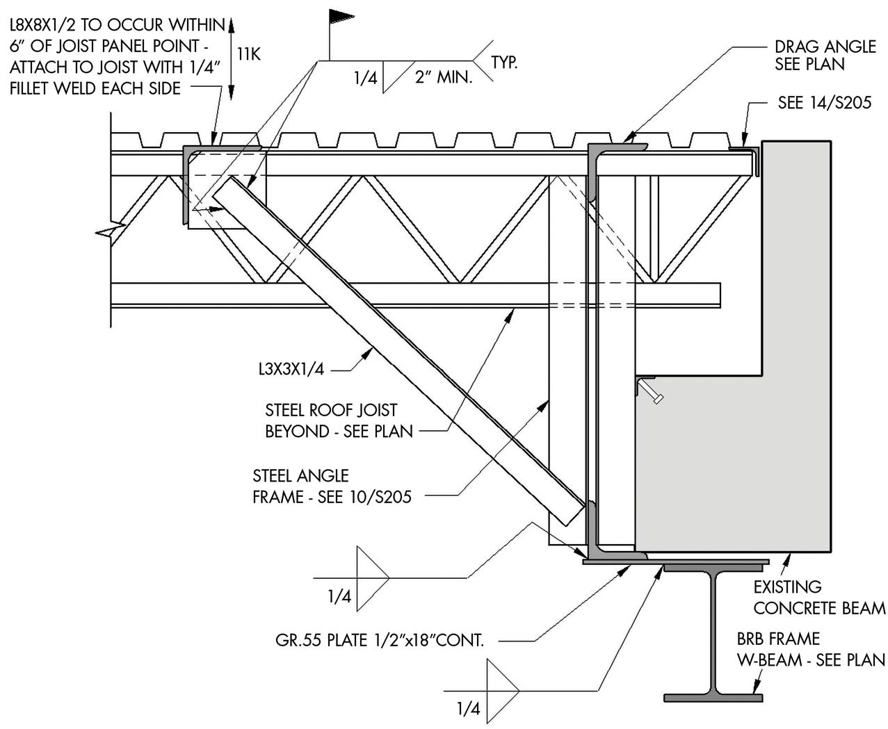
slide bearings consist of Teflon slide bearing brackets positively connected to the beams and slide bearing plates inversely connected to the bearing seats that allow for necessary slide in two directions while maintaining gravity load-carrying ability. To justify this approach, the existing concrete stair towers and mechanical shaft were analyzed to verify their ability to free-stand within the building, not to impart lateral loads to the structure, or, inversely, to take lateral loads from the structure. De-coupling the existing building from the existing concrete cores proved to be a complex task. The girders connecting to the shafts and the shafts themselves are all cast-in-place and essentially poured monolithically. The girders are inverted ‘T’ shapes where the pre-cast tees rested upon the the T's horizontal leg. Because there are many different bearing and connection conditions where the girders support different tributary lengths/areas, the centroid configuration of each girder connection to the shaft was inconsistent in its placement, and the amount of drift accommodation was different at each level of each girder, the reaction does not necessarily coincide with the centroid of the shape. Because of these nonuniformities, each girder bearing end condition is different, and each new steel plate bracket is custom designed specifically for each condition (Figures 1 (page 26) and 2). Not only are the girders cut loose and re-supported, but diaphragms are released and detailed to accommodate a similar range of lateral movement. Details were designed and systems installed to ensure the concrete towers were independent. P-delta analyses were also conducted to verify that existing columns would remain stable under the lateral drift of the new system. Due to the configuration of the existing concrete columns and girders at the building perimeter, all of which were pre-cast and were to remain unchanged, the new braced frame system is designed to fit inside the column/beam envelope (Figure 3). The precast concrete column and girder system is outboard of the original floor plate and serves as exposed elements in the finished building. Because the new frames are intended to sit in-plane with the girder and beam system, the floor plates have been extended up to 16 inches outward to connect, collect, and transfer required forces and tie the BRBF frames to the building for out-ofplane loading. In addition, complex steel systems have been designed to transfer diaphragm collector forces from the new flexible roof, below and out-of-plane, to new braced frame beams that transfer lateral forces to buckling restrained braced frames (Figure 4 ).
Figure 4. Roof collector at BRBF beam. The new braced frame columns are connected at their base to concrete grade beams strategically keyed into the existing concrete foundation walls. The column connections are designed so that once the shear forces within the brace are transferred into the grade beams, they are distributed throughout the entire foundation wall (Figure 5). Because the existing building is supported entirely on cast-in-place concrete piles, a finite element model was created for the entire foundation wall system. The overturning and shear forces from the braced frames and required gravity loads were applied to verify individual pile strength. Each pile’s vertical and lateral capacity was ascertained by working closely with the project geotechnical engineer and utilizing existing building drawings and original design data. The reduced dead loads from the roof replacement offset the increased seismic loads from the braced frames, and it was determined that new pile loads would be within the capacity of the individual piles. For its first 45 years, Lindquist Hall at Weber State University, as it is now referred to, stood as one of the most prominent, heavily used, and recognizable buildings on the campus. With the completion of this successful project in 2019, Weber State continues its outstanding legacy of creating modern examples of stateof-the-art, resilient, and sustainable structures on campus for many years to come.■ Figure 5. BRBF keyed into the existing foundation wall system.
Jeremy Achter is a Principal with ARW Engineers located in Ogden, Utah. Jeremy is also a member of the STRUCTURE Editorial Board (jeremya@arwengineers.com). Project Team
Owner: Weber State University
Structural Engineer: ARW Engineers
Architect: GSBS Architects
Contractor: Big-D Construction
Steel Fabricator: AMFAB Steel Specialties, Inc.
HAWAII STATE HOSPITAL’S NEW PATIENT FACILITY

By Kevin Galvez, S.E., and Frank K. Humay, Ph.D., S.E.
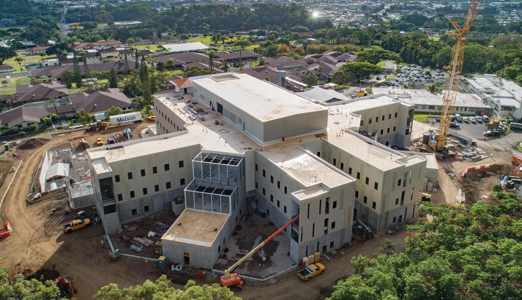
The new facility is nestled in the majestic Ko'olau mountain range.
The $160 million New Patient Facility at the Hawaii State Hospital is a four-story, 144-bed, 196,944-square-foot secured psychiatric facility on an existing psychiatric hospital campus. At the foot of the Ko’olau Mountain Range, this facility includes patient care units, a rehabilitation mall, multiple offi ce spaces, a standalone central utility plant, a separate gymnasium for recreational therapy, and a site elevator with a walkway bridge structure. Due to the ever-increasing patient population and a high percentage of high-risk forensic patients, the existing hospital could not keep up with the demand, and a larger facility was needed. e project was executed using the design-build delivery method led by Hensel Phelps.
Building Description
e 63-foot-tall main building measures 310 feet in the north-south direction and 384 feet in the east-west direction. e building’s footprint is not the typical rectilinear shape. Instead, six patient wings extend out from the center core of the building (Figure 1). e separated patient wings were formed in such a way to provide protection and privacy for select groups such as women, the elderly, and violent patients. e ground fl oor spaces serve various functions, including a chapel, courtroom, library, multiple offi ces, art rooms, kitchen and dining spaces, and a secured outdoor rehabilitation mall. Levels 1 through 3 consist of wings for patient living and multiple offi ce spaces. e design follows the 2006 International Building Code (IBC) with amendments by the City and County of Honolulu. With a building classifi cation of Occupancy Category III, the building is designed for a basic wind speed of 105 mph and a Seismic Design Category C. Due to the building’s irregular shape, a modal response spectrum analysis was performed to determine the seismic loads on the structure.
Structural System
e project site is where an existing hospital building was demolished. e building foundation consists of shallow spread footings on in-situ residual and saprolite soils. Upon excavation, it was discovered that the excavated soil could not achieve the same
strength characteristics of the in-situ material and could not be used as structural fill. Instead, the excavated soil was mixed with crushed concrete to attain the soil bearing capacities required for the loads imparted by the building. The facility must be highly resilient to protect the patients, staff, visitors, and greater community from environmental and man-made threats. Therefore, the primary structure must be capable of resisting forces from earthquakes, hurricanes, and the continuous onslaught of a corrosive tropical environment. In addition, the structure must be of durable construction that minimizes future maintenance but still provides an aesthetically pleasing form. The original concept for the facility utilized load-bearing CMU walls in place of precast concrete walls at the facility’s exterior and all interior stair/elevator cores. Although slightly more costly than CMU, precast concrete walls saved considerable construction time and were the best choice for Hawaii’s remote location. The primary structure consists of load-bearing exterior precast concrete walls and interior precast concrete columns supporting a floor system with precast concrete hollow core planks at typical locations and double tees at heavier loaded areas with longer spans (Figure 2). Precast concrete facilitated construction by allowing portions of the building to be fabricated offsite, then delivered and assembled on-site with minimal interruption due to weather. It also provides an efficient structural system with the strength to support all floor/ roof loading, including the weight of substantial non-load bearing concrete masonry partition walls, and the rigidity to limit deflections and control perceptible vibrations. Furthermore, precast concrete is an inherently durable material detailed to withstand the corrosive tropical environment of Hawaii and ease future maintenance. The building foundation consists of shallow spread footings such as isolated column footings, continuous wall strip footings, and mat footings at elevator cores. The roofs of the mechanical and elevator penthouses consist of a bare metal deck supported by structural steel beams. In contrast, the gymnasium roof consists of a bare metal deck supported by structural steel trusses. The lateral force-resisting system mainly consists of intermediate precast concrete shear walls. The structural diaphragm, which distributes and transfers laterals forces to the shear walls, consists of a 4-inch cast-in-place concrete topping at typical floors and a 3-inch cast-in-place concrete topping over precast framing at roof diaphragms.
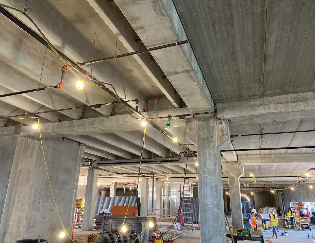
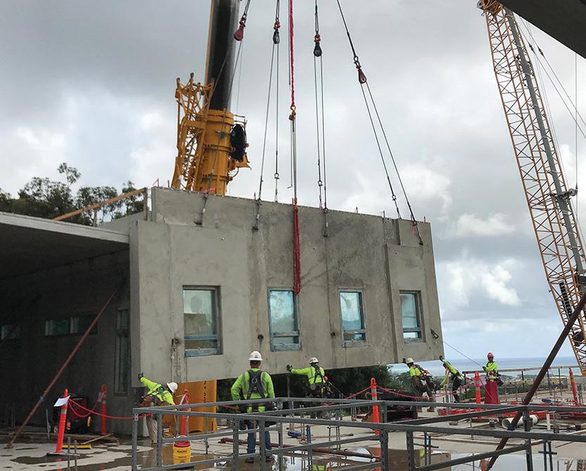
Figure 3. Installation of the precast wall panel with the cast windows.
Constructability and Design Challenges
Located in the city of Kaneohe on the east side of Oahu, the site receives a substantial amount of rain and moisture. On-site CMU construction would have unacceptably delayed the project. The use of precast concrete allowed the project schedule to be maintained and ultimately saved about six months on the schedule. Precast concrete was also the best choice for Hawaii’s remote location. Other gravity load-resisting systems (structural steel and cast-in-place (CIP) concrete) were evaluated for this project, but precast concrete was the optimal choice to meet budgetary and schedule restraints for several reasons. Precast concrete is locally sourced and manufactured, whereas structural steel must be fabricated on the mainland and shipped to Hawaii. Any major field issues during erection are much more difficult and time-consuming to address with structural steel since required materials may not be locally available. The need for fire-proofing was also a drawback for structural steel. The factors mentioned above and potential delays due to shipping made the locally produced precast a more attractive option. Like precast concrete, CIP concrete is locally sourced. However, with the wet and rainy conditions at the site, cast-in-place concrete construction faced schedule issues similar to those with CMU, such as fewer available days for construction. Several structural challenges were efficiently addressed with the use of precast concrete. The Occupancy Category III structure is subjected to moderate to high seismicity, hurricane-force winds, and a corrosive tropical environment. The use of load-bearing precast concrete walls at the exterior of the facility simultaneously addresses these forces and the environmental factors. The intermediate reinforced precast concrete walls are designed as shear walls for resistance to in-plane earthquake (and hurricane) forces. The walls also resist out-of-plane hurricane-force winds and are detailed to withstand Hawaii’s climate with minimal future maintenance. The climate and tropical environment in Hawaii facilitate accelerated corrosion, partly due to the higher amount of chlorides in the atmosphere and the humidity. Several measures were taken to slow down the corrosion rate, such as using hot-dip galvanized steel when exposed to weather or in unconditioned spaces, using zinc-rich paint coating where field welds could not be avoided, and applying multiple coats of elastomeric coatings at exterior faces of the precast concrete walls. In addition, the precast concrete mix used very low w/c ratios (w/c = 0.35) and included fiber reinforcement to help increase the concrete durability. Precast
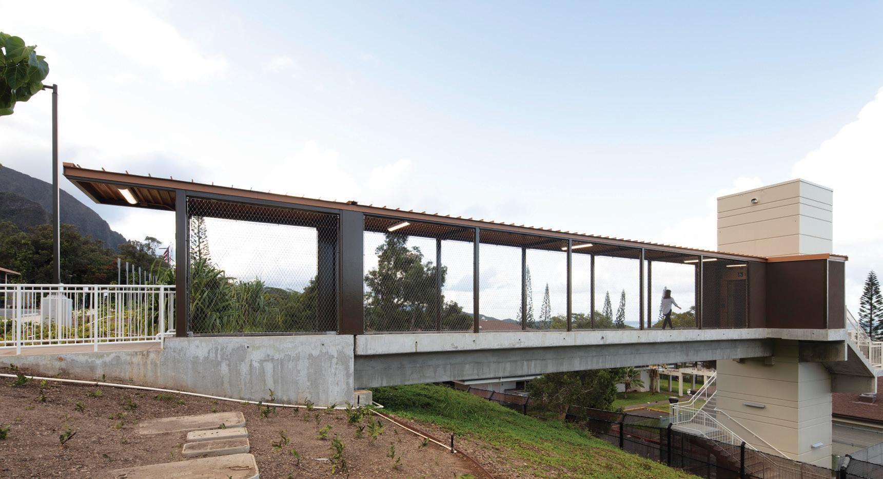
Figure 4. Double tee bridge with site elevator/stair tower.
concrete wall panels were also provided with prestressing strands to help control cracking. Security for patients, staff, and the community is a critical design consideration for a psychiatric hospital. The exterior shell of the facility (i.e., all exterior walls and roofs) had to meet stringent security requirements such as limitations to reinforcement bar spacing as required in the Facility Guidelines Institute’s (FGI) Guidelines for Psychiatric Hospitals and the FGI Design Guide for the Built Environment of Behavioral Health Facilities. Achieving the requirements for vertical enclosures using load-bearing precast concrete wall panels was very efficient. The size and spacing of the reinforcement steel were slightly adjusted to meet the security requirements, but this did not add any appreciable cost to the panels. Precast concrete eliminated the need for thick steel security panels at the exterior of the building, which would be required if non-load bearing lightweight framing was used. Furthermore, the floor system of 8-inch-thick hollow-core precast sections with cast-in-place concrete topping satisfied the security requirements without any additional enhancements. Another design challenge was creating an exterior aesthetic that presents a non-institutional, non-threatening character sensitive to public perceptions and responds to Hawaii’s climate, environment, culture, and customs. The precast concrete wall panels provide visual interest, scale, and delight through various configurations and finishes. Form liners were used on the panels along the main walkway at the front entrance to introduce a Hawaiian Piko pattern. Piko in Hawaiian is another word for the navel where life begins, and the symbol brings new life and purity to the world. It also represents peace, tranquility, spirituality, and a strong sense of regrowth or new beginnings. The intricate repetitive design cast into the precast panels creates a unique Hawaiian sense of place for all those entering the facility. It was crucial that this high-security facility integrate into the architecture of the existing surrounding hospital buildings and that the building’s overall form was sensitive to the neighboring community and displayed a Hawaiian sense of place. The use of precast concrete wall panels with various finishes and reveal patterns accomplished this goal without compromising strength, durability, or security. attention in planning, detailing, and executing the precast fabrication work to protect the glazed window units and circumvent breakage during production, handling, transporting, and erecting the panels (Figure 3, page 31). This novel approach to installing the window units compressed the schedule and allowed the building to be enclosed from the elements much quicker. With the windows cast together with the wall panels, a higher level of quality control than field installation was achievable, enhancing the interface’s quality and durability between windows and walls. In addition, the prefabricated security window assemblies are operable, allowing for natural ventilation while incorporating enhanced security features such as special handles that cannot be used for self-harm and that eliminate the possibility of passing contraband or throwing things from windows. The standalone site elevator/stair tower and bridge structure are simple but unique designs allowing staff and guests to access the new facility from the lower campus levels. The elevator tower consists of stacked precast concrete wall panels forming a core. A 32-inch-deep precast double tee bridge spans from the elevator tower to the upperlevel abutment. The bridge is covered by a lightweight steel canopy supported by the bridge structure. The precast concrete stairs wrap around the elevator tower and are supported using flag walls, concrete wall segments cast with the wall panel that cantilever from the panels. See Figure 4 for the bridge structure and site elevator/stair tower with flag walls. The unique flag wall design eliminated exterior support columns, which would have been difficult to install within the tight footprint, and reduced the cost of the tower.
Conclusion
Through the constant collaboration of the design-build team and the adaptability afforded by the design-build delivery method, the construction of the Hawaii State Hospital New Patient Facility was completed on time and within budget despite the challenges faced. Although not evident initially, the precast option with a higher material cost resulted in an efficient design, saving the project time and other associated costs inherent in concrete properties. It is not always the lowest cost structural system that produces the most efficient and economical design. This also highlights the benefits of the design-build process. Without the Contractor’s input, there would have been significant impacts on the schedule, and structural work may not have gone as smoothly.■
Kevin Galvez is a Senior Structural Engineer at BASE (kgalvez@baseengr.com). Frank K. Humay is Vice President at BASE (fkh@baseengr.com).
Innovations and Accomplishments
This was the first project that the precast manufacturer (GPRM) cast the window frames, including the glazing, into the panels with the concrete pour. In researching other precast producers, this may have been the first time this was done with the glazing already in the frame. This technique required a new and enhanced level of Project Team
Owner: State of Hawaii, Department of Health Structural Engineer of Record: BASE Architect of Record: G70 General Contractor: Hensel Phelps Precast Concrete Supplier: GPRM Prestress
DESIGN
COMPARE
DOCUMENT FOR ANCHORING TO CONCRETE

Building with steel and concrete takes vision, power, and structural design without limits.
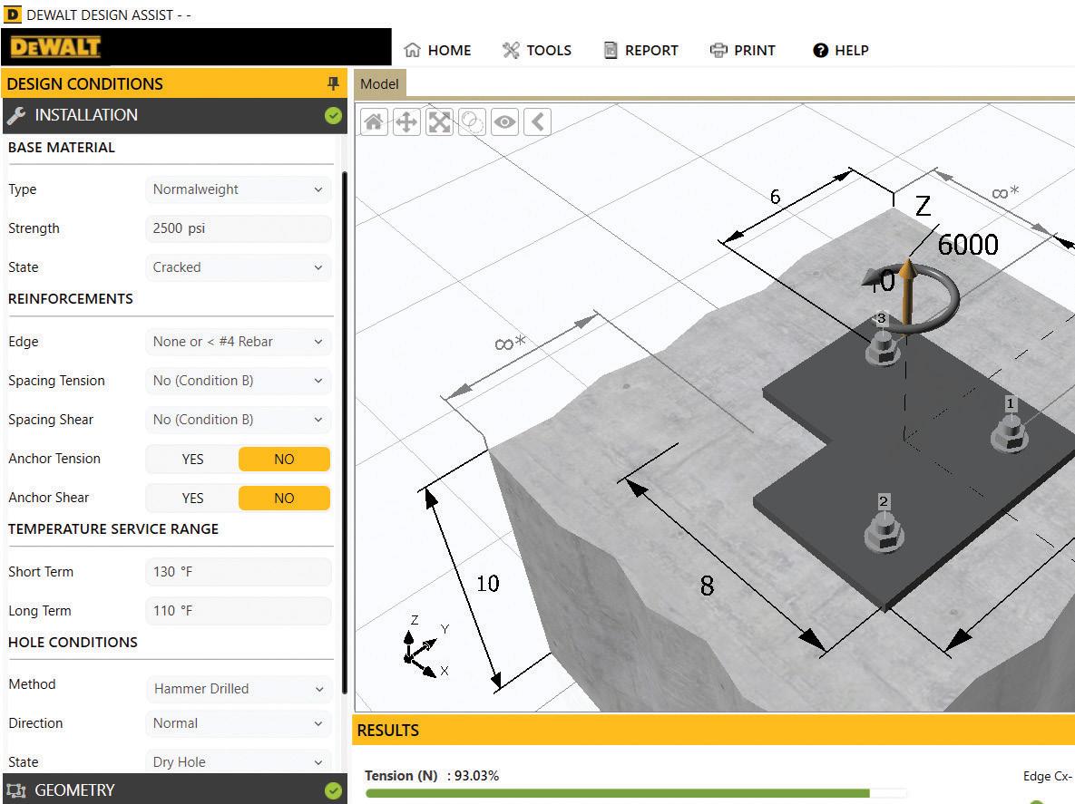
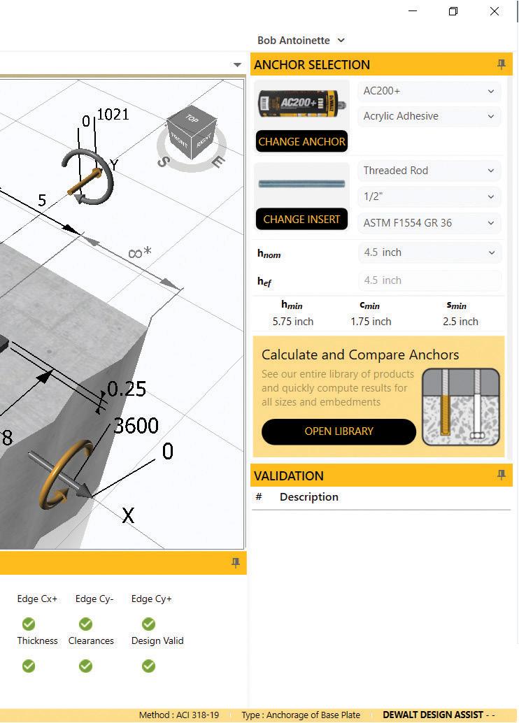
DEWALT DESIGN ASSIST™ (DDA) is a no cost/no fee state-of-the-art structural design software that streamlines, automates, and optimizes your concrete anchoring design process. With multiple design standards to choose from, a comprehensive library of anchors, numerous reporting options, and a wide range of design tools, simplify your design process with DEWALT Design Assist.
ANCHOR TYPES
Cast-in-Place Mechanical Adhesives CODE COMPLIANCES ACI 318-19 ACI 318-14 CSA A23.3-19 CSA A23.3-14
DOWNLOAD THE FULL SUITE FREE AT DEWALT.COM/DDA


FOR ANCHORING TO CONCRETE

FINITE ELEMENT ANALYSIS BASE PLATE
THICKNESS SOLVER
ANCHORS & FASTENERS
KEY FEATURES AND BENEFITS
Base Plate Anchorage
The standard tool to use when considering anchorage to concrete, allows complete geometric flexibility with the anchor patterns or base plate shape. Designs are calculated to be compliant with the latest major published design criteria and use products that have been tested by independent approval bodies for performance.
Equipment Anchorage
Further extending the functionality of base plate designs, you can now leverage this tool to model wind and seismic forces acting on equipment and resolve optimal anchorage solutions at a larger scale.
Anchorage to Deck Members
Into the floor or overhead, this functionality considers the unique designs where anchoring to concrete deck members is required. Various considerations are taken into account for the multiple cast-in or post-installed products DEWALT has to offer.
Base Plate Thickness Solver
Using finite element analysis, this tool discretizes the baseplate into elements to calculate the optimal thickness to determine when the plate is infinitely rigid. A heat map is generated to highlight the distribution of the stresses on the plate. Post-Installed Rebar Design
Enables the design of post-installed rebar doweling using cast-in place design methodology rather than the limit states used in anchor design.
Anchor Comparisons
Comparisons of anchors can occur in several ways within DEWALT Design Assist. For a broad analysis, quickly calculate and filter the entire anchor library with a click of a button. To take a more detailed look, use the Anchor Comparison Tool to easily see differences across anchor types, sizes and brands to intelligently and effectively select the optimal product for your design.
Independently Verified
To provide the best possible design aid DEWALT has partnered with leading engineering firms for the development of the core calculation logic. In addition to extensive internal software testing, various design scenarios were independently validated to ensure accuracy and precision for the most critical designs.
Versatility
Adaptable approach in DDA allows designer to choose between pre-defined or customized load combinations. Advanced interaction of tension and shear forces feature allows designer to choose between trilinear (1.2) option and traditional (5/3) approach.
PRODUCT KNOWLEDGE, TRAINING, CERTIFICATIONS
Anchor Installation
Manufacturer's Training available for all of DEWALT Post Installed and Cast In Place Anchoring solutions. Powder Actuated Tool Training and Certification
In accordance with current OSHA Standards. DEWALT Adhesive Anchor Installer Certification
In accordance with current ACI318 recommendations.
IS PROUD TO BE AN EXHIBITOR AT THE:
