9 minute read
Industry Insights News items about the sulfuric acid and related industries

Sulfur gun advancements
In production of sulfuric acid from molten sulfur, it is critical that the sulfur is atomized into droplets so that combustion occurs efficiently. The spray nozzle converts bulk sulfur into a predictable droplet size distribution, spray angle, and coverage. The most widely used nozzle in sulfuric acid production today is the BA WhirlJet ® nozzle. These nozzles provide superior performance during normal operation, but when flow is decreased or turned off, the nozzles may plug. This happens because the nozzles protrude beyond the steam jacket of the sulfur gun. Without the cooling provided by the steam jacket, the sulfur flowing inside the nozzle heats up beyond the normal working temperature. This causes the sulfur viscosity to increase and plugging may occur.
Operators have been compensating for this by purging the nozzles or removing the guns at the end of operation. However, if one of these actions doesn’t occur quite quickly, pluggage is likely. Flexibility in production rates is required to optimize sulfuric acid production. Sulfur guns are either turned on and off, or flow rate is increased or decreased. To meet this requirement and minimize pluggage, a new sulfur nozzle and gun have been introduced. The CBA SulfurJet™ nozzle has the same superior performance as the BA WhirlJet nozzle. The CBA SulfurJet gun features a steam jacket that fully protects the nozzle to minimize or eliminate plugging. As sulfur passes through the CBA SulfurJet nozzle, sulfur temperature is maintained in the optimal range as production rates change.
Computational Fluid Dynamics (CFD) was used to model heat transfer in a sulfur gun with BA WhirlJet nozzles and a gun equipped with CBA SulfurJet nozzles. A full flow rate condition of 9,410 kg/hr (20,745 lbs/hr) sulfur at 150 psig ΔP (10 bar) was compared to a reduced flow condition of 1,745 kg/hr
Fig. 1
Fig. 3
(3,847 lbs/hr) sulfur at 5 psig ΔP (0.35 bar). The feed sulfur temperature was set at 284°F (140°C) and steam in the steam jacket pipe was at 293°F (145°C) and 60 psig (4.1 bar).
At full flow conditions for both spray nozzles, the sulfur temperature was maintained until it exited the spray nozzles. The temperature change in the BA WhirlJet nozzle was validated when the reduced flow conditions were used.
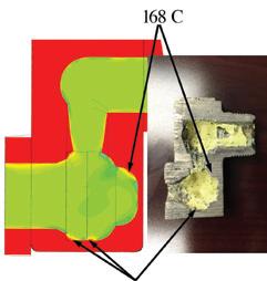
Fig. 1 shows the BA WhirlJet nozzle at the reduced flow conditions. The sulfur polymerizes inside the nozzle as the temperature rises above 305.6°F (152°C) and starts to form a skin. Over time, the skin grows thicker and reaches the point where the sulfur can no longer pass through the nozzle.
The CBA SulfurJet nozzle is shown in Fig. 2. At the same reduced flow condition, the sulfur temperature remains at 289.4°F (143°C) as it passes through the nozzle. Polymerization does not occur.
Due to the hydraulic atomization design, the pressure to the gun is decreased as the flow rate is reduced. As a result, velocity through the internal cavity is decreased. Velocity for the BA
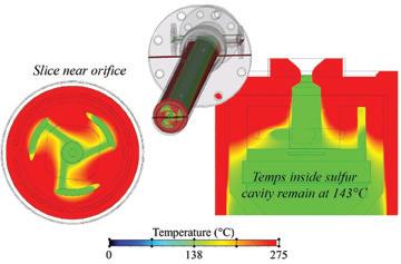
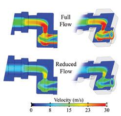
WhirlJet nozzle at the exit is reduced from approximately 32 m/s (105 ft/sec) at full flow rate to approximately 8 m/s (26.2 ft/ sec) at reduced flow rate as shown in Fig. 3. Since the fluid moves more slowly through the gun, the temperature near the walls of the sulfur cavity increases to 635°F (335°C). This causes the sulfur to polymerize at 318.2°F (159°C) and eventually build a skin inside the nozzle. The velocity decrease in the CBA SulfurJet has a smaller impact temperature of 442.4°F (228°C) and pluggage is avoided.
Summary
The new CBA SulfurJet nozzle and CBA SulfurJet gun deliver the flexible performance required by producers. The new nozzle provides superior atomization of bulk sulfur so producers can achieve the same or better performance than the BA WhirlJet spray nozzles currently in use. In addition, the new gun design allows production rates to be adjusted with reduced risk of pluggage. Producers will be able to maximize production time, reduce maintenance time, and extend gun life.
Chuck Munro has more than 20 years of experience in spray technology with Spraying Systems Co. He is a specialist in the petrochemical and chemical industries and is active in several industry committees. For more information, visit www.spray.com. q
The profitable way to sulfuric acid VK sulfuric acid catalysts
Keep conversion rates high and production costs low with the VK range of sulfuric acid catalysts. Partner with Topsoe, as we are the leading supplier of sulfuric acid catalysts, and get holistic solutions for your plant. Our experts assess and deliver tailor-made solutions, maximizing your performance.
By: Steve A. Ziebold, Doug E. Azwell, and Evan Uchaker, DuPont Clean Technologies, MECS ® Sulfuric Acid & Environmental Technologies
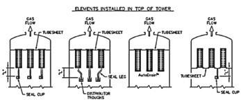
In sulfuric acid absorbing towers, a hanging mist eliminator has traditionally used a drain leg or seal leg directed to distributor troughs or a drain leg/seal cup combination to allow collected mist to drain by gravity out of the element into the process, as shown schematically in Fig. 1. Draining liquid travels from a low pressure point on the gas discharge side of the element to a higher pressure point upstream of the element. The drain leg or drain leg/ seal cup fails when blocked or plugged, which prevents liquid from draining out of the mist eliminator. The drain leg or drain leg/seal cup also fails when blown—when a liquid seal is lost resulting in gas flowing up through the drain leg directly, bypassing the mist eliminator.
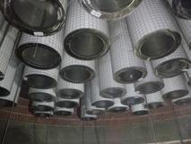
At a plant in South America, a client was having problems with high-drip acid accumulation downstream after their IPAT hanging mist eliminators. Upon entering the tower and inspecting the tubesheet from the top side, one side wall area had excessive sulfate and there was a considerable amount of wet sulfate on the tubesheet. One element was found to have free standing liquid in the bottom as shown in Fig. 2. It was apparent acid had backed up and was trapped in the element since collected liquid was not freely flowing into the center drain coupling. On subsequent inspection under the element, the seal cup was found to be plugged solid with sulfate.
When a hanging element drain is blocked, collected liquid in the bottom of the element rises to the top of the internal gas veil and tries to drain back through the fiberbed against the gas flow. The collecting fibers become over-saturated and gas flowing through the fiberbed creates bubbles at the liquid level/fiberbed interface which in turn generates acid particles by bubble shatter. Acid particles then travel downstream carried by the gas exiting the mist eliminators, exposing downstream equipment to drip acid resulting in corrosion and maintenance issues.
At a plant location in the United States, a client was having spotted stick tests and drip acid accumulation downstream of their hanging IPAT mist eliminators. After plant
shutdown and tower inspection, the root
cause was determined to be a separated
drain leg threaded fitting that became loose
and detached by process vibration. The cli
ent was able to re-attach their threaded drain leg fitting and the downstream stick tests cleared up and drip acid was eliminated. For element drain legs, if threaded fittings are used, it is a prudent practice to tac weld threads to prevent separation during process service.
Like a blocked element drain, a blown element drain is also an operating condition that, if left unchecked, will have serious maintenance consequences. Gas bypassing through a blown element drain leg prevents liquid collecting in the bottom of the element from draining. A large amount of re-entrainment is formed by gas vertically discharging through the bottom
element drain coupling and consequently
shearing collected liquid and regenerating
acid particles (Fig. 3). Acid particles are
then carried downstream by the gas exiting
the mist eliminators, exposing downstream
equipment to drip acid and resulting in cor
rosion and maintenance.
A blown seal leg two inches in diam
eter and three feet long exposed to a 250
mm WC element pressure differential will bypass about 460 ft 3
min -1
of dirty gas with
an upward gas velocity leaving the seal leg at about 350 ft s -1
. At this velocity there is plenty of gas shear force to atomize acid accumulated in the bottom of the element into small particles that re-entrain and discharge from the element resulting in corrosion of downstream equipment.
Fig. 2: Free standing acid at the bottom of an IPA T tubesheet element.
Fig. 3: Schematic representation of a blown seal leg.
New proven alternative to
traditional hanging element drain legs
The patented MECS ®
AutoDrain ™ (AD) option for hanging style Brink ®
mist
eliminators effectively drains acid without
the use of expensive seal legs/seal cups or complex seal leg piping systems (Fig. 4) routed to MECS ®
UniFlo ®
distributors.
AD eliminates the hazard of working in acid resistant apparel required to attach drain legs to hanging elements below the tube sheet, which is a very dangerous work area. When elements are removed from a tower, this same hazardous work must be performed to detach drain legs before they can be lifted out, and AD eliminates this hazard as well.
AD eliminates element seal legs directly routed to trough distributors or seal leg/seal cup assemblies, which are the more frequent maintenance spots in the absorbing tower and one of the more
difficult areas to troubleshoot. Also,
when maintenance is required on tower
acid distributors, the hanging drain legs
(pipes) from the mist eliminators are a significant obstruction to anyone working in acid resistant apparel, which can result
in falls and injury. AD eliminates this
safety hazard by removing all the hanging
drain legs or seal legs/seal cups, providing
significantly fewer obstructions under the
mist eliminators resulting in easier and safer maintenance on tower components.
In fact, when observed through view
ports during operation, the inside plate at the bottom of the element with AutoDrain ™
will typically be dry, while the bottom
plate of a standard element will typically have some accumulated liquid on it. As a result, AutoDrain ™
elements have less en
trainment and higher efficiency than standard elements.
While there have been recent claims of similar devices, these devices are not comparable since they use liquid traps. Liquid traps require liquid height changes to allow collected liquid to drain from the bottom of the mist eliminator when an internal float changes position. The liquid trap is not recommended for sulfuric acid service due to buildup of sulfates on sealing surfaces during operation, leading to premature failure during operation causing re-entrainment. The bottom element plate operates in a fully wetted state and may hold up a larger volume of acid than with standard drain legs. AD does not have this kind of operational concern as the bottom of the element operates bone dry.
While the consequences of improper seal leg and seal cup maintenance and operation have been broadcast throughout the industry, they continue to be a reoccurring problem. It is critical that mist eliminator users stay up to date on maintenance and inspections to mitigate any potential issues so that their mist eliminators achieve satisfactory performance and long service life. For more information, visit http:// www.cleantechnologies.dupont.com. q