2 minute read
Implementation Strategy


Design
Whole image
Advertisement
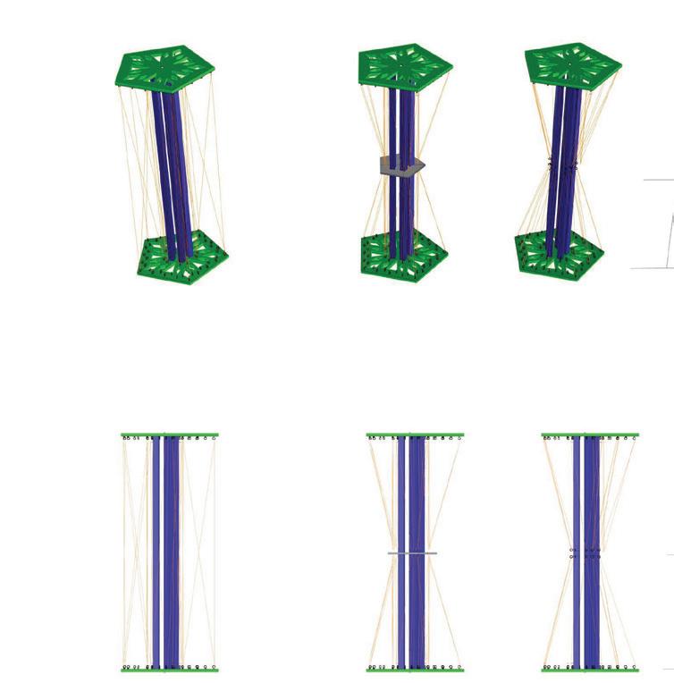
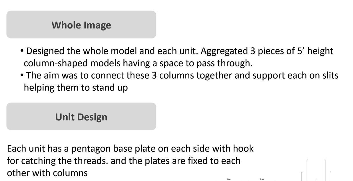
Designed the whole model and each unit. Aggregated 3 pieces of 5’ height column shaped models having a space to pass The aim was to connect these 3 columns together and support each on slits helping them to stand up
Unit Design
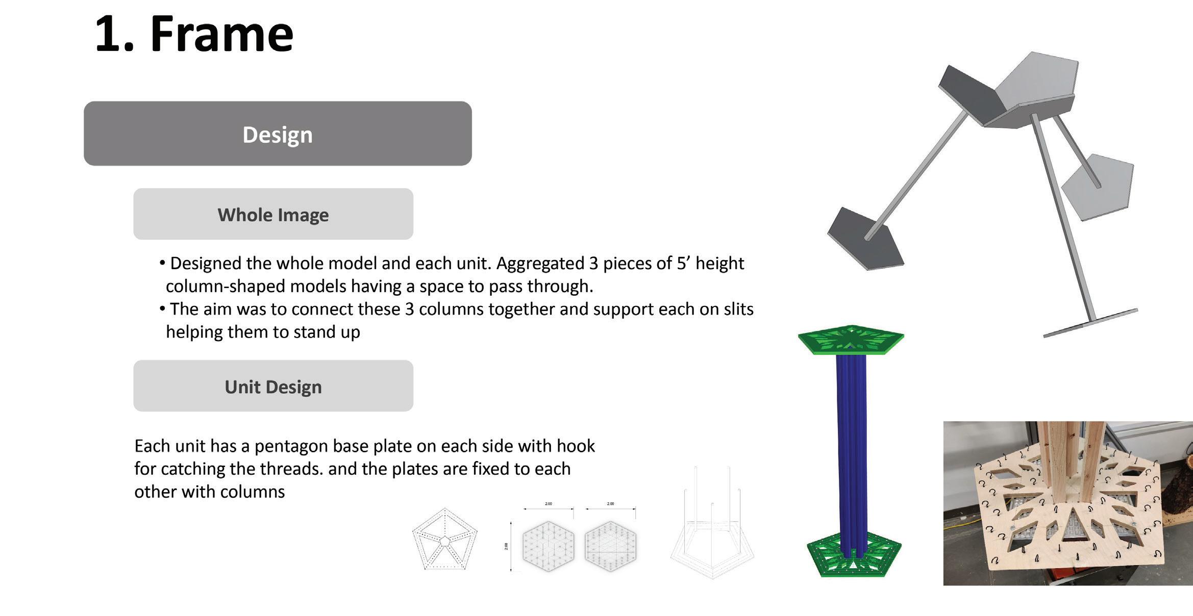
Each unit has pentagon based plate on each side with hook for catching the threads, and the plates are fixed to each other with columns
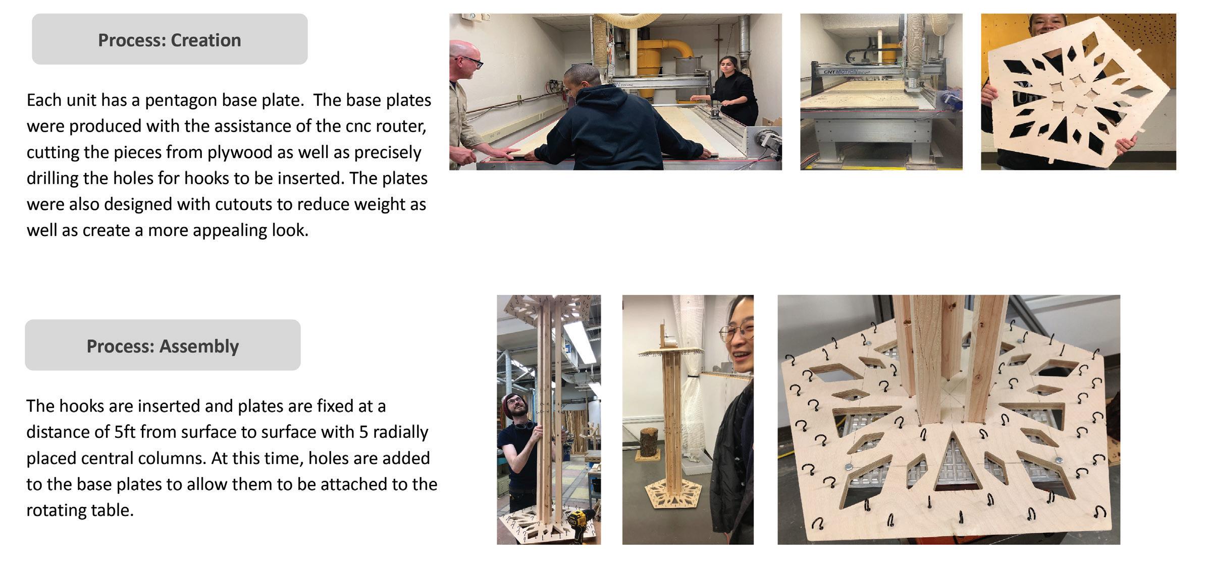
Process Creation
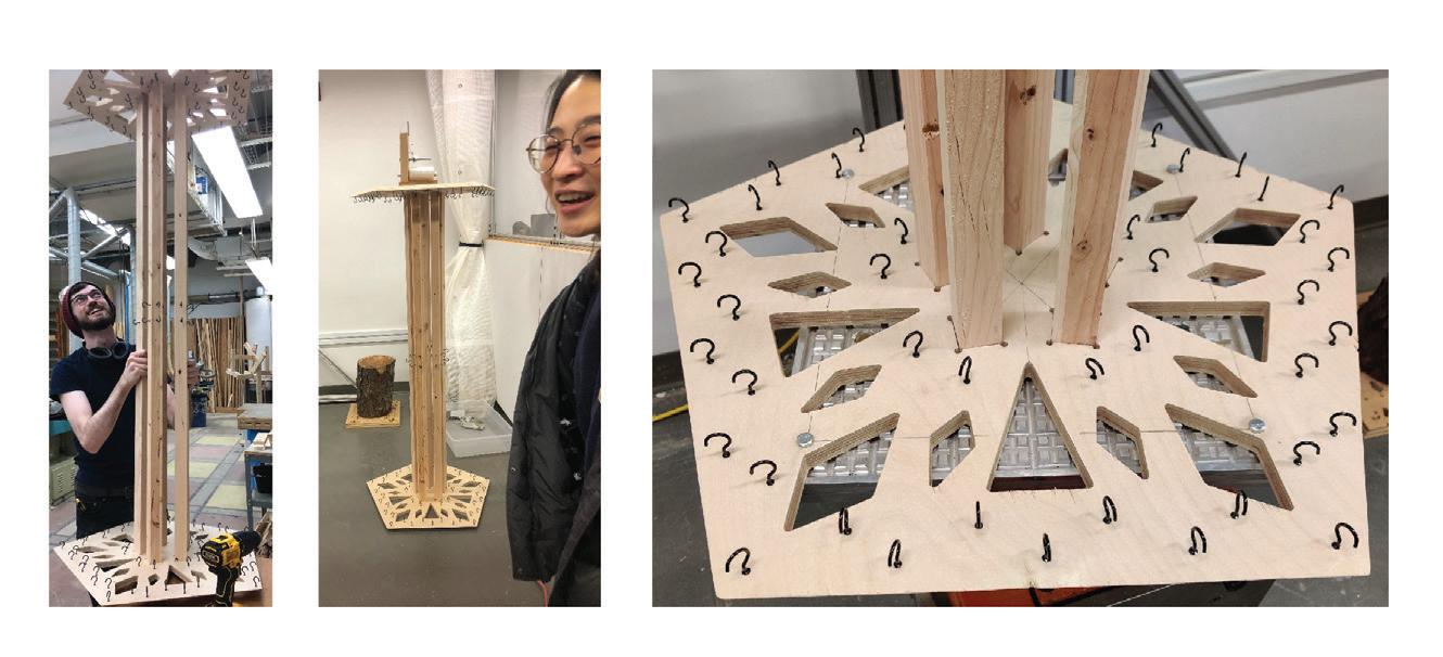
Each unit has a pentagon base plate. The base plates were produced with the assistance of the cnc router, cutting the pieces from plywood as well as precisely drilling the holes for hooks to be inserted The plates were also designed with cutouts to reduce weight as we create a more appealing look.
Process: Assembly
The hooks are inserted and plates are fixed at a distance of 5ft from the surface with 5 radically placed central columns.At this times holes are added to the base plates to allow them to be attached to the rotating table
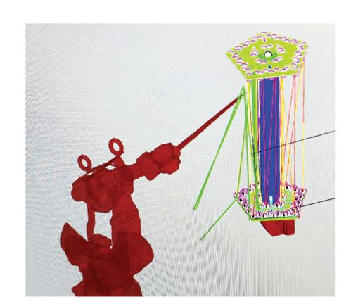
Problem and Solution
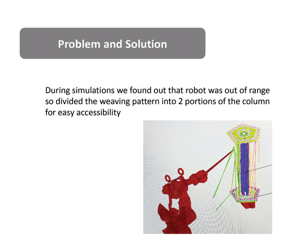
During simulations we found out that robot was out of range so we divided the weaving pattern into 2 portions of the column for easy accesibility
Received suggestions for improvements based on maintaining thread tension and thread feeding
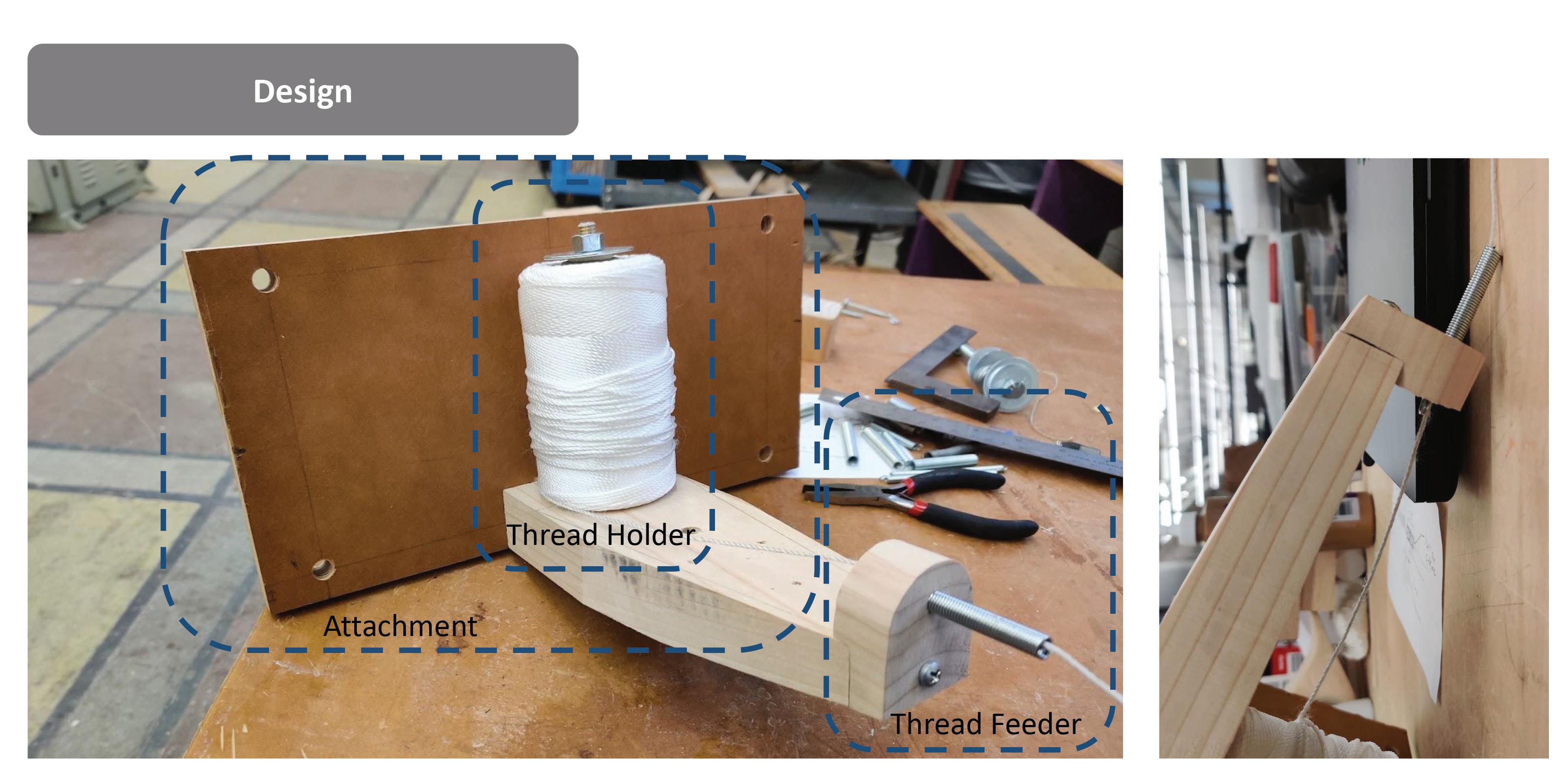
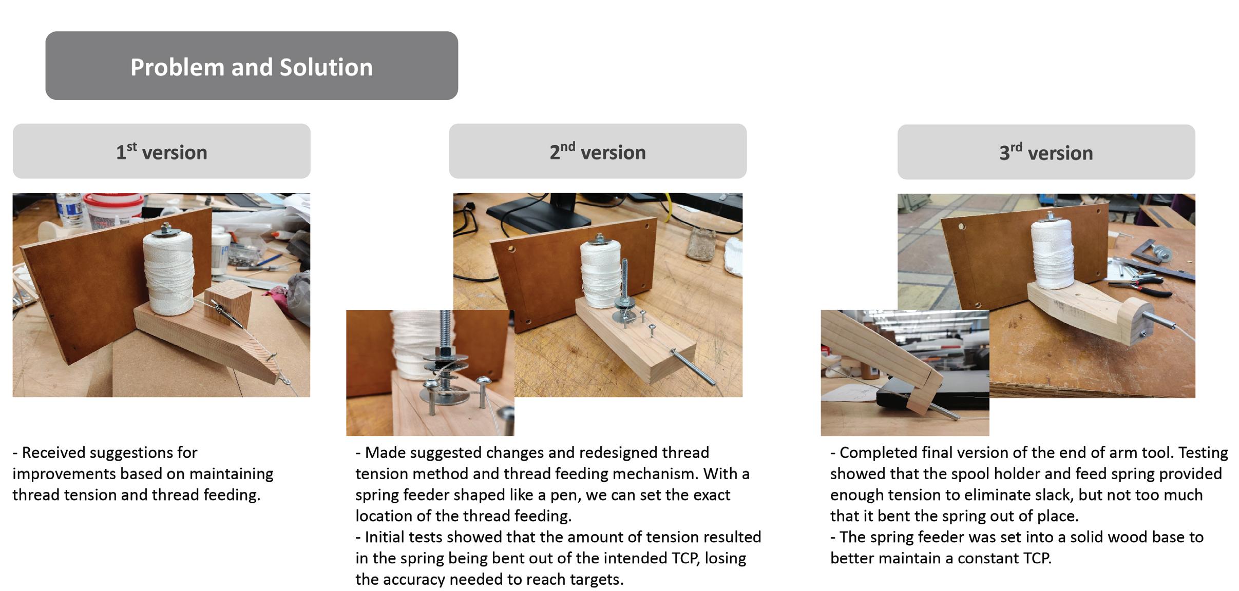
Made suggested changes and redesigned thread tension method and thread feeding mechanusm. With a soring feeder shape like a pen, we can set the exact location of the thread feeding
Initial tests showed that the amount of tension resulted in the spring being bent out of the intended TCP, losing the accuracy to reach the targets.
Completed final version of the end of the arm tool. Tension showed that the spool holder and the feed spring provided enough tension to eliminate slack, but not too much that it bent the spring out of place. The spring feeder was set into a solid wood base to better maintain a constant TCP.
Method
Proper Tension
Connecting hooks to a long distance (vertical connection: farthest)
Undisturbed path
From inner hook to outer hook
Problem and solution
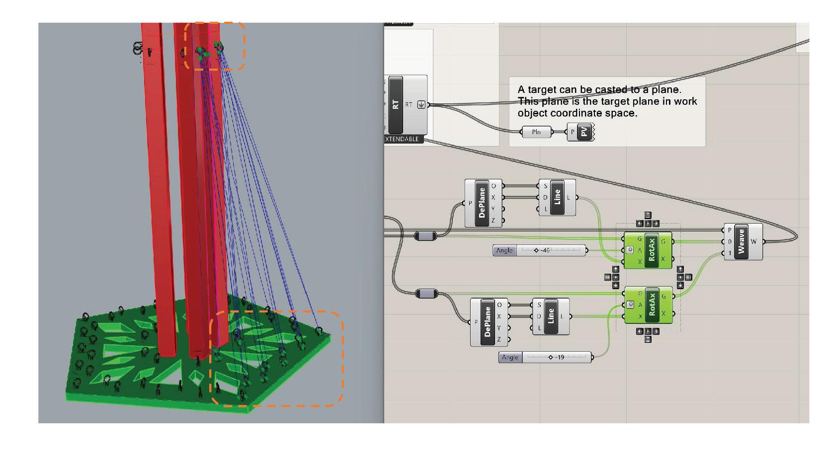
Singularity
Weaving target points were very close to the robot and it would result in singularity in order to reach them so points were separated in 2 groups and their direction of planes were shifted and altered according to requirement
Exact Position
Digital model and physical model have a slightly different dimension in cutting process. Even though we measured physical model and several points, it was hard to set exact location of the path. We completed it with human-robot collaboration. The hooks can be chnaged in direction manually to adjust for robotic simulation paths
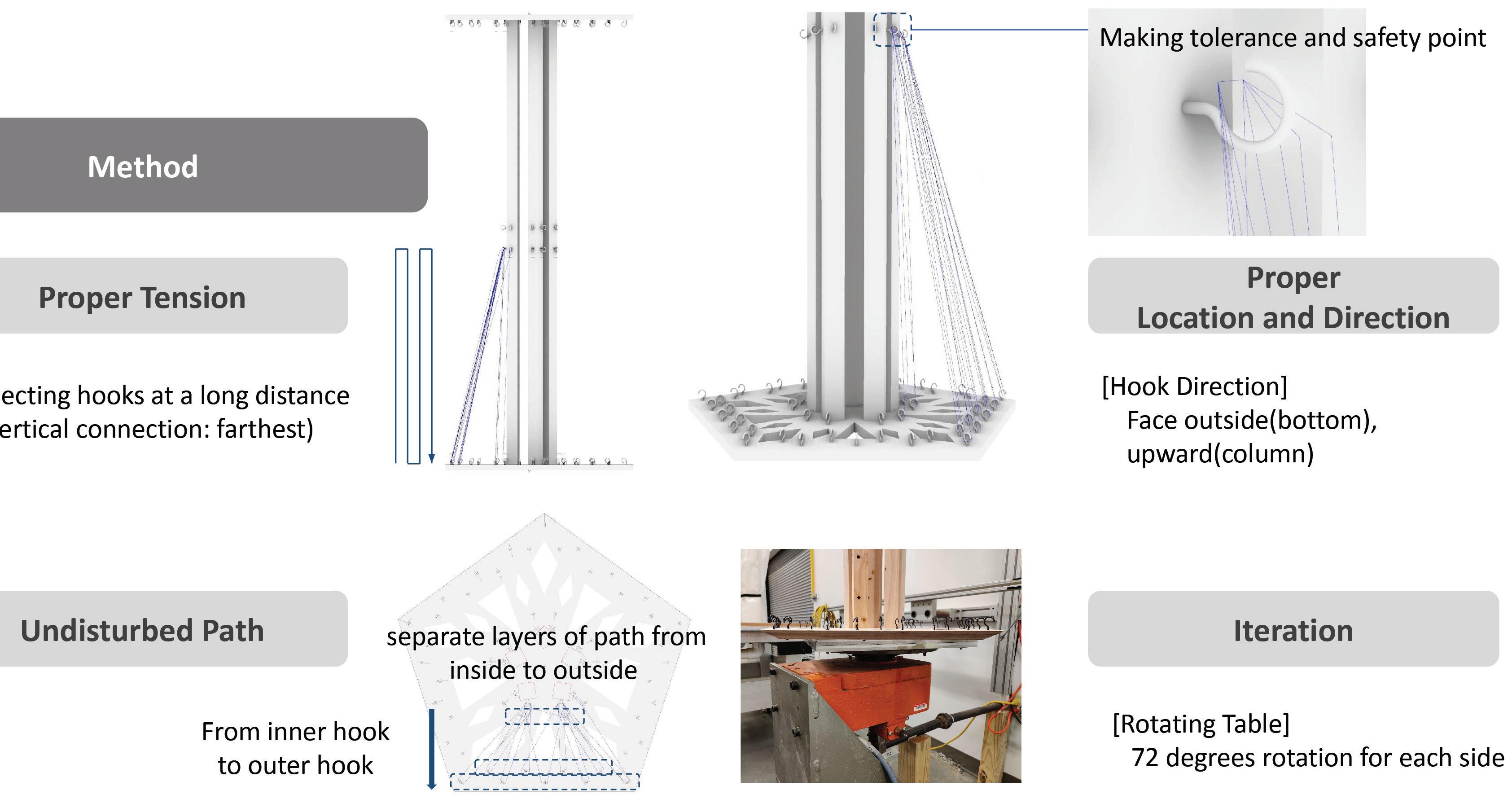
Proper location and Direction
[Hook Direction], Face outside(bottom), upward(column)
Iteration
[Rotating Table], 72 degrees rotation for each side
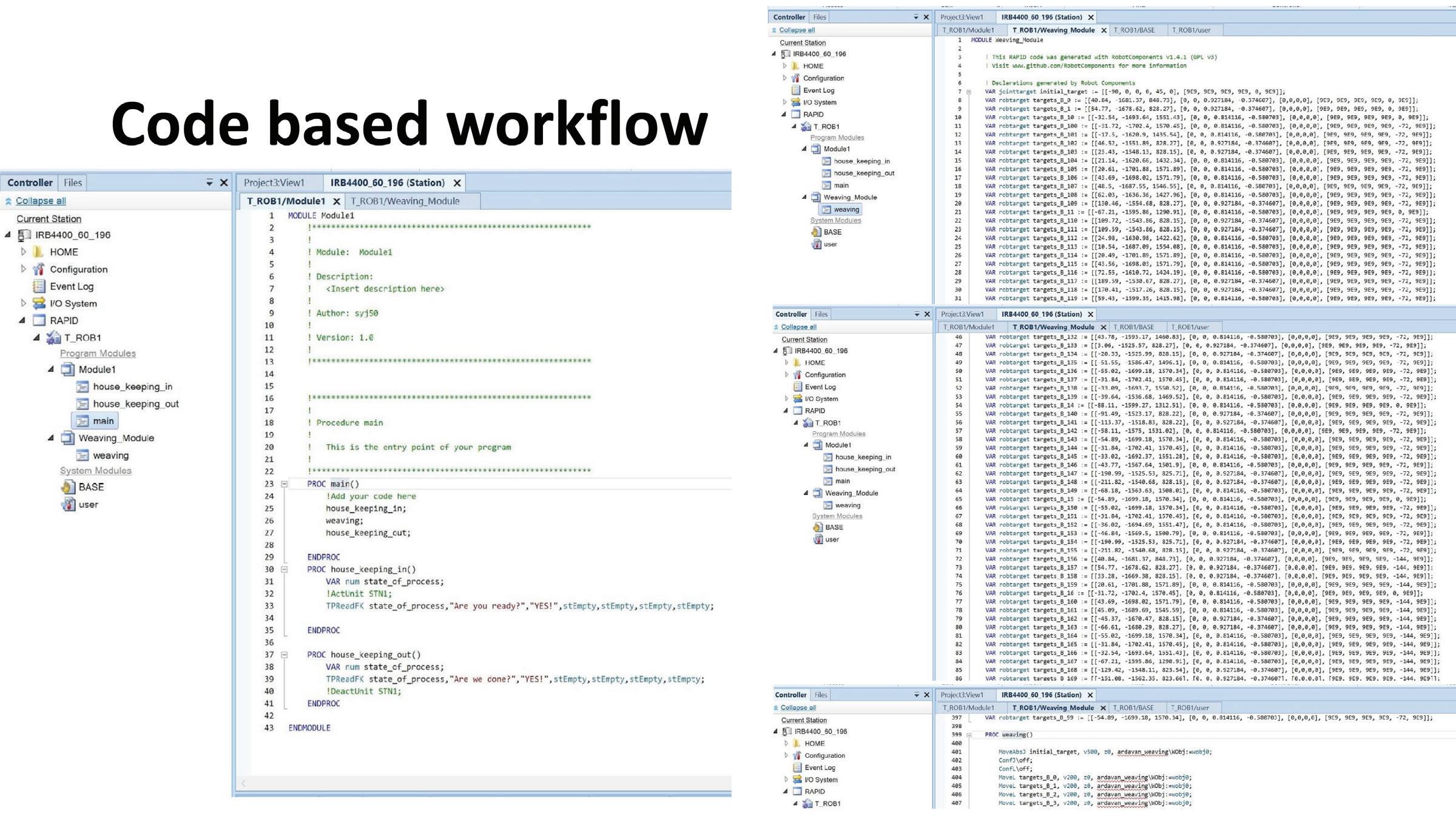
Code Based Workflows

Challenges and next steps
Tool rigidity and ensuring that it did not hit the frameor hooks. Getting the angles just right so the robot arm doesnot hit the frame and lead to singularity errors. Reconciling digital model and codes with the irregularities of the physical frame.
The next steps include refining the robot movement to have even more precision, as well as constructing more frames in order to link them together into an occupiable soft structure.