20 minute read
S wRI DELIVERS NEXT-GENERATION SPACE INSTRUMENT


SwRI delivered a groundbreaking new mass spectrometer for integration onto NASA’s Europa Clipper spacecraft. Scheduled to launch in 2024 and arrive in the Jovian system by 2030, the spacecraft will conduct a detailed science investigation of the moon Europa and study whether it could harbor conditions suitable for life.
The MAss Spectrometer for Planetary EXploration (MASPEX) instrument is one of nine science instruments in the mission payload, which also includes Europa-UVS, an SwRI-developed Ultraviolet Spectrograph, the latest in a series of UV instruments. MASPEX will analyze the gases near Europa to understand the chemistry of Europa’s surface, atmosphere and suspected subsurface ocean. MASPEX will study how Jupiter’s radiation alters Europa’s surface compounds and how its icy surface and subsurface ocean exchange material.
“MASPEX has a mass resolution hundreds of times finer than anything that has flown to space before,” said SwRI Senior Vice President Jim Burch, who serves as MASPEX principal investigator. Burch leads the Institute’s Space Sector, with three divisions devoted to space science, solar system science and space systems. “SwRI has used internal funding and NASA resources to develop an instrument able to differentiate between molecules with almost identical masses based on the energy binding the atoms. It also differentiates isotopes — atoms with equal numbers of protons but a different number of neutrons. These capabilities are critical to revealing the secrets of Europa.”
Once it arrives, Europa Clipper will orbit Jupiter and perform repeated close flybys of the icy moon. MASPEX works by taking in gas molecules lofted from the surface of Europa and converting them into charged particles called ions. It bounces the ions (atoms and molecules missing an electron) up to 400 times back and forth within the instrument. By timing their transit through the instrument, MASPEX measures the mass of these ions, which reveals each molecule’s identity, which in turn will help determine whether Europa is habitable.
“We hope to identify and fly through plumes and other sources of gas venting from cracks in Europa’s icy surface,” said SwRI’s Dr. Christopher Glein, MASPEX co-investigator and a planetary geochemist. “We know microbes on Earth exploit any molecule that can serve as a food source. MASPEX is going to help Europa Clipper determine whether there is anything for microbes to eat, such as organic molecules that might be sourced from hydrothermal vents at the bottom of a deep ocean. The data from this exciting mission will give us a much richer perspective on the habitability of Europa.”
The Space Science and Space Systems Divisions developed a groundbreaking new mass spectrometer for NASA’s Europa Clipper mission to study the potential habitability of Jupiter’s moon Europa. The MAss Spectrometer for Planetary EXploration (MASPEX) instrument has a mass resolution hundreds of times finer than anything that has flown to space before.
1980 Canadian Navy since 300+
For more than 70 years, SwRI has worked in the Communications Electronic Support Measures (CESM) arena. Using signals intelligence, antennas and software, SwRI helps U.S. and allied militaries gather communications intelligence and develop electromagnetic techniques to thwart adversarial operations. CESM specialists develop electronic warfare techniques and technology to control the electromagnetic spectrum and deny advantages to an opponent, while ensuring friendly dominance of the spectrum. Around the world, SwRI specializes in gathering intelligence to identify signals of military interest and to detect, intercept, identify, locate, record and/or analyze the RF spectrum for immediate threat recognition or longer-term operational planning.

1951 U.S.Navy since
>200 maritime applications


by Patrick Siemsen
By the onset of World War II, militaries around the world depended on radio signal transmissions to communicate with their forces, particularly air and naval assets. Nearly simultaneously, militaries began monitoring the communications of combatants, sometimes to great advantage, playing a key role in World War II’s Battle of the Atlantic. Determining the direction of arrival of enemy combatant communications helped pinpoint their actual location. Direction finding, or DF, was directly or indirectly responsible for 24% of all U-boats sunk by Allied Forces during the war.

ABOUT THE AUTHOR:
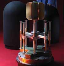
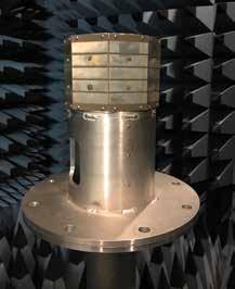
Patrick Siemsen, shown with the cylindrical continuous-slot antenna array being tested atop a 70-foot tower at SwRI’s 200-acre antenna test range, has been developing innovative directionfinding (DF) antenna arrays to support tactical communications intelligence at Southwest Research Institute for over 28 years. He has led the development of a variety of novel DF antennas, among them a body-worn DF antenna vest, a portable DF “tent” antenna and a low-profile, vehicle-mounted distributed DF antenna array. He has also developed low Radar Cross Section (RCS) antennas using conductive composite technology.
Modern-day DF systems are used not only to determine the directions of enemy combatants, but also to locate emergency transponders for search and rescue as well as for situational awareness. By combining the directional information from two or more suitably spaced DF systems, the location of the transmitter can be calculated by triangulation. A key component of naval direction-finding systems is the DF antenna. It consists of one or more arrays of antennas, or elements, and for higher frequencies is distributed around a central mast. The other key component is the processing equipment, which consists of high-end radio receivers and computers.
Southwest Research Institute was founded just after WWII, and some of the very first internally funded research programs advanced antenna technologies. In the 75 years since, the radio spectrum has become exponentially more crowded, jammed with every conceivable wireless signal, pushing operating frequencies higher and higher. What began in the high-frequency (HF) band during WWII has grown to now include veryhigh-frequency (VHF), ultra-high-frequency (UHF) and the lower ranges of the super-high-frequency (SHF) bands. SwRI has developed an extensive communications electronic support measures program and is continually looking for novel solutions in this technical arena to pinpoint the source of increasingly sophisticated signals (see infographic on page 14).
Today’s radio signals are increasingly higher in frequency and bandwidth with complex modulations. It is in this environment that a client asked SwRI to extend the upper frequency range of one of its current shipboard DF antenna systems. SwRI had originally designed, fabricated and installed these systems in the 1980s and supported numerous upgrades to them over the years.
Antennas 101
Antennas are transducers that capture arriving radio signals from the air and convert them into electrical signals at its feed, or connection point. The signals are then sent to processing equipment. Conversely, a radio transmitter generates an electrical signal and sends it via an antenna, which converts it into a transmitted radio signal. Radio signals are electromagnetic waves, a combination of magnetic and electric fields that oscillate at a specific
Radio signals, or electromagnetic waves, consist of electric and magnetic fields oscillating together at a specific frequency. A cycle is the pattern of a wave before it repeats itself, while its wavelength is the distance it travels in one cycle. The number of cycles, or times that a wave repeats in a second, is its frequency, which is measured in hertz (Hz). Kilohertz (kHz) is thousands of hertz, megahertz (MHz) is millions, and gigahertz
Detail
A transducer is an electronic device that converts energy from one form into another. Antennas are transducers that capture radio signals out of the air and convert them into electrical signals.
(GHz) is the billions range. The electromagnetic spectrum ranges from 3 kilohertz up to 3,000 gigahertz. Radio signals are generated by a transmitter and detected by a receiver. An antenna allows a radio transmitter to send radio signals across the airwaves and a receiver to analyze these signals. Transmitters and receivers are typically designed to operate over a limited range of frequencies.
frequency, traveling at the speed of light. In an imperfect analogy, radio signals are like waves on a pond emanating out when a stone is dropped, weakening over distance. The distance between peaks or valleys in the wave is the wavelength. The higher the frequency of the radio signal, the smaller the wavelength. Antennas scale to the size of the wavelength, becoming smaller at higher frequencies. Antennas come in many sizes and shapes depending on their intended operating frequency and usage, which can range from shipboard applications to stationary land installments to mobile body-worn systems.
In a DF antenna array, the antenna elements are arranged to capture an incoming radio signal at various spatial locations to ultimately determine the direction of arrival. Depending on frequency, traditional DF antenna elements are usually of the dipole or spiral type, which respond to the electric field, or the loop type, which respond to the magnetic field. They are usually oriented for vertical polarization, which refers to the direction of the electric field portion of the electromagnetic wave; most radio signals used for communications are vertically polarized.
LOCATION, LOCATION, LOCATION
Most higher-frequency wireless communications today range from 100 MHz to 10 GHz, requiring a direct line of sight from one antenna to another to establish a link. Due to the curvature of the Earth, the range of a radio signal is proportional to the height of an antenna above ground. On a ship, the ideal location for any antenna is the very top of the mast. From that vantage point, an antenna has the best reception and a clear unobstructed 360° omnidirectional view. As one can imagine, this real estate is very valuable on the high seas.
Typically, VHF/UHF DF antennas serve as an extension to the mast of the ship, allowing other antennas of higher priority, i.e. navigational and threat-warning capabilities, to be mounted above them. DF antennas include a central mast with elements extended out around it. The higher the frequency of the radio signal, the smaller the wavelength and the closer the element spacing must be to prevent undesired “ripples” in the beamformed antenna patterns, which are the combination of two or more element outputs. These ripples degrade DF performance and reduce sensitivity. Above a certain frequency, this proper electromagnetic spacing is difficult to maintain using traditional DF elements given their physical build and the required diameter of the central mast. In addition, traditional elements experience destructive mutual coupling in their outputs when spaced too close together. When the client asked SwRI to retrofit an existing antenna to extend its upper operating frequency range into the SHF band, the engineering team at first thought it could not be done without a complete redesign of its mast. With no obvious solutions to the problem, the team had to think outside the box.
A literature search unearthed an unorthodox concept for a wide-band antenna array design originally conceived by Harold Wheeler in 1948, which until now was largely theoretical due to

Detail
Beamforming technology combines two or more antenna element outputs for a given purpose. For example, traditional DF antenna elements beamform outputs to create the “sine” and “cosine” patterns used to determine direction. In next-generation smart antennas, beamforming is used to “steer” radio signals in a specific direction, as opposed to broadcasting in all directions.
Detail
A slot antenna is the complement to the dipole antenna. If a dipole antenna is cut out of a conducting sheet, the remaining material makes a slot antenna, fed across the center.
practical limitations. In this concept, an infinite two-dimensional array of electrically small dipole elements spaced close to each other would offer beneficial mutual coupling and, as a result, achieve wide-band operational performance from the lowest frequencies to the highest. Upper frequency cutoff is based on how closely spaced the elements are. Such an array of closely spaced elements could conceivably solve the ripple problem, eliminating pattern distortion in a circular array. But how to reduce the idea of an infinite array to a practical solution seemed elusive. Different methods described in the literature proved impractical.
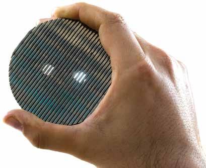
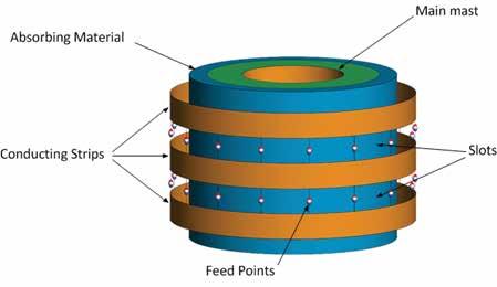
However, one method found in the literature caught the team’s attention: using slot elements in place of dipole elements in Wheeler’s theory. A slot antenna is complementary to a dipole antenna and in its simplest form is just a narrow slot cut out of a conducting sheet and fed from the center. The slots are horizontally oriented for vertically polarized signals, opposite a dipole. Merging electrically small slot antennas long ways, connected end to end, creates a continuous cylindrical slot but with many closely spaced feed points. Multiple slots could then be layered on top of each other. The final product would consist of a cylindrical stack of conductive rings spaced to form slots in between. This design would solve the infinite dimension problem in one dimension but still leave the other dimension and the seemingly insurmountable task of an extremely large number of feeds.
The team was nevertheless intrigued by the idea and set out to model such an array using computer-aided design and electromagnetic numerical modeling software. Eventually the team developed an arrangement that achieved the desired frequency bandwidth while requiring only two adjacent continuous slots in the model to be fed. Additional slots above and below were necessary for electrical loading purposes but did not require feeds. Electromagnetic absorbing material placed inside the slots prevents electrical interactions with the antenna mast.
To feed the two slots, the team devised a symmetrical dual-ring corporate feed network using microstrips on the backside of the conductive rings, providing a uniform distribution of up to eight feeds for a single input. This effectively divided the array into sections, or equally spaced DF elements. Each DF element, including its microstrip feeds, could be fabricated on a single printed-circuit board. The array would be fed by a network of 180-degree hybrids — one for each DF element. Individual antenna elements could be constructed separately and then be assembled around an existing mast in a pie-like manner.
The team obtained internal funding to further refine this design, which they referred to as the cylindrical continuous-slot antenna array, and build a proof-of-concept prototype. This prototype was simple in nature, octagonal in shape and had eight flat antenna sides, or DF elements, with 64 total antenna feeds. Any final version would be curved to create cylindrical appearance. Each element was fabricated using 3D printing technology. From this prototype, SwRI validated the numerical modeling and conducted performance analysis, collecting antenna patterns inside an anechoic chamber. Successful validation and encouraging performance gave the team confidence in further electromagnetic numerical modeling to design the final antenna version for the client and apply for a patent.
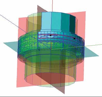
Using computer-aided design and electromagnetic numerical modeling software, SwRI was able to successfully design and predict the performance of the cylindrical slot antenna array before the first piece of metal was cut.
SwRI prototyped the initial design and evaluated its performance in an anechoic chamber and through computer modeling.
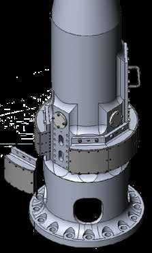
As the team initiated the final version, they wondered if the array could be designed to mount in an abandoned location in the lower portion of the existing antenna mast. The DF antenna had already been retrofitted once, removing a lower frequency array from the bottom half of the antenna mast, leaving behind a series of sealed bolt holes. It was initially assumed the upper portion of the mast would have to be redesigned to accommodate the new array. Taking advantage of this unused real estate at the bottom portion of a mast would eliminate the need for a complete redesign of the entire upper half of the antenna. A mast redesign would have been an expensive endeavor, considering all the design, fabrication and testing involved.
Because the bottom portion of a mast is wider in diameter, the number of antenna feeds would have to increase significantly, a rather intimidating endeavor. However, the successful numerical modeling after the prototype validation allowed the design to move forward without a hitch. The final version consisted of eight antenna elements that individually mated to the existing bolt-hole pattern on the antenna mast. The elements came together like a puzzle, creating the appearance of one continuous curved antenna around the mast with 128 total antenna feeds. The resulting antenna patterns and DF performance were exceptional, solving the ripple problem that plagued previous higher-frequency designs.
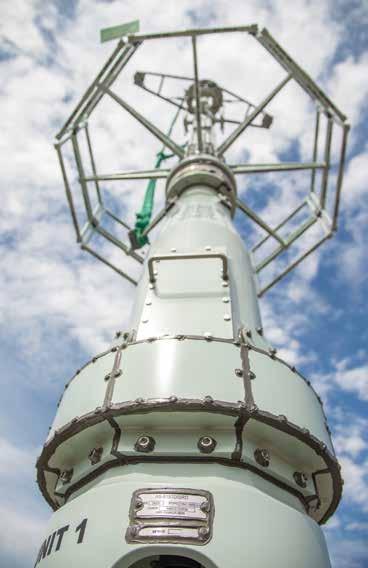
The first retrofitted antenna with the new array was deployed late last year with positive results. Currently, SwRI is under contract to retrofit additional ships over the next several years. In addition to the antenna, the team is updating the below-deck processing equipment with wider bandwidth receivers and next-generation processing capabilities, using SwRI’s Frontier software architecture. The client also plans to provide these advanced capabilities to its next generation of warships.
As this novel antenna illustrates, SwRI remains on the vanguard in developing the latest state-of-the-art antenna technology. Moving forward, the SwRI team plans to utilize a version of this patented slot array in future higher-frequency designs. Other applications of the slot array are under investigation, including airborne and land-based systems. Its lightweight conformal design could also support clandestine law enforcement operations. SwRI is also exploring dual-polarized versions as a research initiative and a reduced-channel version using innovative beamformer combinations for N-channel DF and advanced DF processing with antenna steering algorithms.
Questions about this story? Contact Siemsen at patrick.siemsen@swri.org or (210) 522-2995.
For the final design, the elements individually mated to the bolt-hole pattern on the existing antenna mast abandoned after a previous retrofit. The elements came together seamlessly, creating the appearance of a continuous, conformal antenna. Radomes covered each element for environmental protection.
Optimizing performance through digital twin technology

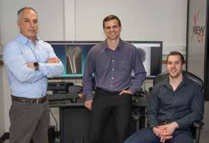
By Daniel Nicolella, Ph.D., Lance Frazer, Ph.D., and Ty Templin
Digital twins are not just facsimiles of their physical counterparts in terms of their geometry or function. Digital twins are immersive virtual models driven by both data and algorithms, which give decision-makers in the physical world access to the nearly infinite exploratory space of the digital world. Advances in digital twin technology follow multiple innovations in engineering coalescing with an exponential boom in modern technologies. These innovations — including smart sensors, machine learning, high-throughput computing, data analytics and advanced simulation capabilities — enable digital twins to dynamically link the digital and physical world. The technology can be used to understand the past with historical data, the present with real-time data and the future with simulations. While testing in the physical world is limited by time, cost, material availability, testing feasibility, etc., digital models are limited only by the data available and computing resources. And smart-sensor technology and other innovative methods are steadily improving data collection while computing power and efficiency continue their exponential growth. Digital twin technology has helped drive the latest phase of the Industrial Revolution, referred to as Industry 4.0.
An exciting and promising application uses digital twin concepts to develop detailed, high-fidelity, physics-based digital twins of the human body. Using a digital representation of a human body, engineers can simulate how the body responds to highly dangerous situations that would be impossible to replicate with live subjects. For example, the technology could characterize how a body would physically respond when faced with a potentially dangerous situation, such as a car crash or pilot ejection from an aircraft. With valid simulations of the physical response of the human body, designers and engineers can improve systems to reduce injuries.
Southwest Research Institute has been developing and applying advanced, high-fidelity digital models of the human body for over 30 years to better understand the risk of injury under extreme conditions, design medical devices and understand how musculoskeletal diseases develop and progress. These digital twins uncover mechanical signals that drive biological tissue adaptation, allowing engineers to optimize protective equipment and safety systems and inform medical advances to ultimately optimize the performance of the human system.
Human Digital Twin
The human body is a highly complex, sophisticated system. In some respects, it is a typical engineering structure required to resist external loads without failure and protect vital internal organs. This viewpoint allows engineers to apply standard, mature, engineering modeling and simulation techniques to understand how the structure will respond to external and internal forces. Early applications of human body modeling and simulation used medical images such as CT or MRI scans from a single individual selected to represent an average individual for the population. SwRI and other researchers around the country and the world have used these models with great success in applications ranging from predicting injury in a car crash to designing joint replacements to understanding cardiovascular disease development. While these early models and applications were highly successful, they represent how a single, average individual may respond and do not account for considerable variability within and between populations. Every human is unique, and differences in anatomical size and shape can have a substantial effect on how the body responds to an external load.
SwRI has developed a suite of advanced modeling and simulation techniques for human digital twins. Advanced uncertainty quantification methods address the variability and uncertainty in biological tissue mechanical properties and responses. Additional techniques efficiently describe the diversity in anatomical structures by parameters such as size, shape and material variation within a group. This variability is directly quantified from medical image databases representing real population-level variability.
In addition, biological materials making up anatomical structures are highly complex and vary between individuals. For example, bones are externally rigid, fluid-filled composite materials that have different physical properties when measured in different directions. Their shape and density change based on loading. The soft tissues that connect skeletal tissues are fluid-filled composite polymers exhibiting a range of properties. Furthermore, the shapes of human anatomical structures are highly complex and cannot be accurately described using traditional design and analysis concepts, such as straight lines, analytical curvatures, and so on. Finally, no two human bodies are the same. From the overall size and shape down to the mechanical behavior of individual tissues, a tremendous amount of variability exists between individuals and within groups, for example, males and females. To complicate things further, the human system changes and adapts over time in response to external forces, disease and aging.
To address these challenges, the Institute has developed, adopted and implemented a suite of advanced modeling and simulation techniques. First, advanced uncertainty quantification methods address the variability and uncertainty in the mechanical properties and responses of biological tissue. The technique treats important tissue properties such as the strength of bone tissue or the stiffness of a ligament as random variables, using values derived from experimental data to characterize how uncertainty and variability affect model predictions, such as injury risk. When the properties of a specific biological tissue such as bone are fairly well characterized, engineers calculate how the variability affects model predictions to help design robust safety systems for the target population. When physical properties of biological tissues or structures are not well enough understood for accurate model predictions, SwRI determines how sensitive our model predictions, say for risk of injury, are to this uncertainty. This sensitivity information is used to better direct resources to improve the understanding of the tissues that most significantly affect model predictions.
Second, advanced techniques efficiently describe the diversity in anatomical structures by parameters such as size, shape and material variation within a group. This variability is directly quantified from medical image databases representing real population-level differences. Treating parameters in human anatomy as random variables better characterizes how morphological differences affect predictions. Using this technique, SwRI designs systems to robustly protect diverse populations from injury rather than protecting the average individual. Individual differences in anatomical morphology can significantly affect a person’s injury risk or chance of developing a debilitating disease. For example, the size, shape and properties of bone tissue within an individual’s femur will significantly affect their risk of fracturing their hip. Similarly, we showed that shape of the bones in the knee joint significantly affects the risk of developing arthritis. For the military, the models show how the shape of the bones in the lower leg can contribute to bone fractures associated with under-vehicle blast loading, such as those caused by improvised explosive devices or IEDs.
Cyber Soldier
The U.S. Navy funded the Incapacitation Prediction for Readiness in Expeditionary Domains: an Integrated Computational Tool (I-PREDICT) program to apply these techniques to create a digital twin of a warfighter. SwRI is working with Elemance LLC, the Medical College of Wisconsin, Duke University and the
SwRI is working with Elemance LLC, the Medical College of Wisconsin, Duke University and the University of Virginia to develop, verify and validate a warfighter digital twin to predict the risk of injury and functional degradation associated with battleground experiences.
University of Virginia to develop, verify and validate a computational human body model to predict the risk of injury and functional degradation associated with battleground experiences. The validated I-PREDICT digital twin will guide mitigation strategies for both highly dynamic and long-duration, chronic exposures, which are difficult to replicate experimentally. I-PREDICT digital twin technology will facilitate human-in-the-loop design and analysis to develop protective equipment that balances warfighter functionality with mitigating the risk of traumatic and chronic injuries. The goal is to protect personnel and improve military readiness.
Getting Personal
Using digital simulations of the human body to understand its response to extreme conditions has contributed to significant advances in the design and virtual testing of military technology. However, another real benefit can be realized by developing a personalized human digital twin for an individual. Because each individual is different, each body may respond differently to similar conditions. Also, other factors such as exercise, nutrition, previous injury, rest and recovery are specific to each individual and can affect performance. SwRI is developing methods to efficiently create subject-specific, high-fidelity computational models of individuals.
The method uses artificial intelligence to integrate a 3D mesh of the outer skin layer with the detailed skeletal data from a single digital photograph of an individual. Then SwRI morphs the full body computational model to match the 3D size and shape of the individual. This personalizes both the exterior and interior of the computational model, transforming the model to match an individual. Using this method, SwRI can rapidly construct a personalized, high-fidelity human body model from simple digital photographs of an individual. Engineers can then use these personalized models to better understand how an individual will respond to potentially hazardous conditions. These individualized models can be used to create personalized designs for equipment such as helmets, body armor and boots and inform adjustments to or configurations for safety equipment such as aircraft ejection seats, etc.
SwRI and its collaborators are developing methods to efficiently create subject-specific, highfidelity computational models of individuals.
The model uses artificial intelligence to integrate a 3D mesh of the outer skin layer with the detailed skeletal data from a digital photograph. Using the I-PREDICT full body computational model to match the 3D size and shape of the individual, the team personalizes both the exterior and interior of the model to match the individual.
Pitch Perfect
Human performance optimization is an exciting application for personalized human digital twins. Given a physics-driven, accurate digital replication of an individual, SwRI is using digital human modeling to explore how an individual can optimize their performance on a given task or activity. This virtual replica can be used in nearly endless applications, from improving gait mechanics for reducing the risk of developing knee arthritis, optimizing ergonomics, minimizing overuse injuries for factory or warehouse employees, altering movements and improving athletic performance.
torque in the throwing shoulder while maintaining pitch velocity. By slightly altering pitch mechanics, the pitcher could reduce shoulder torque by up to 30% while maintaining pitch velocity to within 2%. Importantly, the changes to the pitching mechanics were realistic and made movements similar to those of high-performing major league pitchers.
Future Directions
Detail
One aspect of biomechanics is the study of how the human musculoskeletal system generates forces and torques to produce movement.


To investigate this application, SwRI developed a physics-driven digital twin of a baseball pitcher. Baseball is one of the most popular sports in the United States, with over 15 million participants each year. Every play in baseball starts with a high-velocity pitch, associated with strenuous movements of a pitcher’s shoulder and elbow. Elbow injuries in youth baseball pitchers are rising, with 30% of youth and high school players reporting pain in their throwing arm each year. Poor pitching mechanics are thought to be a major factor in these upper extremity injuries. Every pitcher will deliver a pitch differently due to differences in body size, shape, muscle strength and individual mechanics, so solutions that might be optimal for one pitcher could create problems for another.
SwRI has set out to investigate how an individual’s personalized pitching mechanics can be optimized to maintain pitch speed while decreasing the likelihood of injury. Engineers created a personalized digital twin of a pitcher and replicated that specific pitcher’s throwing mechanics, modeling torque activation in the joints. To reduce the risk of shoulder injury, the team developed a numerical approach to assess the pitching motion and recommend changes to minimize
The digital twins concept originally conceived by Grieves has progressed to permitting the efficient creation of a virtual representation of a specific individual based on medical imaging and baseline data collected during medical examinations. The digital twin can be updated periodically from medical exams or in real time from wearable devices that monitor everything from heart rate to body temperature, glucose levels, physical activity and detailed individual biomechanical movement. Using personalized digital twins throughout a person’s lifetime can extend careers by optimizing performance, anticipating disease and injury, recommending treatment strategies and customizing safety systems. This technology represents the future of human performance optimization and holds tremendous promise for improving the quality of lives, reducing injury and disability in all age groups.
Questions about this story? Contact Nicolella at daniel.nicolella@swri.org or (210) 522-3222.
The I-PREDICT program is funded by the Office of Naval Research (ONR) and U.S. Army Medical Research and Development Command (USAMRDC) through the Medical Technology Enterprise Consortium (MTEC). USAMRDC and MTEC produce medical solutions for the battlefield to protect, treat and optimize the health and performance of U.S. military personnel and civilians. The views expressed in this article are those of the authors and may not reflect the official policy or position of the Department of the Navy, Army, Department of Defense or the U.S. government.