23 minute read
Faster by Design


An SwRI multidisplinary effort produces software, design tools for next-generation combat vehicles
From left, Dr. James Walker is director of the Engineering Dynamics Department in SwRI’s Mechanical Engineering Division. His research efforts focus on the mechanical response of a variety of systems and materials to impact loads. Dr. Sidney Chocron is manager of the Computational Mechanics Section in the Engineering Dynamics Department. Chocron specializes in the response of materials at high strain rates. Dr. Michael Moore, a staff engineer in the Tactical Networks and Communications Section in the Communication and Embedded Systems Department of SwRI’s Automation and Data Systems Division, specializes in systems engineering and design. Gregory Willden was formerly a staff member in the Automation and Data Systems Division.
By James D. Walker, Ph.D., Sidney Chocron, Ph.D., Michael Moore, Ph.D., and Gregory C. Willden
Complex military systems are increasingly expensive to develop. Complexity increases cost when it leads to “schedule slip,” which leads to changes to the systems, which, in turn, leads to increased complexity. This complexity versus cost spiral oftens results in systems that meet the higher performance objectives, but are no longer affordable. The industry terms this phenomenon “requirements creep.”
Over the past six years, three major heavy vehicle development programs for the U.S. Department of Defense have been cancelled. The vehicles for all three programs were complex, electro-mechanical systems intended to replace currently fielded systems with vehicles having new capabilities and enhanced survivability. The need for these advanced vehicles stemmed from threats encountered in the past decade of conflicts. The fact that the new capabilities are just now getting integrated with vehicles, and in some cases have yet to be integrated, is a testament to the difficulties faced by the DoD with the current vehicle procurement model. The Defense Advanced Research Projects Agency (DARPA) launched the Adaptive Vehicle Make (AVM) portfolio of programs with the ambitious goal of reducing the time from concept to rolling vehicle by a factor of five. By changing the design paradigm, the first vehicle rolling off an assembly line would be fully functional, and thus the long years of fixing, redesigning, and requirements creep would not occur. These vehicles would be “correct by construction” rather than “correct by design,” meaning that for complex systems, what rolls off the production line would not be exactly the original design, but it would work and meet the requirements.
SwRI and the AVM effort
The AVM effort aimed to foster a new design methodology centered around computer-aided design (CAD) automated

analysis software tools. These tools would allow designs to be evaluated in the digital space, reducing the number of physical prototypes. The tools were to be tailored and evaluated against designs for ground combat vehicles, specifically an amphibious armored troop carrier.
Southwest Research Institute (SwRI) was awarded the contract to deliver analysis models for the AVM effort in the area of survivability. This was a $5.7 million program, with the majority of the work to be completed in one year. The SwRI team provided models to evaluate the survivability of the vehicle designs against ballistic, blast, and corrosion threats. The team drew from several SwRI technical areas for experts in mechanical engineering, ballistics and explosives, materials engineering, and structural engineering as well as in systems engineering, software architectures, model-driven design, electronics, and training. Four subcontractors also were involved.
Before SwRI was involved in the AVM effort, the tools developed were used in an open design competition, with DARPA awarding a $1 million prize to the winning design team. The powertrain and suspension were integrated into a chassis, and the mobility performance of the as-built chassis was compared to the predictions made by the design software.
In order to further exercise the tools developed, selected vehicle manufacturers used the software developed at SwRI to aid in designing their vehicles. To demonstrate the SwRI-developed survivability software’s capability, the government also performed a design exercise, with blast article fabrication and blast testing performed at SwRI under DARPA’s Fast Adaptable Next-Generation (FANG) Ground Vehicle program. DARPA transitioned the AVM effort to the newly formed Digital Manufacturing and Design Innovation Institute, where the tools continue to be developed.
Advanced tools for advanced vehicles
The SwRI team’s work resulted in significant advances in analytical software tools such as the survivability tools, which analyze blast and ballistic survivability. The DARPA-funded teams used the survivability tools extensively for design exercises and earned favorable reviews from the commercial engineering design and manufacturing companies that produce defense systems.
The SwRI team was able to combine its considerable experience and expertise in impact and blast research with SwRI vehicle and software expertise, plus that of our subcontractors, to produce software tools that are best demonstrated by five major innovations developed during the project: multi-fidelity analysis/varying levels of refinement; automated meshing and connecting of parts for complex vehicle structure; uncertainty quantification and development of 95-percent bounding models; and a sophisticated large deformation/material failure material model library and better blast loads analysis tools. The fifth innovation was to connect the whole design “pipeline” together so it executes automatically.
A major goal was to make the survivability analysis tools easy to use. For example, the team developed a shotline viewer that allows a designer to explore the effects of ballistics impacts on a vehicle and shows results of the terminal ballistics models. For blast analysis, the software pipeline produced movies of the explosive event, showing the resulting deformation and damage to the vehicle. These capabilities allow designers with limited background in survivability to quickly understand how these threat environments affect their design.
Another major goal of the tool development was to remain “CAD agnostic” as much as possible. CAD agnostic means that the tools are not tied to one specific CAD system, but rather use a generic
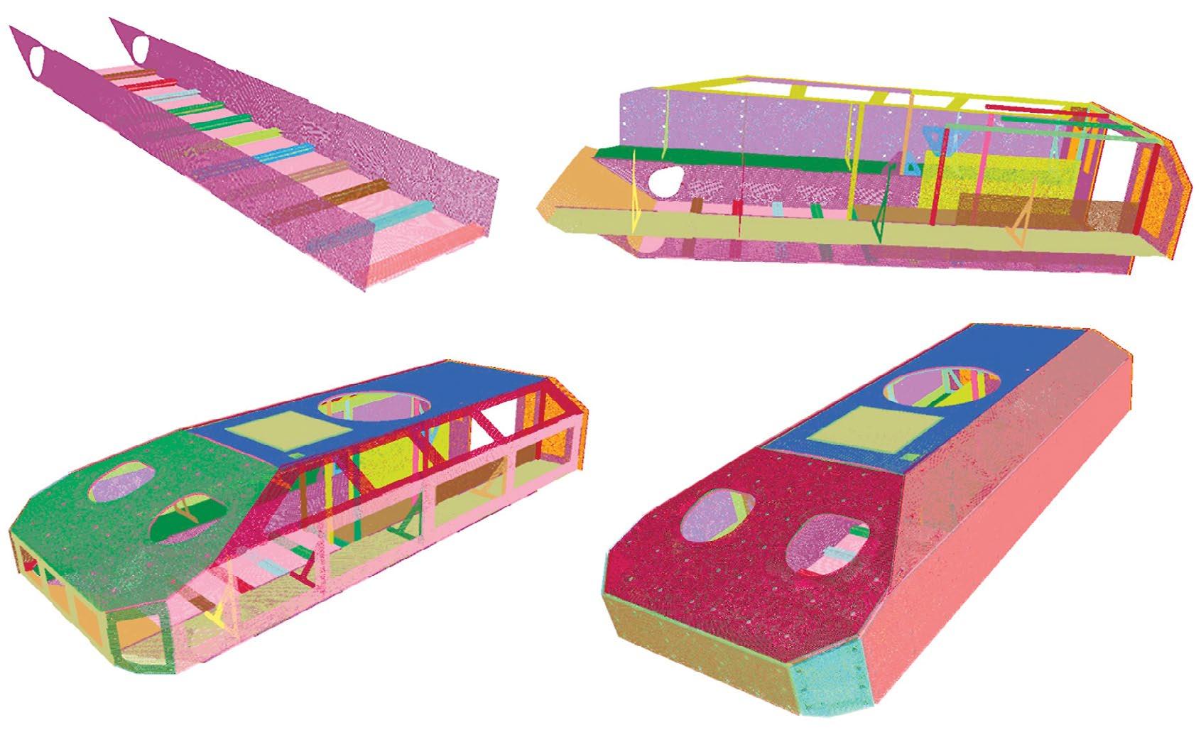
The multi-fidelity modeling approach uses tier levels to allow rapid design assessment.
These illustrations show the difference between a fast-running physics-based Tier 2 terminal ballistics model (left) and a highly detailed Tier 3 ballistic computation of a projectile striking an armor plate (right).
CAD format — referred to as STEP (Standard for The Exchange of Product model data) files — so any CAD system would be able to use the SwRI-developed ballistics and blast tools.
Multi-fidelity analysis
A major innovation that SwRI brought to the DARPA program was a multi-fidelity modeling approach employing different tier levels. Each tier had a different level of accuracy and uncertainty, in exchange for different amounts of computational time. For example, lower tier models are simpler, typically based on more assumptions about the physics. Because they include physics assumptions that then require less detailed computations, they have shorter computation run times, and thus are less expensive, but they also are less accurate and have a higher degree of uncertainty. The multi-tier approach allowed rapid exploration of the design space using fast-running lower tier models that sped up the conceptual design phase. In addition, by developing the different tiers of models, simpler, lower-tier models were quickly completed and thus working survivability models were always available in the software development process. This was beneficial for the concurrent development of other pieces of software and the definition of interfaces. Further, the various tiers of survivability solvers could also be used at a conceptual level, where only an outer “concept hull” needs to be defined. This allows a rapid initial design space exploration to determine the amount of armor and structure needed to survive a specified threat. As a design proceeds through more detail, the survivability analysis can be applied many times to allow the designer to make adjustments, such as at manufacturing seams, to ensure designer-level protections. By performing survivability analysis at the conceptual level, it is feasible to automate the design-space exploration.

One of the more tedious and time-consuming steps in survivability analysis is transforming CAD geometry to a format that is amenable to analysis tools. To make the tools more useful and to head toward the goal of “press one button in CAD to get your analysis,” the team developed tools to automatically mesh and then connect parts for the blast analysis. Our tools provided automatic meshing of various structural parts with a focus on producing quad-shell meshes, the types of meshes that have been shown to give the most accurate results in structural blast computations. (Structural parts include plates, panels, skins, and cross-section beams such as I-beams, C sections, and brackets.) The various parts are then automatically positioned in 3-D space, or “assembled” to produce the concept vehicle. Many different types of parts, with various meshing schemes, can be assembled this way. The emphasis is on robustness in automatically producing a good mesh for blast loading.
An important part of the assembly of a mesh is its connections. The team developed an electronic “bolter/welder tool,” which includes the ability to operate the tool both when connections are specified or in an automatic mode. The combination of the powerful automatic welding feature and the automatic generation of meshes greatly reduces analysis time. Welds are automatically inserted when free edges are seen to be near other objects. Bolts are automatically inserted when holes are found aligned and a bolt for the region has been specified. In particular, the tool can bolt multiple plates together (three or more) if the bolt holes line up.
Using the automated meshing feature, a designer can produce a vehicle, including interior structural members, in about four to five minutes using a conventional computer.
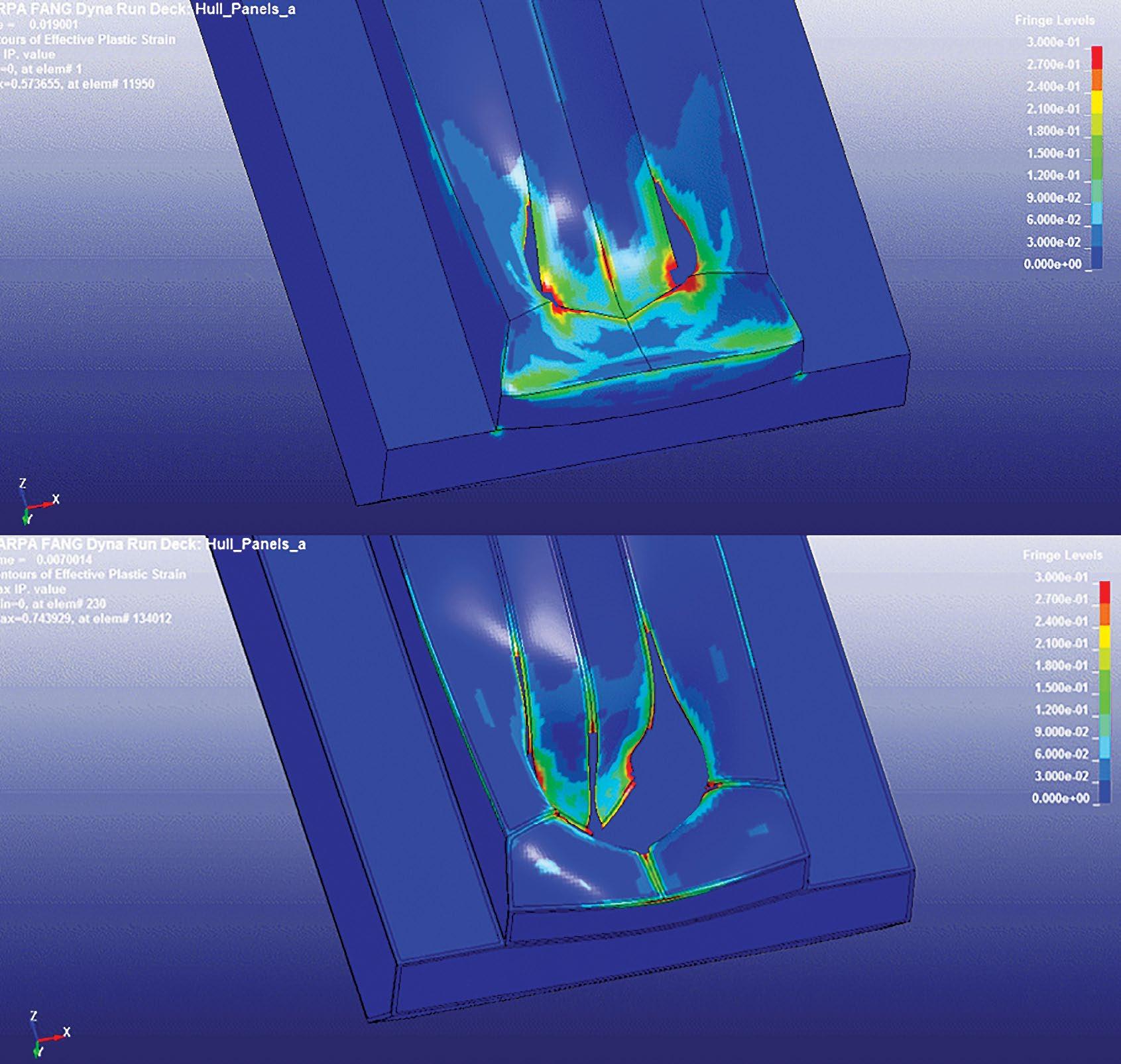
These images show a blast computation on a conceptual hull without (top) and with (below) a heat-affected zone (HAZ). Including the HAZ shows how the materials will be affected by a blast.
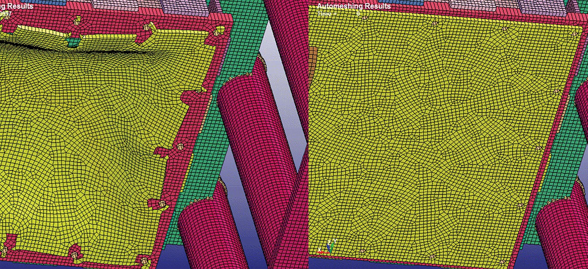
This computation shows that strong bolts can tear a test panel during loading (left), while weak bolts will break (right).
Another important element of the weld-connection and mesh-production capability is the inclusion of a heataffected zone (HAZ). Not including a HAZ leads to unrealistic strength predictions near joints. The automeshing tool, after connections are complete, passes through the mesh and produces a HAZ near all the welds. The material strength and damage properties are adjusted in the HAZ. It is important to include the HAZ in a mesh when performing blast computations, and the SwRI-developed tools did it automatically. During the connections step, a corrosion analysis also is performed.
Uncertainty quantification
Given the complexity of the computations and the multi-fidelity nature of the tools, the SwRI team quantified uncertainties and developed bounding models. The team developed ballistic and blast models to return 95-percent bounding results in addition to the nominal results. This means that, based on historical knowledge of variations in inputs into the models, one can find the performance bounds of the armors and blast mitigation systems. Using these statistical variations, many executions of the models were run a priori for certain situations to allow development of inputs to the physics-based models that would return the 95-percent bounding result. These computations used fast, off-line computations to develop an understanding of the influence of material, geometry, and other variability on the survivability results. With this, one can compute not only the nominal performance of the vehicle under a ballistic or blast threat event, but also the 95-percent bounding or worse-case response. This allows designers to know how close they are to meeting performance objectives, and
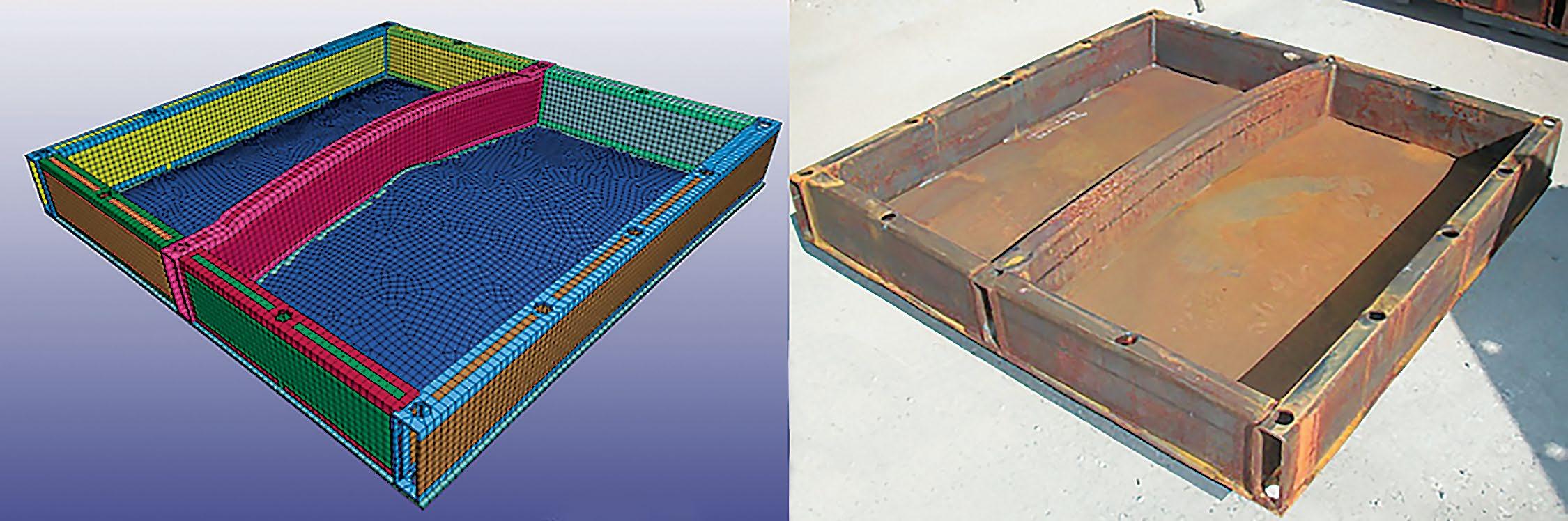
SwRI validated the blast survivability tools experimentally, such as this test designed to measure the loads on an armor plate produced by a buried charge.
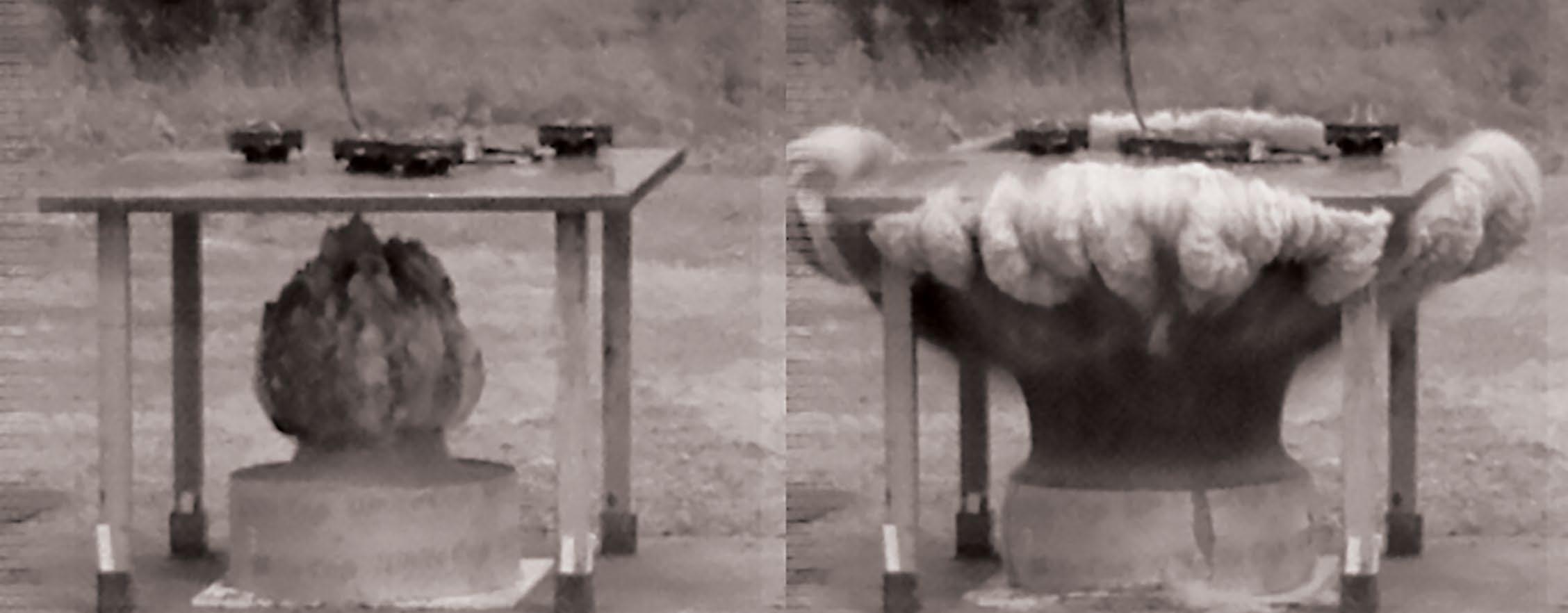
This side-by-side comparison shows a structural test specimen undergoing blast loads using the computational pipeline (left) and from an experiment conducted at the SwRI test range.
how much resilience is built into their design. This information can be used in an optimization study where robustness is one of the optimization parameters.
A sophisticated material model library
Survivability systems are used once, and the materials are used all the way through failure. Hence, it is necessary to know the large deformation and failure properties of the materials. As part of this program, the SwRI team compiled a database of survivability materials with constitutive properties that described the largedeformation, plastic-deformation, and flow as well as the damage properties. Large deformation means that solid materials reach a limiting strength. Sometimes the deformation is so significant that it causes the material to “flow” similarly to a viscous fluid. A permanent final deformation is referred to as plastic deformation.
Also, because blast loads for buried charges are still a research topic, the SwRI team performed experiments to further characterize the blast loads on simple structures. In addition, experiments were performed using v-shaped hull body designs because in some instances involving buried charges, v-shaped hulls have been shown to reduce loads imparted to the vehicle by underbelly blast.
The team also tested structural members to validate loads and the computational pipeline. Structural members were held in a test frame and blast loaded with buried charges. These same structures were blast-loaded using the computational pipeline. Through this work, as well as extensive use of historical data, the blast survivability tools were validated and showed good results.
Connecting the whole pipeline
Historically, manually performing all the steps in survivability analysis was quite tedious and time-consuming. A concerted effort to automate the whole process paid off by greatly reducing the amount of time required. During one of the DARPA exercises, teams said the survivability software allowed them to perform detailed conceptual design iterations in 30 minutes per iteration, something that previously may have taken two weeks per iteration. Other design teams praised the tools for their ease of use, speed, and the unique ability to convey survivability results to the vehicle designer. Extensive verification and validation exercises were performed on all the models to confirm their implementation and the implementation of the pipelines.
Future applications
The survivability analysis modeling tools are an important and successful part of the DARPA AVM effort. They perform as designed, fully automating complex steps that typically take manweeks to perform, and also providing estimates and bounds on the soundness of the answers. The SwRI team successfully demonstrated that automating steps ranging from material properties to meshing, connecting, and uncertainty quantification (UQ) analysis is a useful capability for designing blastand impact-resistant vehicles. In addition to their use by others, SwRI researchers have used these software tools in important follow-on design activities to analyze vehicle survivability.
Questions about this article? Contact Walker at (210) 522-2051 or james.walker@swri.org.
Acknowledgments
The authors acknowledge the contributions of SwRI staff members Dr. Charles E. Anderson Jr., Dan Pomerening, Dr. Elizabeth Trillo, Thomas Moore, Donald Grosch, David Riha, Alan Steiner, Scott Mullin, Dr. Alexander Carpenter, Joe Bradley, Andrew Barnes, Carl Weiss, P.A. Cox, John McFarland, Jeremy Zoss, Warren Couvillion, Katie McLoud, James Mathis, Ray Burgamy, Juan Magallan, Joe Elizondo, Danny Mendoza, Andrew Kammer, Dr. Kathryn Dannemann, and Joe Melig. SwRI acknowledges DARPA funding through contract number D12PC00466. The views, opinions, and/or findings contained in this article are those of the authors and should not be interpreted as representing the official views or policies of the Department of Defense or the U.S. Government. Approved for Public Release, Distribution Unlimited.
Virtual Inspection for Pipeline Corrosion An SwRI-designed computer model predicts corrosion risks for hard-to-inspect segments of pipeline
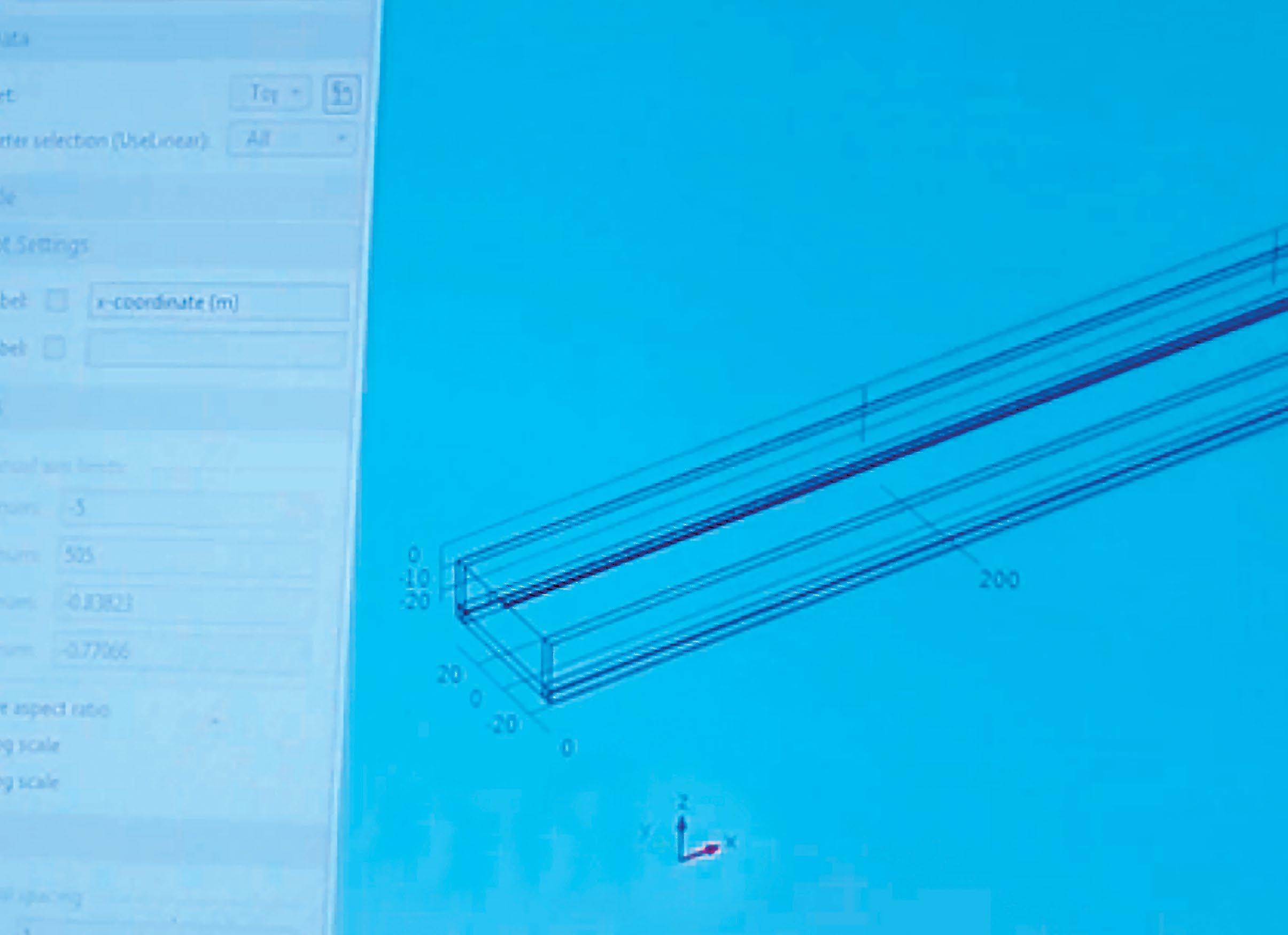
CAPCOM can be constructed for a specific set of geometric parameters and field conditions. The constructed model can then be visualized using the graphical user interface, as seen here.

By Pavan K. Shukla, Ph.D.
The oil and gas pipelines crisscrossing the nation pass beneath critical infrastructure, such as highways, railroads, and waterways, as well as population centers. Because more than half of U.S. pipelines date to the 1950s and 1960s, corrosion prevention and related repairs are increasingly important to avoid pipeline failures that can lead to toxic spills or devastating explosions.
Ironically, pipeline segments that lie beneath some of the most sensitive areas are also among the most difficult to inspect. Because these segments need extra protection to avoid damage from nearby excavation, settlement, traffic loads, and erosion, the carrier pipe is often encased within a larger-diameter reinforcing pipe. These segments, called cased pipelines, are subject to not only the normal corrosion caused by time, moisture, and soil chemistry, but also electrolytic corrosion caused by contact between the metals of the carrier pipe and its casing. In addition, the outer casings can adversely affect cathodic protection systems installed to reduce corrosion.
Cased pipelines often are sealed or have a separating medium such as wax placed between the layers of pipe. Over time, the seal can break, allowing the space between pipe layers to become filled with soil or water. Furthermore, the spacers that separate the carrier and casing pipe can break down over time, creating metallic contact between the carrier and casing pipes. It is estimated that there are close to 1 million cased crossings in the U.S., and approximately 40 percent of them may have degraded to the point of metallic contact between pipe layers.
External, visual inspection of cased pipelines is often impractical because of their location. Some are inaccessible, and in other cases obtaining a permit to perform an inspection dig may be difficult or impractical. Inspection of a cased pipe segment requires uncovering the segment, opening the space between pipe layers, and inserting an instrumented
Dr. Pavan Shukla is a senior research engineer in the Geosciences and Engineering Division. He has expertise in modeling corrosion and chemical processes using finite and boundary element methods. His current work includes assessing degradation on both metallic and nonmetallic pipeline materials, and predicting localized-corrosion-induced damage.
probe between layers to inspect the inner pipe’s integrity.
Internal inspection by sending a tubular, instrumented device known as a “pig” through the carrier pipeline along with the product requires no excavation, but it is expensive and usually done only once every five years.
Modeling hidden risks
Engineers at Southwest Research Institute (SwRI) have developed the CAsed Pipeline COrrosion Model, or CAPCOM®, to predict the corrosion condition of these double-layer pipeline
Pipeline failures can lead to devastating explosions, such as this one in San Bruno, Calif., in 2010.

segments. CAPCOM uses a unique, specialized application of the finite element method (FEM) to arrive at a mathematical model of the pipeline’s condition in relation to corrosion. Mathematicians use FEM to model complex surfaces, structures, or even weather systems, by breaking the problem down into a large number of much smaller, simpler-to-solve components called finite elements. (Imagine approximating the area of a circle by turning it into a great number of extremely thin, pie-slice triangles.) Solutions to those smaller element equations are then re-combined into a solution that approximates the whole. For a cased pipeline, FEM provides a tool for making improved predictions of the integrity, service life, and corrosion risk.
A common source of corrosion in pipelines and many other metallic structures, such as ships or offshore oil platforms, is an electron exchange that happens when two dissimilar metals touch each other or are linked by an electrically conductive fluid, or electrolyte. (Salty sea water is an electrolyte; so are wet soil and rainwater with dissolved minerals.) As with a battery when the switch is turned on, a flow of electrons (electric current) begins, robbing metal molecules from the negative connection, or anode, and depositing them at the positively charged end, or cathode.
To mitigate this metal loss, pipeline operators employ cathodic protection (CP), which makes the metal pipe the cathode of the “battery” and substitutes an easily corroded ”sacrificial” metal to act as the anode. The sacrificial metal corrodes instead of the protected metal of the pipeline. For pipelines and some other large structures, a direct-current electrical power source is installed to provide sufficient current. CP systems are used to control corrosion on critical steel structures of all sizes, from pipelines and ships to outboard motors and home water heaters.
In pipeline segments where visual or inline inspection is limited, CAPCOM can provide valuable information on corrosion conditions. By estimating pipe-tosoil electrical potential along the cased pipeline segment, and possible corrosion rates on the carrier pipe, CAPCOM can help determine whether the cased pipeline section is adequately protected, or if it is time for preventive maintenance.
CAPCOM can model complex corrosion scenarios, including electrolytic or electrolytic-plus-metallic contact between the carrier and the casing pipe, defects in the carrier pipe’s coating, or combinations of these. It also can identify the level of polarization of the casedpipeline segment and the rest of the nearby pipeline when there is electrolytic contact between the carrier and casing.
For pipeline segments that use a CP system to prevent electrolytic corrosion, CAPCOM can quantify the system’s effectiveness for mitigating corrosion. It also can quantify how much more CP current may be needed to adequately protect the pipeline when electrolytic contact between the casing and carrier pipe has been confirmed.
How it works
CAPCOM employs the same basic mathematical input parameters used in existing models of CP systems for uncased pipelines (such as coating quality, pipeline material, anode output,
A cased pipeline with the carrier pipe inside a larger diameter casing pipe, as shown here, presents special problems with corrosion inspection.

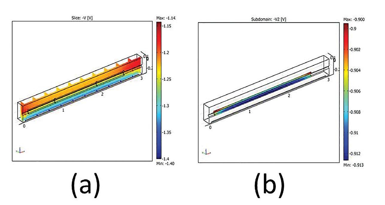
When comparing the CAPCOM model (see above) with an inspection, electric potentials predicted by the model (represented by solid lines in the figure at the right) closely match the potentials measured by actual inspection (represented by symbols).

and the electrical current flowing through the soil and the electrolyte). However, it adds inputs related to the casing pipe itself. For example, CAPCOM inputs for both cased and uncased sections of the pipeline include their dimensions and coating properties, plus soil properties and any electrolytic properties that may exist inside the space between the casing and carrier pipe. CAPCOM analysis also includes the CP design used to protect both cased and carrier pipes in its models.
CAPCOM’s FEM method solves the model equations for predicting corrosion conditions of the cased-pipeline section. Using the FEM formulation, CAPCOM also can represent varying conditions that affect the carrier pipe, such as how the soil conducts or resists electrical conduction at different locations near the cased portion of the pipeline.
This capability sets CAPCOM apart from other CP models, which use a different modeling approach known as the boundary element method (BEM). BEM-based software works best when modeling a homogenous medium (such as soil of uniform properties surrounding a pipeline) but it has limited ability to model how the surrounding soil or other fill material with varying chemical composition and moisture content affects pipeline corrosion. This limitation precludes using BEM tools for complex cased crossing conditions.
CAPCOM explicitly accounts for electrolytic-plus-metallic contact between carrier and casing pipe and the soil outside the cased crossing to determine the corrosion condition of the carrier pipe. In CAPCOM, metallic contact and electrolytic contact are accounted for by modeling a resistor and an electrolyte, respectively, between the carrier and casing pipes. CAPCOM also includes specifications for modeling “coating holidays” — places where the protective coating is damaged or missing — both inside and outside the cased pipeline section. After all of the
parameters are entered and limits are defined, CAPCOM models the corrosion environment and presents its results in two- and three-dimensional plots. These plots include pipe-to-electrolyte potential for the cased and uncased carrier pipeline sections, as well as the state of the electrical current the CP system supplies to the carrier pipe. The model reveals whether the CP current is diverted to the casing pipe, indicating metallic contact between carrier and casing pipes. With CAPCOM, users can determine the level of CP the carrier pipe will need and evaluate the risk of external corrosion at “holidays” on the carrier pipe inside the casing.
Comparing costs
CAPCOM saves costs compared to both visual and in-line inspections. Visual inspection requires removing the topsoil over the pipeline, exposing the two ends of the casing pipe, and probing the interior with an inspection tool. Visual inspection can cost $50,000 to $100,000, depending on the size and location of the casing. By comparison, analyzing pipelines with CAPCOM software requires only the associated engineering time for the analysis, once the software is purchased. Although the software has an estimated cost of $35,000, it can be used numerous times, allowing this cost to be spread over a number of evaluations.
In-line inspection using an instrumented pig costs $10,000 to $20,000 per mile, but it generally must cover long segments of pipeline to be practical, because the above-ground “launch” and “trap” stations for inserting and recovering the pig are usually about 20 to 50 miles apart. Also, pig inspections are carried out as often as every five years, which could, in many situations, be insufficient to detect and prevent corrosion-induced damage of carrier pipe.
Limitations
CAPCOM does require a large number of input parameters to simulate the corrosion conditions of a cased pipeline. These parameters are determined by field measurements, which may not always be available. However, the SwRI team addressed this potential limitation by formulating CAPCOM such that when a parameter value is unavailable, a nominal value with a variability range can be substituted. Thus, pipeline behavior can be simulated for a range of parameters, yielding a range of expected corrosion conditions and electrode potential of the pipeline casing.
Current and future applications
As a modeling tool, CAPCOM has applications not only as an alternative to direct pipeline inspection but also as a tool to assess corrosion-inhibiting products used on pipelines. CAPCOM potentially can save human lives and millions of dollars’ worth of private property and public infrastructure. It enables reliable inspection and life prediction of critical pipeline segments that are, by their very nature, difficult to inspect.
Questions about this article? Contact Shukla at (210) 522-6534 or pavan.shukla@swri.org.
For more information, see “Development of Cased-Pipeline Corrosion Model and Its Validation with Experimental Data,” by P.K. Shukla, A.Nordquist, and F. Song. Published in the Proceedings of CORROSION 2014, paper No. 4353, Corrosion 2014, San Antonio, March 2014.
ABSTRACT
A large-scale FEM-based model was developed for cased pipelines. The model contained features that could be used to evaluate the condition of a pipeline inside casing, without the difficulty and expense of measuring cathodic polarization within the casing. Casings are used to provide load-bearing protection to carrier pipelines at crossing locations, such as highways and railroad lines. The Pipeline Research Council International has published a report containing multiple experiments on cased pipeline. In these experiments, eight parameters were varied; four of them were at 2 levels and four were 3 levels. Overall, the report contained 18 repeats of 36 unique experiments. A computational model of the cased pipeline was developed to simulate experimental conditions in the report using a finite element method-based computer code. This model included significant features of the experimental apparatus. Comparisons were made between the model and the experimental measurements. The model details and its comparison with the experimental data are presented.
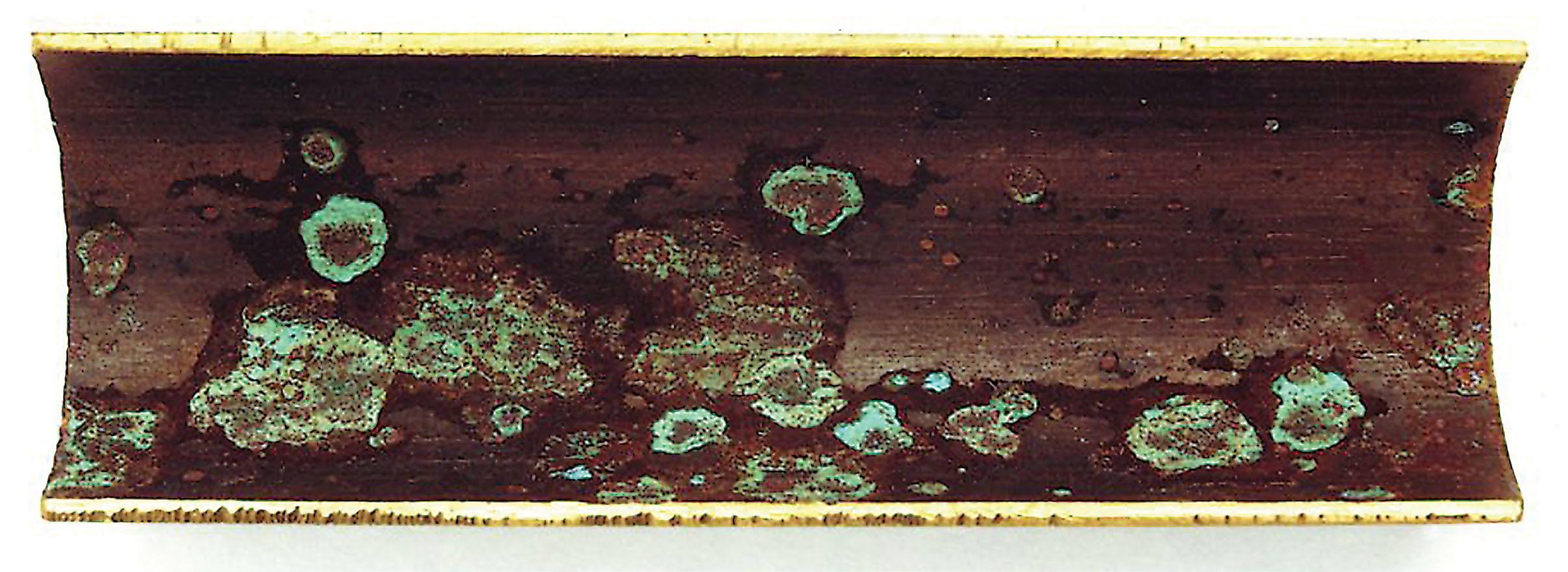
Green areas are corrosion on the inside surface of a carrier pipe.