ANSI/APSP/ICC-16 2017
American National Standard for
Suction Outlet Fitting
Assemblies (SOFA) for Use in Pools, Spas and Hot Tubs
Approved August 18, 2017


ANSI/APSP/ICC-16 2017
American National Standard for
Assemblies (SOFA) for Use in Pools, Spas and Hot Tubs
Approved August 18, 2017
ANSI/APSP/ICC-16 2017
SECRETARIAT:
American National Standard for Suction Outlet Fitting Assemblies (SOFA) for Use in Pools, Spas, and Hot Tubs
Association of Pool & Spa Professionals 2111 Eisenhower Avenue Alexandria, VA 22314 (703) 838-0083 APSP.org
Approved August 18, 2017
American National Standards Institute (ANSI)
This standard is published in partnership with the International Code Council (ICC). ICC develops and publishes the International Building Code® (IBC®) and International Residential Code® (IRC®), which are adopted as the basis for the building codes used in most states and jurisdictions within the United States. Additionally, APSP and ICC have collaborated to develop the first comprehensive model swimming pool and spa code, known as the International Swimming Pool and Spa Code® (ISPSC®). This landmark document incorporates and references material from ANSI/APSP standards and ICC’s model codes, to create a stand-alone code that is consistent with codes and standards from both organizations. These codes and standards are the result of a joint effort between ICC and APSP as a service to both the swimming pool and spa community and building code professionals. It is the hope of both organizations that they will lead to enhanced safety for pool and spa users around the world.
Approval of an American National Standard requires verification by the American National Standards Institute (ANSI) that the requirements for due process, consensus, and other criteria for approval have been met by the standard developer. Consensus is established when, in the judgment of the ANSI Board of Standards Review, substantial agreement has been reached by directly and materially affected interests. Substantial agreement means much more than a simple majority, but not necessarily unanimity.
Consensus requires that all views and objections be considered and that a concerted effort be made toward their resolution. The use of American National Standards is completely voluntary; their existence does not in any respect preclude anyone, whether he has approved this standard or not, from manufacturing, marketing, purchasing, or using products, processes, or procedures not conforming to the standards.
The American National Standards Institute does not develop standards and will in no circumstances give an interpretation of any American National Standard (ANS). Moreover, no person shall have the right or authority to issue an interpretation of an American National Standard in the name of the American National Standards Institute. Requests for interpretations should be addressed to the secretariat or sponsor whose name appears on the title page of this standard.
NOTICE: This American National Standard may be revised or withdrawn at any time. The procedures of the American National Standards Institute require that action be taken periodically to reaffirm, revise, or withdraw this standard.
This voluntary standard has been developed under the published procedures of the American National Standards Institute (ANSI). The ANSI process brings together volunteers representing varied viewpoints and interests to achieve consensus.
APSP does not write the standards. Rather, APSP facilitates a forum for its members, and others interested in pool and spa design and safety, to develop standards through the consensus procedures of the American National Standards Institute (ANSI). While the APSP administers the process and establishes rules to promote fairness in the development of consensus, it does not independently test, evaluate, or verify the accuracy of any information or the soundness of any judgments contained in its codes and standards.
In issuing and making this document available, the APSP is not undertaking to render professional or other services for or on behalf of any person or entity. Nor is the APSP undertaking to perform any duty owed by any person or entity to someone else. The APSP disclaims liability for any personal injury, property, or other damages of any nature whatsoever, whether special, indirect, consequential, or compensatory, directly or indirectly resulting from the publication of, use of, or reliance on this document.
The APSP has no power, nor does it undertake, to police or enforce compliance with the contents of this document. The APSP does not list, certify, test, or inspect products, designs, or installations for compliance with this document.
Any certification or other statement of compliance with the requirements of this document shall not be attributable to the APSP. Any certification of products stating compliance with requirements of this document is the sole responsibility of the certifier or maker of the statement. The APSP, its members, and those participating in its activities do not accept any liability resulting from compliance or noncompliance with the provisions given herein, for any restrictions imposed on materials, or for the accuracy and completeness of the text.
Anyone using this document should rely on his or her own independent judgment or, as appropriate, seek the advice of a competent professional in determining the exercise of reasonable care in any given circumstance. It is assumed and intended that pool users will exercise appropriate personal judgment and responsibility and that public pool owners and operators will create and enforce rules of behavior and warnings appropriate for their facility.
Copyright Notice
Copyright ©2017 by The Association of Pool & Spa Professionals, 2111 Eisenhower Avenue, Alexandria, VA 22314-4695. Printed in the United States of America. All rights reserved. No part of this book may be reproduced, stored in a retrieval system, transcribed or transmitted, in any form or by any means or method, electronic, mechanical, photocopy, recording, or otherwise, without advance written permission from the publisher: The Association of Pool & Spa Professionals, 2111 Eisenhower Avenue, Alexandria, VA 22314-4695.
“APSP,” “The Association of Pool & Spa Professionals,” and the APSP logo are trademarks of The Association of Pool & Spa Professionals.
Cover Photo: Courtesy of Pool Environments, Inc. (Plano, Texas) 2017 APSP Awards of Excellence (AOE) Bronze Winner
This Foreword is not part of the American National Standard ANSI/APSP/ICC-16 2017. It is included for information only.
The ANSI/APSP/ICC-16 2017, Standard for Suction Outlet Fitting Assemblies (SOFA) for Use in Pools, Spas, and Hot Tubs, was approved by the American National Standards Institute (ANSI) on August 18, 2017. This standard is a revision of ANSI/ APSP-16 2011 Standard for Suction Fittings for Use in Swimming Pools, Wading Pools, Spas, and Hot Tubs.
The objective of this standard is to provide minimum guidelines for testing, product-marking requirements, installation and maintenance instructions. Under the Virginia Graeme Baker Pool and Spa Safety Act (VGBA) drain covers manufactured on or after November 24, 2020, are required to comply with this standard.
ANSI/APSP/ICC-16 2017 contains additional sections beyond the requirements for the drain cover or SOFA itself. These provisions are outside the scope of the U.S. Consumer Product Safety Commission’s (CPSC's) authority under section 1404(b) of the VGBA. These sections, which are detailed in Non-Mandatory Appendix F, Tables 1 through 4, are classified as voluntary, unless adopted into state or local codes, in which case they will become mandatory in those jurisdictions.
The non-mandatory Appendices included with this Standard are provided by the APSP-16 Standard Writing Committee (SWC) to assist the user by highlighting key compliance elements, their location in the Standard along with additional detail. The Appendices are not a substitute for the text of the Standard and all entities subject to this Standard are required to follow the mandatory provisions, as well as applicable Federal Law and applicable state and local requirements.
Non-Mandatory Appendix E is intended to enhance consistency between accredited testing laboratories, and therefore extends beyond the International Organization for Standardization (ISO) 17025 test laboratory accreditation, which is limited to technical requirements that demonstrate competence in performing testing and using equipment within the scope of this Standard. Elements of the ISO 17025 Standard that extend beyond the Scope of this Standard, including those pertaining to the organization of testing facilities, the manner in which they contract with clients, purchase supplies or provide overall services are not mandatory under this Standard.
The APSP does not certify, test or endorse any product.
The recommendations and testing practices in this standard are based upon sound engineering principles, research, and field experience that, when applied properly, contribute to the delivery, installation and maintenance of a safe product.
The words “safe” and “safety” are not absolutes. While the goals of this standard are to design, construct and maintain a safe, enjoyable product, it is recognized that risk factors cannot, as a practical matter, be reduced to zero in any human activity. This standard does not replace the need for good judgment and personal responsibility. In permitting use of the pool or spa by others, owners must consider the skill, attitude, training, and experience of the expected user.
As with any product, the specific recommendations provided by the manufacturer should be carefully reviewed and followed, with regard for installation, use, and maintenance. This includes replacement before expiration of the service “Life in Years”, by which date the product is no longer suitable for use and must be replaced.
This standard was prepared by the APSP-16 Suction Outlet Fitting Assemblies (SOFA) for Use in Pools, Spas, and Hot Tubs (Drain Cover) Standard Writing Committee of the Association of Pool and Spa Professionals (APSP) in accordance with ANSI Essential Requirements: Due process requirements for American National Standards (ANS)
Consensus approval was achieved by a ballot of the balanced APSP Standards Consensus Committee (SCC) below and through an ANSI Public Review process. The ANSI Public Review provided an opportunity for additional input from industry, academia, regulatory agencies, safety experts, state code and health officials, and the public at large.
Suggestions for improvement of this standard should be sent to the Association of Pool and Spa Professionals, 2111 Eisenhower Avenue, Alexandria, VA 22314.
Consensus approval in accordance with ANSI procedures was achieved by ballot of the following APSP Standards Consensus Committee (SCC). Inclusion in this list does not necessarily imply that the organization concurred with the submittal of the proposed standard to ANSI.
All American Custom Pools & Spas, Inc.
Carefree Pools, Inc.
Idaho Pool Remodeling. ..........................
Hayward Industries, Inc.
Horner Xpress South Florida
Latham Pool Products ............................
Master Spas Inc.
Paragon Pools
S.R. Smith, LLC .................................
Van Kirk & Sons, Inc.
American Red Cross ............................
Chesapeake Aquatic Consultants, LLC
Conroe Independent School District, TX
John C. Romano, CSP, CBP
John Bently, CSP, CBP
Scott Heusser, CPO, CPOL, CPI, CAEA
John O’Hare, CSP, CBP
Bill Kent, Ph.D.
Michael Tinkler
Nathan Coelho
Joe Vassallo, CBP
Bill Svendsen
Don Cesarone, Jr.
Connie Harvey
Frank Goldstein, CSP, CBP
Louis Sam Fruia, M.Ed., AFO, CPO/CPI Consultant
Gro Development (YMCA of the USA)
Higgins Environmental Solutions (National Environmental Health Association)
John Leas
Albert Tursi
Florence Higgins, R.S. MasterCorp, Inc.
(American Hotel & Lodging Association - AHLA) .........
Walt Disney’s Water Parks and and Miniature Golf (The Walt Disney Company)
World Waterpark Association
Water Technology Inc.
User
City of Goodyear, AZ .............................
City of Martinsville, VA
City of Winter Springs, FL
CSG Consultants
Illinois Department of Health
International Code Council (ICC) ....................
N.J. Dept. of Community Affairs, Codes
Texas Department of State and Health Services .........
Town of Flower Mound, TX
Washington State Department of Health
U.S. Consumer Product Safety Commission
Tony Mendez
Michael Beatty
Rick Root
Chuck Neuman
Ed Kulik
Kris Bridges, MCP, CBO, CZA, SCC Chair
Joseph R. Crum, CBO
Mike Teemant
Justin DeWitt, P.E., LEED AP
Lee Clifton
Thomas Pitcherello, SCC Vice Chair
Katie O. Moore, R.S., CPO
Thomas Vyles, REHS/RS
Paul Reeves
Perry Sharpless * *non-voting
In accordance with American National Standards Institute (ANSI) procedures, this document will be reviewed periodically. The Association of Pool & Spa Professionals welcomes your comments and suggestions, and continues to review all APSP standards, which include:
ANSI/APSP/ICC-1 Standard for Public Swimming Pools
ANSI/NSPI-2 Standard for Public Spas
ANSI/APSP/ICC-3 Standard for Permanently Installed Residential Spas and Swim Spas
ANSI/APSP/ICC-4 Standard for Aboveground/Onground Residential Swimming Pools
ANSI/APSP/ICC-5 Standard for Residential Inground Swimming Pools
ANSI/APSP/ICC-6 Standard for Residential Portable Spas and Swim Spas
ANSI/APSP/ICC-7 Standard for Suction Entrapment Avoidance in Swimming Pools, Wading Pools, Spas, Hot Tubs, and Catch Basins
ANSI/APSP/ICC-8 Standard for Model Barrier Code for Residential Swimming Pools, Spas and Hot Tubs
ANSI/IAF-9 Standard for Aquatic Recreation Facilities
ANSI/APSP-11 Standard for Water Quality in Public Pools and Spas
ANSI/APSP/ICC/NPC-12 Standard for the Plastering of Swimming Pools and Spas
ANSI/APSP/ICC-13 Standard for Water Conservation Efficiency in Pools, Spas, Portable Spas and Swim Spas
ANSI/APSP/ICC-14 Standard for Portable Electric Spa Energy Efficiency
ANSI/APSP/ICC-15 Standard for Residential Swimming Pool and Spa Energy Efficiency
APSP 2013 Workmanship Guidelines and Practices
APSP-16 Standard Writing Committee
A & A Manufacturing
Don McChesney
Mike Marshall**
AquaStar Pool Products ............... Steve Barnes, APSP-16
Aquatic Development Group
Balboa Water Group
Hayward Industries, Inc
Hayward Pool Products
SWC Chair man
Jim Dunn
Graham Campbell
Bob Spillar**
John O'Hare
Alan Levin
International Association of Plumbing and Mechanical Officials (IAPMO) EGS ....... Tony Zhou
NSF International Kevin Schaefer
Paramount Pool & Spa Products
Dominic Conn
Pentair Water Quality Systems .......... John Vasarhelyi
Stingl Products
Texas Department of State Health Services
Afras Industries, Inc.
Code Compliance ..................
Reza Afshar, P.E., C.G.E.
Gary S. Duren
Color Match Pool Fittings (CMPF) Todd Krumbein
Custom Molded Products (CMP) Angelo Pugliese
International Code Council (ICC) ...... Maribel Campos
MasterSpas
Neptune Benson
PSD Industries LLC
POOLCORP
Kenneth Gregory**
David Stingl
Katie Moore, R.S., CPO
U. S. Consumer Product Safety Commission (CPSC) Perry Sharpless*
Underwriters Laboratories (UL) Gary Siggins
Walt Disney’s Water Parks and Miniature Golf (The Walt Disney Company)
Lee Clifton
Nathan Coelho
Steve Hawksley
New Water Solutions, Inc. ............ Ron Schroader
Paul McKain
Dominick J. Latino III, Esq.
Shasta Industries .................. Andy Blake
Speck Pumps
Vacless Systems Inc.
Gary Walt
Hassan Hamza
Watkins Engineering ................ Mike McCague
Vac-Alert .......................... Paul Pennington
Michael Beatty
Waterway Plastics Ray Mirzaei
APSP Legal Counsel
Lester Schwab Katz & Dwyer, LLP ........ Steve Getzoff,* Esq.
APSP Staff
Carvin DiGiovanni,* Vice President, Technical and Standards
Susan J. Hilaski,* Director, Standards Promotion & Adoption
* non-voting
** alternate voting member
This standard establishes materials, testing, use, installation, and marking requirements for new or replacement bather-accessible Suction Outlet Fitting Assemblies (SOFAs), other than maintenance drains, that are designed to be fully submerged for use in any pool, which include, but are not limited to a swimming pool, hot tub, spa, portable spa, or non-portable wading pool, or other aquatic venue intended for swimming or recreational bathing. The term pool is used throughout this standard as an identifier for these bodies of water.
1.1.1 Effective date. This standard becomes effective 18 months after adoption by the U.S. Consumer Product Safety Commission (CPSC).
1.1.2 Existing product compliance. SOFA components that were manufactured or installed before the effective date of this standard, and that meet APSP-16 2011, shall be considered in compliance with this standard.
1.1.3 Service life. Cover/grates and all other SOFA components shall be replaced at or before the end of their service life as stated by the manufacturer. Service life begins the month and year in which a SOFA component is installed with or without water.
1.1.4 Skimmers are excluded from the scope of this standard.
1.1.5 Vacuum cleaner ports. Vacuum connection covers are excluded from the scope of this standard. See the International Association of Plumbing and Mechanical Officials (IAPMO) SPS-4, Special Use suction fittings for Swimming Pools, Spas and Hot tubs for Suction-Side Automatic Swimming Pool Cleaners.
1.2.3 Self-contained spa SOFAs: A manufactured, restricted use, SOFA that is distributed exclusively as a component of a self-contained factory-manufactured spa, where the self-contained spa SOFA has been further evaluated while installed in the spa at the time it is tested and certified in conformance with ANSI/UL 1563.
1.2.4 Swim jet combination SOFAs: A manufactured SOFA that merges a suction port(s) and discharge port(s) into a single assembly for use in a single SOFA system and/or a multiple SOFA system
1.2.5 Registered Design Professional SOFAs: A fieldbuilt SOFA that is typically used for high flow rate systems found in large public pools and water park type recreation facilities. They shall be designed using only sumps that qualify as unblockable. The term RDP SOFA is used throughout this standard as an identifier for this type of SOFA.
1.2.6 Venturi SOFAs: A manufactured, restricted use, blockable SOFA distributed exclusively as a component of a water-driven suction system that returns all water from the Venturi SOFA to the pool without it passing through a pump.
1.3 Certifications
1.3.1 Prohibited certifications.
1.3.1.1 Manufactured SOFAs and RDP SOFAs that are not evaluated to all applicable sections or fail any applicable requirement of this standard shall not be certified as meeting this standard.
1.3.2 Required testing and certification.
1.2.1 General purpose SOFAs: A manufactured SOFA for transferring water from the pool directly or indirectly to a pump.
1.2.2 Maintenance drain and fire suppression water source outlet: A manufactured, restricted use fitting used only by pool maintenance personnel or fire suppression personnel ONLY at times when the pool is closed to bathers. Maintenance drains and fire suppression water source outlets are exempt from Sections 5 and 6 of this standard. Any SOFA certified to this standard shall be permitted to serve this purpose.
1.3.2.1 Manufactured SOFAs shall be tested by a laboratory in conformance with paragraph 1.3.4 and certified by an agency in conformance with paragraph 1.3.5.
1.3.2.2 RDP SOFAs shall be designed, installed, and certified in conformance with all applicable requirements of this standard by a registered design professional whose credentials are in conformance with the paragraph 1.3.6.
1.3.2.3 Manufacturers and registered design professionals of SOFAs intended to enter commerce within the United States shall make available a General Certificate of Conformity (GCC) for each SOFA model as required by 16 CFR Part 1450.
1.3.3 Prohibited installations.
1.3.3.1 Pools equipped with a SOFA(s) that does not result in an individual suction system flow rating equal to or greater than the pool’s actual individual suction system flow rate, or pools with a SOFA(s) that was not installed in accordance with the SOFA specific instructions, including fasteners used with preexisting components, shall not be considered in conformance with this standard.
1.3.3.2 Cover/grate shall only be installed on existing SOFA components if the replacement cover/ grate manufacturer has designated the products as suitable for attachment to previously installed SOFA components. When used, the designation shall include how to identify compliant fastener attachment points and/or how to install the replacement cover/grate without using existing attachment points.
1.3.4 Testing laboratory accreditation. Laboratories shall be accredited to ISO 17025 and shall ensure all testing of manufactured SOFAs conform to this APSP-16 standard.
1.3.5 Certification agency accreditation. Certification bodies shall be accredited to ISO 17065, and shall provide certification of all manufactured SOFAs to this APSP-16 standard.
1.3.6 Registered design professional accreditation.
Any individual who designs and certifies RDP SOFAs shall be registered or licensed to practice their design profession as defined by the statutory requirements of the professional registration laws of the state or jurisdiction in which the pool receiving the RDP SOFA is located.
1.3.7.2 For all SOFA configurations with a suction piping opening greater than 16 in. (406 mm) from the finished surface of the pool, measured in accordance with Section 1.3.7.1, the cover/grate shall be tested on one SOFA configuration in accordance with Section 5. The SOFA configuration tested shall be one using the largest pipe opening(s) size specified for the cover/grate resulting in the highest flow potential.
1.3.8 Flow rating determination – RDP SOFAs. The registered design professional shall determine the SOFA’s flow rating in accordance with Section 3.9.
1.3.7 Flow rating determination – manufactured SOFAs. The flow rating for each manufactured SOFA configuration shall be determined by the lowest passing flow rate obtained during any of the Type 1 hair tests, the Type 2 hair tests, and the body-blocking element (BBE) test, unless the SOFA manufacturer specifies a lower flow rate, which shall then be the maximum allowable flow rate for that SOFA.
1.3.7.1 For all SOFA configurations with a suction piping opening less than 16 in. (406 mm) from the finished surface of the pool, the cover/grate shall be tested on each SOFA configuration in accordance with Section 5. The distance shall be measured from the SOFA’s designated finished surface of the pool using a string line to represent the greatest distance Type 1 and Type 2 hair can travel into the cover/grate and sump. Each of these SOFA configurations shall receive a flow rating.
1.3.9 Water velocity limits. For purposes of suction safety, this standard provides SOFA configuration-specific water velocity limits through a cover/grate based on the SOFA tests of Sections 5 and 6. These limits are expressed in gallons per minute (gpm), which can be converted directly into feet per second (fps) velocity units when desired. State and Local Codes may limit flow through a cover/grate based on water velocity (fps) rather than the marked flow rate (gpm) of the cover/grate. When this methodology is used, the resultant flow rating shall not exceed the cover/grate’s SOFA-specific flow rating in gallons per minute.
1.3.10 Removal force calculation. Table 1, Applicable Body Block Element – Calculation of Removal Force, referenced in ANSI/APSP – 16 2011 has been replaced with Equation 2 in Section 6.4.
1.3.11 Units. When values are stated in U.S. Customary units and in the International System of Units (SI), the values stated in U.S. Customary units shall be considered as the standard.
1.4
Because the scope of this standard is directly related to suction fittings, it is important to mention that the fittings themselves represent only one portion of the suction entrapment scenario. Additional standards to be consulted to provide coverage for the various other potential hazards in swimming pools, wading pools, spas, and hot tubs and aquatic recreation facilities. These other standards include, but are not limited to, the following:
16 CFR Part 1450 Virginia Graeme Baker Pool and Spa Safety Act
ANSI/APSP/ICC-1 Standard for Public Swimming Pools
ANSI/NSPI-2 Standard for Public Spas
ANSI/APSP/ICC-3 Standard for Permanently Installed Residential Spas and Swim Spas
ANSI/APSP/ICC-4 Standard for Above-ground/On-Ground Residential Swimming Pools
ANSI/APSP/ICC-5 Standard for Residential In-Ground Swimming Pools
ANSI/APSP/ICC-6 Standard for Residential Portable Spas and Swim Spas
ANSI/APSP/ICC-7 Standard for Suction Entrapment
Avoidance In Swimming Pools, Wading Pools, Spas, Hot Tubs, and Catch Basins
ANSI/APSP/ICC-8 Standard for Model Barrier Code for Residential Swimming Pools, Spas, and Hot Tubs
ANSI/IAF-9 Standard for Aquatic Recreation Facilities
ANSI/APSP/ICC-14 Standard for Portable Electric Spa Energy Efficiency
ANSI/APSP/ICC-15 Standard for Residential Swimming Pool and Spa Energy Efficiency
ASME A112.19.17 Manufactured Safety Vacuum Release Systems (SVRS) for Residential and Commercial Swimming Pool, Spa, Hot Tub, and Wading Pool Suction Systems
ASTM F2387 Standard Specification for Manufactured Safety Vacuum Release Systems (SVRS) for Swimming Pools, Spas and Hot Tubs
UL 1563 Standard for Electric Spas, Equipment Assemblies, and Associated Equipment
1.5 Normative References
The following documents are referenced in this standard. Unless otherwise specified, the latest edition in effect shall apply:
ANSI/APSP/ICC-8 Standard for Model Barrier Code for Residential Swimming Pools, Spas, and Hot Tubs
ANSI/IAF-9 Standard for Aquatic Recreation Facilities
ANSI/APSP/ICC-14 Standard for Portable Electric Spa Energy Efficiency
ANSI/APSP/ICC-15 Standard for Residential Swimming Pool and Spa Energy Efficiency
ASME A112.19.17 Manufactured Safety Vacuum Release Systems (SVRS) for Residential and Commercial Swimming Pool, Spa, Hot Tub, and Wading Pool Suction Systems
ANSI/APSP/ICC-1 Standard for Public Swimming Pools
ANSI/NSPI-2 Standard for Public Spas
ANSI/APSP/ICC-3 Standard for Permanently Installed Residential Spas and Swim Spas
ANSI/APSP/ICC-4 Standard for Above-ground/On-Ground Residential Swimming Pools
ANSI/APSP/ICC-5 Standard for Residential In-Ground Swimming Pools
ANSI/APSP/ICC-6 Standard for Residential Portable Spas and Swim Spas
ANSI/APSP/ICC-7 Standard for Suction Entrapment Avoidance In Swimming Pools, Wading Pools, Spas, Hot Tubs, and Catch Basins
ASME B1.20.1 Pipe Threads, General Purpose (Inch)
ASTM D256 Standard Test Methods for Determining the Izod Pendulum Impact Resistance of Plastics
ASTM D638 Standard Test Method for Tensile Properties of Plastics
ASTM D1056 Standard Specification for Flexible Cellular Materials—Sponge or Expanded Rubber
ASTM D1785 Standard for Poly (Vinyl Chloride) (PVC) Plastic Pipe, Schedules 40, 80, and 120
ASTM D2444 Standard Practice for Impact Resistance of Thermoplastic Pipe and Fittings by Means of a Tup (Falling Weight)
ASTM D2466 Standard Specification for Poly (Vinyl Chloride) (PVC) Plastic Pipe Fittings, Schedule 40
ASTM F1498 Standard Specification for Taper Pipe Threads 60° for Thermoplastic Pipe and Fittings
ASTM F2387, Standard Provisional Specification for Manufactured Safety Vacuum Release Systems (SVRS) for Swimming Pools, Spas, and Hot Tubs
ASTM G153 Standard Practice for Operating Carbon Arc Light Apparatus for Exposure of Non-Metallic Materials
ASTM G154 Standard Practices for Operating Fluorescent Light Apparatus for UV Exposure of Nonmetallic Materials
ASTM G155 a Standard Practice for Operating Xenon Arc Light Apparatus for Exposure of Non- Metallic Materials
IAPMO/ANSI Z1033 Flexible PVC Hoses and Tubing for Pools, Hot Tubs, Spas, and Jetted Bathtubs
National Electrical Code, NFPA 70, Article 680 and Article 250.8.
UL 1439 Standard for Tests of Sharpness on Edges of Equipment
UL 1563 Standard for Electric Spas, Equipment Assemblies, and Associated Equipment
Additional device or system designed to prevent suction entrapment: Equipment or arrangements of piping and equipment as defined by the Virginia Graeme Baker Pool and Spa Safety Act (VGBA). See Section 9.4.
Accessible: A surface that can be touched by a bather when all components are installed per the manufacturer's or registered design professional’s instructions.
Anticlastic: Having opposing curvature in two perpendicular directions, as the surface of a saddle.
Anti-vortex: A term used to describe cover/grates that are designed to prevent an air-entraining vortex from forming between the suction piping and pool water’s surface.
Aperture, small: A flow passage entrance into a cover/ grate, or a flow passage entrance into a SOFA formed between a cover/grate and the finished surface of the pool, where the opening has two or more dimensions smaller than 1 in. (25 mm).
Aperture, large: A flow passage entrance into a cover/ grate, or a flow passage entrance into a SOFA formed between a cover/grate and the finished surface of the pool, where the opening has only one dimension smaller than 1 in. (25 mm).
Applicable: A term used to limit the scope of a requirement based on a SOFA’s Type, installation location, and any other attribute.
Bather: Any person entering a pool for any reason.
connection to atmosphere located above the overflow level of the pool.
Drain cover: A term used in the Virginia Graeme Baker Pool & Spa Safety Act (VGBA) to describe SOFAs.
Dual drain system: See multiple SOFA system.
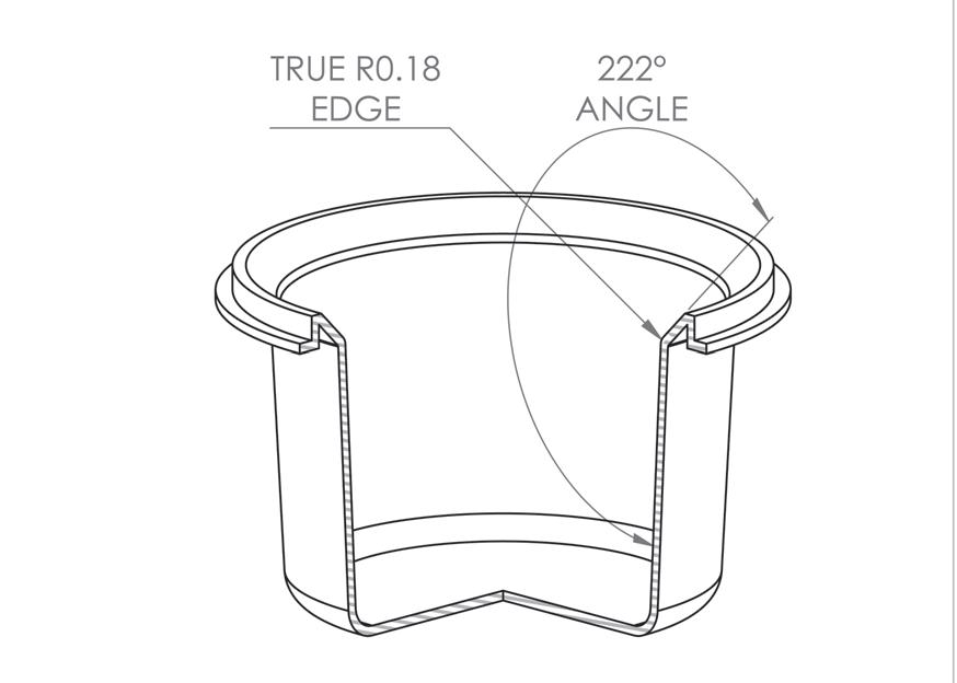
Edge: The line of intersection between any two surfaces within a SOFA flow passage aperture with an intersecting angle greater than 180 degrees, measured face to face, and having a transitional radius between the two faces of less than 0.75 in. (19 mm). Refer to Figure 1.
Figure 1: Edge
Blockable SOFA: A suction outlet fitting assembly that is not unblockable.
Body blocking element (BBE): A simulated human torso as defined in paragraph 6.2.2.
Circulation system: The materials and equipment used to collect and return water to the pool
Component: A part in a suction outlet fitting assembly (SOFA).
Cover/grate: The component of the SOFA that separates the bather from the suction outlet
Direct-suction: A method for the transfer of water from a pool where the low pressure in the SOFA is produced by a piping arrangement that is connected between the SOFA to the inlet side of a pump, or pumps, such that the piping arrangement does not include a permanently open
Existing: A pool previously installed and approved to open by the authority having jurisdiction.
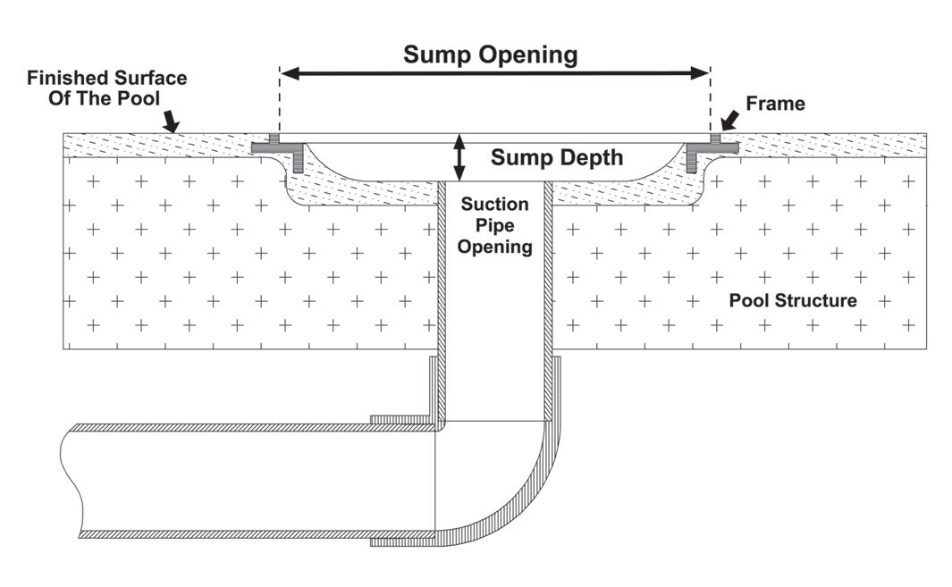
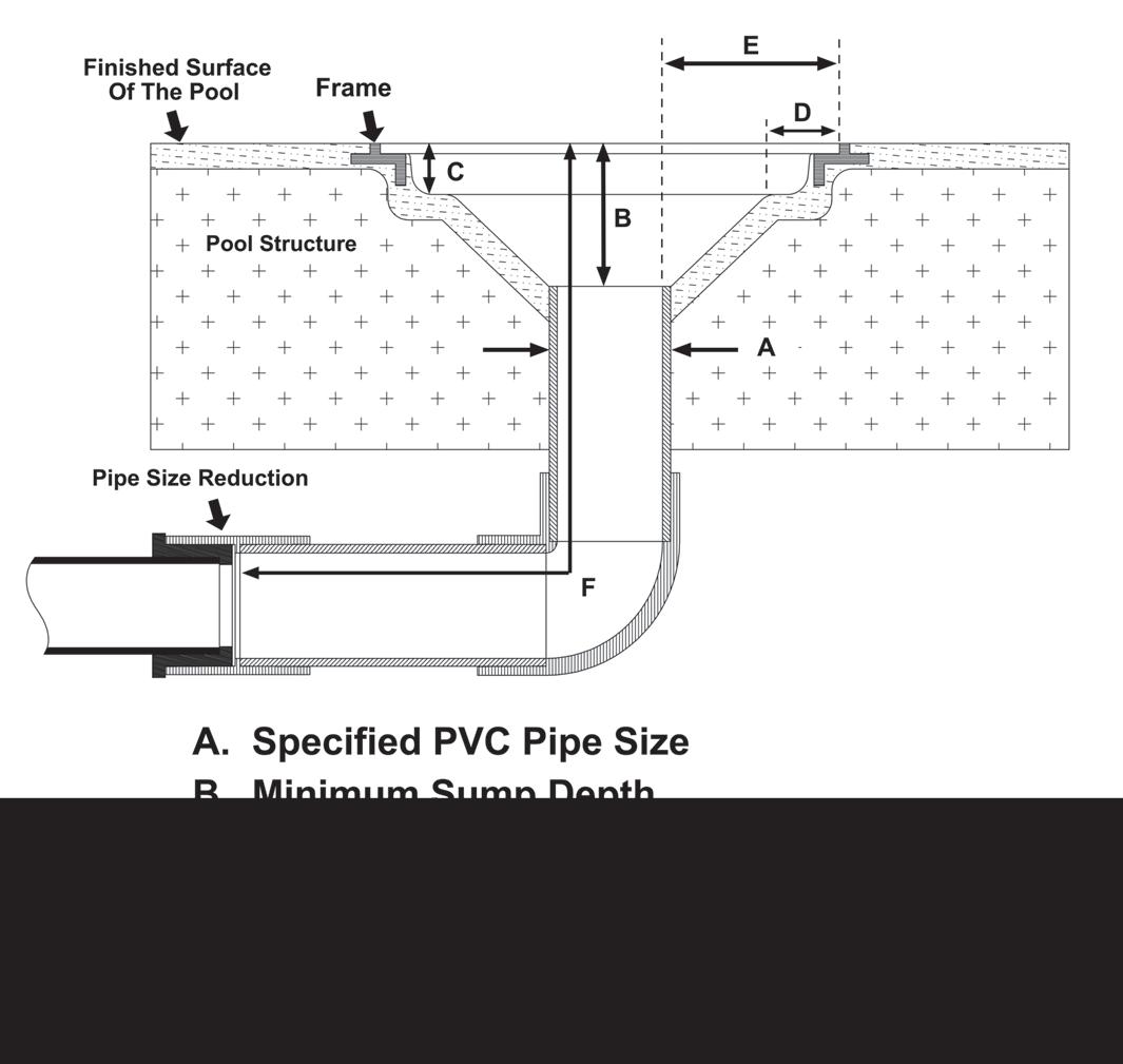
Field-built sump: A sump formed in the structure of a pool in accordance with the cover/grate manufacturer’s installation instructions, and for RDP SOFAs, in accordance with the certified plans of a registered design professional
Figure 2: Field-built sump
Finished surface of the pool: The watertight interior surface that defines the plane used to measure the distance the cover/grate protrudes into the pool, depth of the suction pipe(s) opening, and the suction port(s) opening. Refer to Figure 2.
Fire suppression water source outlet: A SOFA used to transfer water from a pool to a fire hydrant, for purposes
of using pool water to fight a fire after the pool is closed and confirmed to be clear of bathers
Floor: The structure of a pool, where a SOFA is to be installed, that is sloped between 0 degrees and 45 degrees from horizontal.
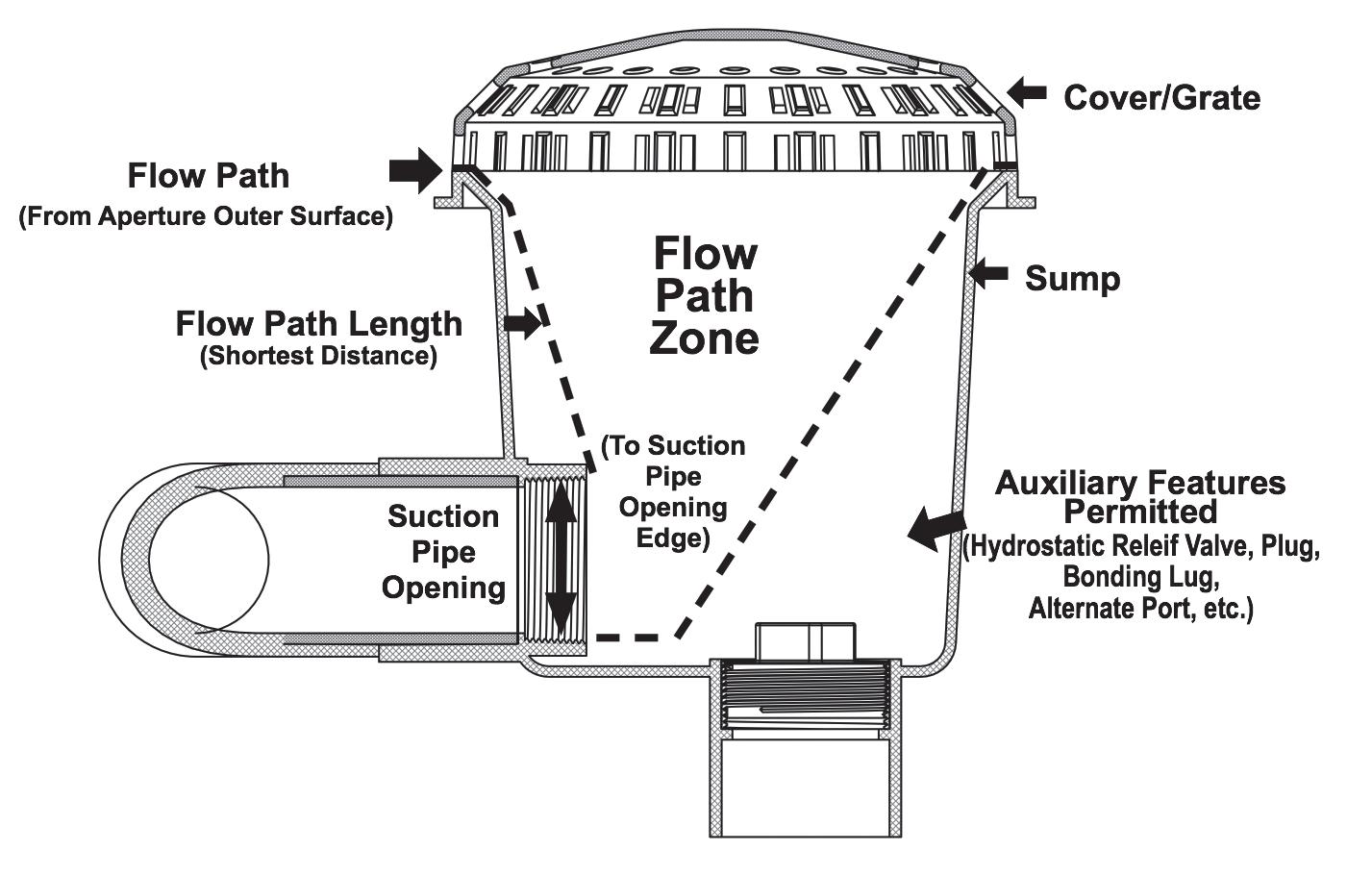
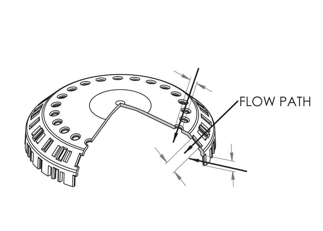
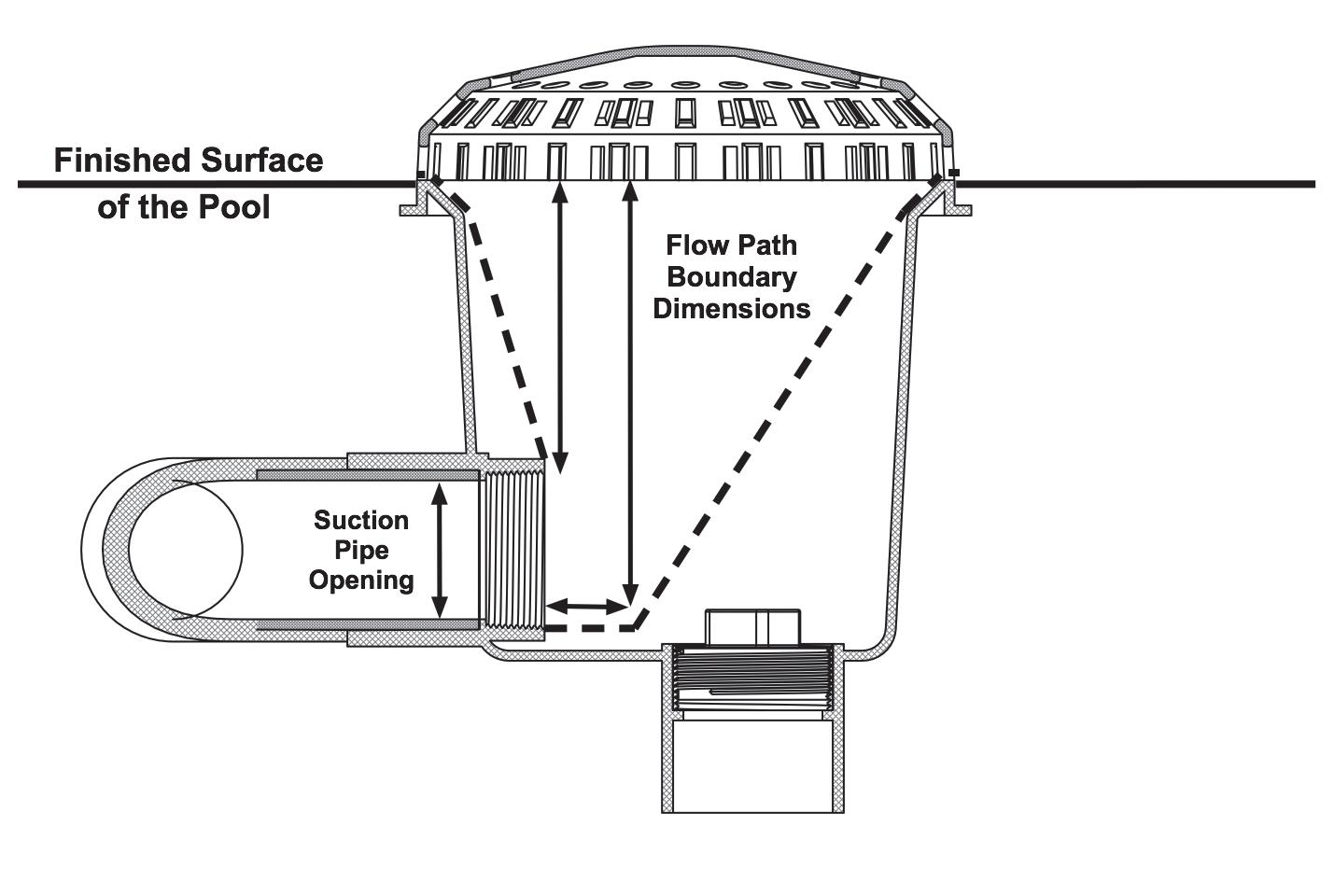
Flow path length. The shortest distance water travels between the outer surface of any cover/grate aperture and the nearest edge of the suction pipe opening. Refer to Figure 3.

flow path length used during the SOFA specific test as described in Section 5, Hair Entrapment Testing. Refer
Frame: A SOFA component that shall be structurally attached to the pool, to which a cover/grate is attached.
Fully submerged: A condition where all components of an assembly are inside the waterline perimeter and below the overflow water level of a pool.
Individual suction system flow rating: A calculation based on the quantity and type(s) of installed SOFA, where the rating is determined in accordance with the applicable paragraph 1.3.7 or 1.3.8.
Manufactured: When applied to a SOFA or SOFA component, indicates the routine commercial production of such item(s) that are evaluated for conformance to this standard in accordance with paragraph 1.3.2.1.
Main drain: A term used in VGBA to describe SOFAs.
Maintenance drain: A water outlet that is only used by maintenance personnel at times when the pool is closed and confirmed to be clear of bathers, to remove water from the pool.
Maximum system flow rate: The highest flow rate that is achievable by an individual suction system in accordance with ANSI/APSP/ICC-7.
Model number: The designation used to identify unique SOFA configurations.
Mud ring: See frame.
Multiple SOFA use only: Indicating that the referenced SOFA may be used only in conjunction with one or more additional SOFA serving an individual suction system.
Multiple SOFA system: Two or more SOFAs connected to an individual suction system.
Open area: The area available for water flow through or under a SOFA cover/grate, as measured parallel to the
Grate: An assembly, or panel with multiple openings in its surface. The term is not used in this standard to avoid confusion. See also cover/grate.
Indirect-suction: A method for the transfer of water from the pool to the inlet side of a pump(s) where the low pressure in the SOFA is produced by a difference in water levels between the pool water’s surface and a separate water vessel that includes a permanent connection to atmosphere, the opening of which is located above the overflow level of the pool. e.g., gravity flow and vent systems.
Individual suction system: A direct-suction or indirectsuction system that connects one or more SOFAs to one or more pumps, the combination of which is used to determine the maximum system flow rating of the individual suction system
Operational day: One day of use of a pool by bathers.
Part number. The designation used to identify individual SOFA components.
Pinch point: Any location within a SOFA aperture that enlarges upstream and downstream.
Permanent: Never changing, or not expected to change. e.g. piping below a pool
Pool: Any outdoor or indoor structure intended for swimming or recreational bathing, including inground
and onground structures, and includes hot tubs, spas, portable spas, infinity edge catch basins, slide and other amusement termination basins, and non-portable wading pools.
Pool owner: The person(s) recognized by the law as having the ultimate control over, and responsibility for the property on which a pool is located.
Product specifications: Information specific to a product, including, but not limited to model numbers, flow ratings, service life, SOFA type, etc., that is made available by the manufacturer or Registered Design Professional in advance of the product being sold and installed.
Q: Volumetric flow rate in cubic feet per second (ft3/s).
Registered design professional: An individual who is registered or licensed to practice their design profession, as defined by the statutory requirements of the professional registration laws of the state or jurisdiction in which the project is to be constructed.
Registered Design Professional (RDP) SOFAs: A SOFA designed and certified as conforming to all applicable requirements of this standard by a registered design professional that is custom-made for a specific pool at the construction site, or custom-made for a specific pool at a facility not normally engaged in SOFA manufacturing
Restricted use. A SOFA type that is only certified for used in a specific pool type, e.g., self-contained factorymanufactured spa, or that is distributed exclusively as a component of a manufactured, individual suction system, e.g., Venturi SOFA.
Self-contained factory-manufactured spa: A spa that is certified in conformance with ANSI/UL 1563.
Skimmers that are not fully submerged are not SOFAs; therefore, they are excluded from testing and certification to this standard.
SOFA configuration: A manufacturer or registered design professional specified assembly where any difference in mounting orientation (wall or floor), suction pipe opening size, or suction pipe opening orientation (horizontal or vertical exit from the sump) results in a different SOFA model number.
Suction outlet: Any appurtenance that provides a localized low-pressure area for the transfer of water from a pool to an individual suction system, e.g. SOFA, skimmer, gutter overflow, etc.
Self-contained spa SOFA: See paragraph 1.2.3.
Service life: The period of time between the installation of a component in a pool, with or without water at the time of installation, and the end of its useful life as specified in conformance with paragraph 3.1.1.
Shadow: That portion of a SOFA sump that is hidden by the body-blocking element (BBE) to a person viewing perpendicularly to the mounting surface of the SOFA sump.
Sharp edge: An edge that can cause a cut-type injury when contacted during normal use by a bather. Refer to UL 1439 Standard for Tests of Sharpness on Edges of Equipment.
Skimmer: A partially submerged suction outlet that is designed to remove water from the surface of a pool
Suction outlet fitting assembly (SOFA): All components, including the cover/grate, used to attach a cover/grate(s) to the finished surface of a pool and to an individual suction system
Suction pipe: A pipe used to convey water to an individual suction system.
Suction pipe opening: The inside diameter of suction pipe, suction port fitting, or other geometry through which water will flow exiting a sump.
Suction port: The portion of a SOFA sump used to connect the SOFA directly to the suction pipe.
Suction system flow rating: The maximum flow for which an individual suction system is permitted to operate while remaining in compliance with this standard.
Sump: The vessel between the suction outlet cover/grate and suction outlet piping. This may be manufactured or field-built.
Swim jet combination SOFA: A manufactured inlet/outlet SOFA that combines a suction port(s) and return port(s) into one suction outlet fitting assembly.
Total dynamic head (TDH): The total equivalent height that pool water is to be pumped, considering friction losses in the pipe. This term, along with flow rate, is used to specify the expected performance of a pool pump over its operating range, expressed as a curve plotted against head pressure versus flow rate.
Unblockable SOFA: A suction outlet fitting assembly that, when installed according to the manufacturer’s instructions, cannot be shadowed by an 18 in. x 23 in. (457 mm x 584 mm) Body Blocking Element, and has a rated flow through the remaining open area beyond the shadowed portion that cannot create a suction force in excess of the force calculated in Equation 2.
Vacuum connection cover: A cover over a fitting in the wall of a pool intended to provide a hose connection point for suction-side cleaners.
Venturi SOFA: A restricted use, blockable SOFA distributed exclusively as a component of a water-driven suction system that returns all water to the pool without it passing through a pump.
Virginia Graeme Baker Pool & Spa Safety Act (VGBA): The federal law enacted by Congress and signed by the President on December 19, 2007. Designed to prevent suction entrapments in pools, the law became effective on December 19, 2008.
Wall: The structure of a pool, where a SOFA is to be installed, that is sloped more than 45 degrees and less than or equal to 90 degrees from horizontal.
SOFAs shall be designed and installed to reduce the potential for hair, body, finger and limb entrapment.
3.1.1 Service life designation. Manufacturers and registered design professionals shall state the installed service life in years for each SOFA component.
3.1.2 Protrusion. SOFAs shall be designed such that when installed, they do not protrude more than 2 in. (51 mm) from the finished surface of the pool.
3.1.3 Sharp edges. There shall be no bather-accessible sharp edges, as defined by UL 1439 Standard for Tests of Sharpness on Edges of Equipment, on fully assembled SOFAs.
verify that the existing attachment points meet the manufacturer’s requirements.
3.1.6 Fastener compliance. All threaded fasteners joining SOFA components that are bather-accessible shall comply with all requirements of this section.
3.1.7 Fastener removability. Fasteners, excluding threaded inserts or anchors, shall be removable from the sump and any permanent SOFA components, including but not limited to, frames, mud rings, and support beams, for winterizing or replacement.
3.1.8 Permitted fasteners. When threaded fasteners are used to secure SOFA components, machine screws with associated metallic inserts or self-tapping screws shall be permitted.
3.1.9 Corrosion resistance. Metal screws shall be passivated stainless steel meeting ASTM A967 and UNS S31600 or SAE Type 316, or be made from equivalent corrosion resistant material. Metal-threaded inserts shall be made from copper alloy C23000, C61400, C64700, C65100 or C65500 or equivalent corrosion-resistant material.
3.1.10 Tool required. Fasteners shall not be removable without the use of a tool.
3.1.4 Accessible openings. All flow passage openings through and/or under cover/grates shall be designed and installed to reduce the potential for finger or limb entrapment. All manufactured SOFAs and all RDP SOFAs, shall be designed and installed in conformance with the requirements of Section 7, finger and limb entrapment tests.
3.1.5 Fasteners. Cover/grate manufacturers shall provide all fasteners required for the proper installation of the SOFA in accordance with the cover/grate installation instructions.
3.1.5.1 Cover/grate manufacturers shall designate if and when a cover/grate is suitable for attachment to previously installed SOFA components. When the replacement cover designation is used, installation instructions shall address how the installer is to
3.1.11 Service access. The use of adhesives or other attachment methods that prevent access to suction piping or SOFA components requiring periodic servicing is prohibited. Manufacturer’s installation instructions shall provide this compliance information.
3.1.12 Suction piping connections. Sumps that connect directly to the suction piping shall have suction ports that attach by an end connection that is dimensionally in accordance with ASTM D2466, by a threaded end connection in accordance with ASTM F1498, or by flanges dimensionally in accordance with ASME B1.20.1.
3.1.13 Suction piping requirements for self-contained spa SOFAs. The cover/grate manufacturer shall specify the suction piping to be used. Flexible PVC hose shall conform to IAPMO/ANSI Z1033. Rigid PVC pipe specification shall conform to ASTM D1785-Standard for Poly (Vinyl Chloride) (PVC) Plastic Pipe, Schedules 40, 80, and 120. The cover/grate manufacturer’s installation instructions shall provide this compliance information.
3.1.14 Metal component electrical bonding. SOFA components made of metal that will be exposed to pool water and that measure greater than 4 in. (100 mm) in any dimension shall provide a means for electrical bonding in conformance with the National Electrical Code, NFPA 70, Article 680. The bonding connection and wire shall not be
bather-accessible when the SOFA is fully assembled and installed in the pool. The bonding connection provided shall not be located within a SOFA flow path zone or where it may pose a hair entanglement/entrapment hazard, nor prevent service access to suction piping
3.1.14.1 The bonding connection and associated bonding wire shall be considered non-bather accessible when it cannot be touched by any portion of the “UL Articulate Probe” when evaluating the SOFA in accordance with Section 7, Finger and Limb Entrapment testing.
3.2.1 Product identifier. Each SOFA component part shall be assigned a part number and each SOFA configuration shall be assigned a model number.
3.2.2 Head loss curve. Cover/grate manufacturers shall provide a legible head loss curve covering the full range of flow for each SOFA model. The curve shall plot the SOFA-specific suction head loss in inches of mercury versus flow rate using data collected or confirmed in accordance with paragraph 5.4.5. The actual SOFA suction head loss curve shall be within a range of -3% to + 5% of the suction head or ± 5% of the flow rate, whichever is greater, indicated by the curve. The accuracy of the curve shall be verified at three points along the curve and include the suction head loss at approximately 20, 50 and 100 percent of the SOFA’s certified flow range. The head loss curve shall be accompanied by a description and/or illustration showing the approximate location the suction head was measured to aid pool designers calculating the total dynamic head (TDH) of a recirculation system.
of fasteners to be used and the recommended installation torque. Instructions shall also include a statement to start installation of screws by hand to ensure proper thread engagement and to prevent cross threading, and state the following: “DO NOT USE POWER TOOLS TO INSTALL FASTENERS”.
3.3.2 Replacement cover/grates for existing pools. Manufacturers of replacement cover/grates and other SOFA components intended for installation on existing pools with unknown sumps and mud frames shall provide specific replacement instructions for identifying when it is acceptable to attach the new cover/grate and how to confirm the attachment was successful.
3.3.3 Flow paths including pool surface. For cover/ grates where a portion of the flow path is formed by the interior surface of the pool, the cover/grate manufacturer’s installation instructions shall provide a method for the installer to verify the actual installation conforms to Section 7.3.
3.4 User Maintenance Instructions
All SOFA types shall be accompanied by user maintenance instructions containing all the information of this section that is applicable to the SOFA:
3.4.1 Field modifications. A statement that any field modification made to a SOFA not authorized by the manufacturer’s installation instructions shall void the SOFA certification.
3.4.2 Configuration modifications. A statement that no modification shall be made to a SOFA structure or flow path unless the new configuration has been certified as new SOFA.
3.2.3 Cover/grates used for multiple SOFA configurations. It shall be permissible to use a single cover/grate part(s) as a component of multiple SOFAs
3.2.4 “Blockable” and “Unblockable” designations. SOFAs shall be categorized as blockable or unblockable, as appropriate, by physical examination using the dimensions of the body-blocking element (BBE) of paragraph 6.2.2. If the sump opening can be completely shadowed by the body-blocking element (BBE) when viewed perpendicular to the pool mounting surface in which the SOFA is installed, it shall be categorized as blockable; those that cannot be completely shadowed shall be categorized as unblockable.
3.3 Cover/Grate Security, Fasteners, and Servicing Instructions
3.3.1 Fastener instructions. Cover/grate manufacturers shall provide installation instructions that detail the type
3.4.3 Service life. A statement that cover/grates and all other SOFA components shall be replaced at or before the end of their service life and that service life begins the month and year in which a SOFA component is installed with or without water.
3.4.4 Winterizing instructions. Cover/grate manufacturers shall provide instructions stating how to winterize manufactured SOFAs. Registered design professionals shall provide winterizing instructions stating how to winterize the RDP SOFA when the pool is in a location known to require winterizing.
3.4.5 Ser vice instr uctions. Cover/grate manufacturers shall provide service instructions, including a list of the required tools and the following:
3.4.5.1 A statement that the cover/grate, including fasteners, shall be observed for damage or tampering each operational day
3.4.5.2 A statement that missing, broken, or cracked cover/grates shall be replaced before bathers are allowed to use the pool.
3.4.5.3 A statement that loose cover/grates and associated components shall be reattached before bathers are allowed to use the pool
3.4.5.4 A statement indicating that SOFA components and fastener receptacles shall be clean and free of debris or obstructions during installation of cover/grate and fasteners.
3.4.5.5 Instructions shall indicate the proper alignment and assembly order of all SOFA components
3.4.5.6 The statement “DO NOT USE POWER TOOLS TO INSTALL FASTENERS” and to start installation of screws by hand to ensure proper thread engagement and to prevent cross threading.
3.4.5.7 A statement indicating the requirement to hand-check cover/grate for snugness to the sump/ frame after installation.
3.4.5.8 A statement indicating how to evaluate the integrity of SOFA components, including how to address color change, brittle components with chunks or pieces broken off, stripped screw holes, cracks, and if a mud ring is used, cracked or broken interior finish of the pool holding the mud ring in place.
3.4.5.9 A statement indicating that when any SOFA component is held in place by the interior finish of the pool, that surface shall be free of deterioration and voids.
hair in, under, and around the cover/grate and other SOFA components, including the suction piping itself. For this reason, the “Figure 2: Field-Built Sump” in the previous version of this standard has been revised and supplemented by Figures 3, 5 and 6.
Additionally, the standard now requires each SOFA configuration to be tested whenever a suction pipe(s) opening is positioned within reach of the hair used for certification testing. For SOFA configurations with all suction pipe openings positioned outside the reach of the test hair, the cover/grate only needs to be tested over a single, representative SOFA sump configuration with the highest flow potential.
3.4.5.10 Instructions for reinstallation or repair of damaged fasteners and corresponding receptacles either inserted, tapped, or self-threaded. Instructions shall include a description of the condition(s) indicating when it is necessary to remove the SOFA from service. Reinstallation and repair examples may include:
• Remove and replace SOFA component
• Provide additional holes to receive fasteners in a different orientation.
• Instructions for drilling new holes, including conditions when and where it is appropriate, and how to confirm proper installation in conformance with the requirements of this standard.
3.5 Flow Hazard-Related Requirements and Limitations
Sumps play an important role in addressing suction safety. Flowing water turbulence can twist and tangle
3.5.1 Sump specifications. Cover/grates shall only be installed on sump configurations authorized by the manufacturer’s installation instructions resulting in a unique SOFA configuration, with a specific certified flow rating. Manufactured or field-built sumps shall be permitted Refer to Figures 2, 3, 5 and 6.
3.5.1.1 The manufacturer’s product specifications and installation instructions, as appropriate, shall define each SOFA configuration and include the flow path zone, minimum suction pipe(s) opening depth below/behind the finish surface of the pool, pipe size, pipe orientation, and minimum suction pipe opening length before any reduction in pipe size. Refer to Figures 5 and 6.
5: Sump specifications
3.5.1.2 The manufacturer shall specify the minimum flow path zone dimensions equal to or exceeding the dimensions of the sump used during the SOFA-specific test as described in Section 5, Hair Entrapment Testing. The boundaries shall encompass the volume between cover/grate apertures and suction pipe(s) opening
defined by the SOFA-specific flow path of 1.3.7.1.
Refer to Figures 3, 4, 5 and 6.
Figure 6: Flow path zone dimensions
All applicable information and safety considerations provided in this section shall be included in the manufacturer’s product specifications and/or installation instructions, as appropriate, to assist pool designers, installers, and owners in the proper selection, installation, operation, and maintenance of products certified to this standard.
3.6.1 Installation. All SOFAs shall be installed in accordance with the manufacturer’s installation instructions, or for RDP SOFAs, in accordance with the registered design professional’s engineering plans
3.6.2 Field modifications. No modification shall be made to a SOFA structure or flow path unless the new configuration has been certified to the original SOFA.
3.6.3 Individual product flow ratings. This standard provides performance-based flow ratings for all SOFA(s). These flow limits are designed to prevent suction entrapment.
capacity of these systems shall not be included when evaluating an individual suction system flow rating.
3.6.4
3.6.4.1 The flow rating for pools with multiple, blockable SOFAs piped together in one body of water without isolation valves shall be determined by combining the flow rating of all SOFAs, minus the flow rating of one. If the flow ratings of all SOFAs are not equal, subtract the flow rating of the SOFA with the highest flow rating.
3.6.4.2 The flow rating for existing pools with a single, blockable SOFA is the flow rating of the SOFA, when also installed in conjunction with an additional device or system designed to prevent suction entrapment, where the additional device or systems is of a type listed in Section 9.4. A single, blockable SOFA in a system that does not also include one of the additional devices or systems shall result in a flow rating of zero.
3.6.4.3 The flow rating for pools with single, or multiple unblockable SOFAs shall be determined by combining the flow rating of all SOFAs piped together in one body of water.
3.6.5 Protrusion. Cover/grates, when installed, shall not protrude more than 2 in. (51 mm) from the finished surface of the pool in which the SOFA is installed.
3.6.6 Pool surface types. Manufacturer’s product specifications and installation instructions shall state the type of pool surfaces for which the SOFA is intended, e.g. concrete, vinyl lined, or composite pools.
3.6.7 Location limits. SOFAs shall not be located on seats or the backrests for seats.
3.6.3.1 Compliance with this standard requires that these SOFA-configuration specific flow ratings NOT be exceeded at any time the pool is open to bathers
3.6.3.2 Compliance with this standard requires selecting and installing a SOFA, or combination of SOFAs, such that the resulting individual suction system flow rating is greater than the pumping system’s maximum system flow rate.
It is also important to state that skimmers, gutters, and other overflow systems may not always be operational and could divert all the pump(s) flow through the SOFA suction system, therefore the flow
3.7.1 Cover/grates marked “Blockable” – for use in new pools. Blockable SOFAs shall be installed in a multiple SOFA system only.
3.7.1.1 When used in multiple-outlet systems, cover/ grates marked blockable shall be arranged such that the two outermost sumps/frames shall have a minimum separation of three feet, measured centerto-center. If they are to be installed closer than three feet center-to-center, they shall be located on two different planes, i.e., one SOFA shall be located on the pool floor, and one shall be located on a vertical wall, or one SOFA shall be located on each of two separate walls.
3.7.2 Cover/grates marked blockable – for use in existing pools. Cover/grates marked blockable installed in existing pools with single SOFA systems shall also be installed in conjunction with an additional device or system designed to prevent suction entrapment, where the additional device or systems is of a type listed in Section 9.4.
3.7.3 Unblockable SOFAs. Cover/grates marked unblockable are permitted for use in multiple SOFA systems, and single SOFA systems when authorized by the cover/grate manufacturer.
3.8.1 Specifications and instructions. The cover/grate manufacturer shall provide product specifications and installation instructions stating:
3.8.1.1 Self-contained spa SOFAs shall be used only in self-contained factory-manufactured spas tested and certified in accordance with ANSI/UL 1563.
3.8.1.2 Self-contained spa SOFAs shall be installed into the body or shell of the spa at the time that the spa is manufactured.
3.8.1.3 At least two self-contained spa SOFAs shall be piped so that water is drawn through them simultaneously through a common line to the related pump(s). The use of valves or fittings capable of isolating one self-contained spa SOFA from any other on the common line to the related pump is prohibited.
3.8.1.4 Self-contained spa SOFAs shall be connected to a tee leading to the pump utilizing only the SOFA manufacturer’s specified size(s) of PVC hose or pipe.
where:
aB = largest area of the cover/grate flow path openings in ft2, that can be shadowed by the body blocking element (BBE).
aR = area of the cover/grate flow path openings, in ft2, that remains unblocked
C = flow coefficient based on the design of the flow path openings in the cover/grate. It shall be based upon the actual loss coefficient of the cover/grate or representative sample from laboratory test data, unless otherwise demonstrated by calculation or test.
3.8.1.5 The maximum hose length difference between any self-contained spa SOFA and the tee leading to the pump shall not exceed 13 feet (3.96 m).
3.8.1.6 The suction pipe size between self-contained spa SOFAs shall be specified for each SOFA model.
3.9.1 Body entrapment flow rating methods. RDP SOFAs shall be rated by the body entrapment test of Section 6, or the following formulas, which shall yield the maximum allowable flow, Q, through the cover/grate. All calculations involve the open area of the cover/grate only.
3.9.1.1 Entrapping Force Criterion for Q
F = 120 lbf (534 N)
Q = limiting flow rate in ft3/s based on the allowable entrapping force
ρ = density of water.
3.9.1.2 The maximum flow rating of the SOFA in cubic feet per second (ft3/s) is Q.
3.9.1.3 The maximum flow rating of the cover/grate in gallons per minute (gal/min) is Q multiplied by 7.48 gal/ft3 multiplied by 60 s/min.
3.9.2 Water velocity limit through cover/grate. RDP SOFAs are limited to a flow velocity of 1.5 ft/sec (0.46 m/s) through any remaining cover/grate aperture not shadowed by the body blocking element of Figure 17, unless rated at a lower flow rate by a registered design professional
3.9.3 Control of flow through cover/grate RDP SOFAs shall have a sump below or behind the cover/grate of a design provided by a registered design professional documented to control flow through the open area of the cover/grate such that the design does not exceed the water velocity limits of paragraph 3.9.2. Refer to Figures 2, 3, 5 and 6.
3.9.4 Certification report. The design of RDP SOFAs shall be specified by a registered design professional in plans acceptable to the authority having jurisdiction (AHJ) for the specific pool and a written report addressed to the pool owner. The plans and report shall fully address the considerations used during SOFA certification and shall address all applicable requirements of sections/ paragraphs 1.2.5, 1.3, 3.1, 3.3 through 3.6, 3.6.4.3, 4.2 through 4.8, 4.10, 7, 8.5, 9.2, 9.3 through 9.7 as well as features particular to the specific site. Copyright©2017byThe
Equation 1
4.1 General
4.1.1 Test Conditions. All tests shall be conducted at an air and water temperature of 73.4 °F ± 3 °F (23 °C ± 2 °C).
4.1.2 Test Procedure. For the tests covered in this section a minimum of six cover/grates shall be tested in each test condition, unless otherwise stated. If the parts are made in different mold cavities, representative samples shall be taken from different mold cavities.
4.1.3 Test fixture. The SOFA shall be installed in a rigid fixture that can support the cover/grate in a manner simulating the actual installation.
4.1.4 Conditioning. All specimens shall be kept at a temperature of 73.4 °F ± 3 °F (23 °C ± 2 °C) for at least 24 hours before testing.
4.1.5 Crack detection. After each physical test, the cover/grate shall be washed, rinsed with potable water, and dried prior to application of ink. After inking, the cover/grate shall be visually inspected in accordance with paragraph 4.1.7.
4.1.6 Inking procedure. The exposed surfaces of the cover/grate, as if installed in a pool, shall be rubbed with a sponge and a 50% solution of potable water and water-soluble contrasting color ink after the unit has been washed and dried. The ink shall be rinsed from the surface with potable water, and the cover/grate allowed to air dry before inspection.
4.1.7 Inspection method. The exposed surfaces of the cover/grate, as if installed in a pool, shall be inspected for defects without the use of visual aids, except for corrective lenses, from between 1 ft. and 2 ft. (305 mm and 610 mm). The light source shall be equivalent to an illuminance near the surface to be inspected of 150 fc ± 50 fc (1615 lx ± 540 lx).
Either of two test methods shall be utilized to test for ultraviolet light degradation testing. Test Method 1 is suited for products small enough to fit into an ultraviolet (UV) test chamber, while Test Method 2 is suitable for all products.
If Test Method 1 is used, then the ultraviolet test and the structural tests are performed on fully assembled SOFAs.
If Test Method 2 is used, then the ultraviolet test is performed on two sets of “dog bone” samples molded per ASTM D638 from the same resin as the cover/grate. Set A is not exposed to UV light. Set B is exposed to UV light. In addition, all the applicable structural tests described in sections 4.3 through 4.8 are also performed on the as-sold samples. The performance requirements for those tests, however, shall be adjusted per paragraph 4.2.2.3.
Sumps and other SOFA components that are not exposed to direct sunlight when fully assembled and installed, per the cover/grate manufacturer’s installation instructions, shall not be required to meet the requirements of this section.
4.2.1 Test Method 1. Twelve new cover/grates shall be exposed to ultraviolet light and water spray in accordance with 4.2.1.1, 4.2.1.2, 4.2.1.3, or 4.2.1.4 and 4.2.1.5 through 4.2.1.7:
4.2.1.1 720 hr. of twin enclosed carbon-arc (ASTM G153, Table X1.1 Cycle 1 except the Black Panel Temperature shall be 50 °C), or;
4.2.1.2 720 hr. of twin enclosed carbon-arc (ASTM G153, a programmed cycle of 20 minutes consisting of a 17-minute light exposure and a 3-minute exposure to water spray with light shall be used with a blackpanel temperature of 63 ± 3 °C), or;
4.2.1.3 1,000 hr. of xenon-arc (ASTM G155, Table X3.1 Cycle 1 except the Black Panel Temperature should be 50 °C), or;
4.1.8 Performance requirement. The fitting shall be free from cracks as determined by inspection in accordance with paragraph 4.1.7. The presence of seams, flow lines, and knit lines shall be permitted and shall not be considered to be cracks.
4.2
Polymeric materials, including fiberglass-reinforced plastics, used for the manufacture of cover/grates and other SOFA components that may be exposed to direct sunlight when installed in a pool shall meet the requirements of this section.
4.2.1.4 750 hr. of fluorescent (ASTM G154, Table X 2.1 Cycle 1 except the 8-hour UV shall be at a Black Panel Temperature of 50 °C and the 4-hour condensation Black Panel Temperature shall be 40 °C).
4.2.1.5 Cover/grates shall be mounted inside the test apparatus, with surfaces of the cover/grate that will be exposed after installation in a pool facing the UV lamps, and positioned so they receive exposure approximating a fully assembled SOFA. After the exposure test, the cover/grates shall be removed from the test apparatus and rejected if signs of deterioration such as cracking or crazing appear. Discoloration shall
not be cause for rejection. The UV exposed samples shall then be retained under ambient temperature of 73.4 °F ± 3 °F (23 °C ± 2 °C) for not less than 16 hours, and not more than 96 hours, before being subjected to the following tests:
• Floor-Mounted Fitting Load and Deformation Test
• Wall-Mounted Fitting Load and Deformation Test
• Point Load to Excess Test
• Shear Load Test
• Pressure Differential and Point Impact Test
• Pull Load Test
4.2.1.6 The intensification factor K shall be 1.0 for UV Test Method 1.
4.2.1.7 Performance requirement. Cover/grates that were subject to the UV Test Method 1 shall comply with all applicable performance requirements of the structural integrity tests in Sections 4.3 through 4.8.
4.2.2 Test Method 2. Specimens of the component polymeric materials shall be exposed to ultraviolet light in accordance with the options specified in paragraphs 4.2.1.1, 4.2.1.2, 4.2.1.3, or 4.2.1.4, and then to the tests specified in paragraphs 4.2.2.1 and 4.2.2.2. For Test Method 2, K is derived from paragraph 4.2.2.3.
4.2.2.1 Tensile strength. Specimens of non-exposed material (A) and UV-exposed material (B) shall be evaluated for tensile strength as described in the Standard Test Method for Tensile Properties of Plastics, ANSI/ASTM D638 (ISO 527-2) using Type 1 specimens of 0.125 in. ± 0.02 in. (3.2 mm ± 0.4 mm) thickness and testing speed of 0.2 in./min ± 0.05 in./ min (5.1 mm/min ± 1.3mm/min). The tensile strength is to be that value recorded at the yield point, if the material yields, or the value at the break point if the material breaks.
4.3
integrity tests described in Sections 4.3 through 4.8 shall be conducted using non-UV exposed cover/ grates attached to a SOFA at loadings equal to the base values multiplied by the intensification factor, K. For example, if 80% of the tensile strength is retained in paragraph 4.2.2.1, and 85% of the Izod unit energy measured in paragraph 4.2.2.2 is retained, then K =1/0.80 = 1.25.
This test applies only to SOFAs intended for installation on the floor. Six cover/grates attached to a SOFA shall be tested at four locations. A point load machine readable to, at a minimum, 5 lbf (22 N) increments, and that is equipped with a steel tup of 2 in. (51 mm) minimum diameter, with a 2 in. ± 0.5 in (51 mm ± 13 mm) radius nose. A skin pad consisting of a 0.25 in. (6.35 mm) thick buna-n rubber pad of Shore A durometer 60 ± 5 hardness shall be placed between the tup and the cover/grate being tested.
4.3.1 Test method. Cover/grates shall be from Section 4.2.1 or new covers if Test Method 2 from Section 4.2.2 are used and tested as described in 4.3.1.1 through 4.3.1.3.
4.3.1.1 Each SOFA shall be mounted on a horizontal plane.
4.3.1.2 The steel tup and pad shall apply a vertical load at a total of four different locations on the cover/ grate; two points midway between the center and edge at two points between stiffeners, if any, and at two points furthest from any support element.
4.3.1.3 Using the tup and a 2 in. (51 mm) diameter skin pad on the face of the tup, and a tup speed of 0.20 in./min to 0.25 in./min (5.1 mm/min to 6.4 mm/min), apply a load at each of the above locations until 300 lbf × K ± 10 lbf (1334 N × K ± 44 N) is reached.
4.2.2.2 Impact. Specimens of non-exposed material (A) and UV-exposed material (B) shall be evaluated for impact strength as described in Method A of the Standard Test Methods for Impact Resistance of Plastics and Electrical Insulating Materials, ASTM D256 or ISO 180, using a 0.125-in. (3.2-mm) thick specimen.
4.2.2.3 Performance requirement. Samples of the material shall retain at least 70% of the non-exposed value when the tests indicated in 4.2.2.1 and 4.2.2.2 are performed. An intensification factor K shall be defined as the inverse of the lowest retained proportion of the non-exposed value when the tests in paragraphs 4.2.2.1 and 4.2.2.2 are performed. The structural
4.3.2 Performance requirement. Cover/grates and their SOFA support components shall not crack, or lose any material from the fitting, exclusive of plating or finish coatings.
4.4
This test applies to cover/grates intended for installation on a wall. Six cover/grates shall be tested and they shall be those from Section 4.2.1 or new covers if Test method 2 from Section 4.2.2 are used.
4.4.1 Test method. The tests described in section 4.3.1 shall be performed with a load of 150 lbf. × K ± 5 lbf (667 N × K ± 22 N).
4.4.2 Performance requirement. The test specimens shall meet the performance requirements of section 4.3.2.
4.5 Point Load to Excess Test
The cover/grates to be tested shall be the six previously tested in Sections 4.3 or 4.4, as applicable, with loads applied in accordance with Section 4.3.
4.5.1 Test method. The test equipment set-up and cover/grate mounting shall be as described in section 4.3. The SOFAs shall be subjected to loading at a tup speed of 0.20 in./min to 0.25 in./min (5.1 mm/min to 6.4 mm/min) until the tup protrudes through the cover/ grate, or until a value of 600 lbf × K ± 10 lbf (2669 N × K ± 44 N) is reached.
4.5.2 Performance requirement. Cover/grates shall not sustain loss of any material from the fitting, exclusive of plating or finish. Permanent deformation shall not be considered a failure.
4.6 Shear Load Test on the Horizontal Edge of Wall Mounted Cover/Grate
This test shall be applied to any cover/grate that protrudes 0.5 inch (13 mm) or more from the finished surface of the pool wall when installed per the manufacturer’s installation instructions. The six cover/ grates to be tested shall be from Section 4.2.1 or new covers if Test Method 2 from Section 4.2.2 are used.
4.6.1 Test method. Each cover/grate shall be attached to a SOFA that is mounted in a manner simulating an actual installation as closely as possible. The loads transferred from the cover/grate to the rest of the SOFA and thence to the foundation shall represent the load paths of an actual installation.
4.6.2 Performance requirement. The cover/grate shall remain in place and not crack, or lose any material exclusive of plating or finish.
The cover/grates to be tested in this section shall be the six previously tested in Section 4.6.
4.7.1 Test method. Each cover/grate shall be mounted in a manner simulating an actual installation as closely as possible. The loads transferred from the cover/grate to the rest of the SOFA and thence to the foundation shall represent the load paths of an actual installation. Pressure or vacuum may be used to develop the differential pressure that is required, the magnitude of which is determined by the value of K.
4.6.1.1 The cover/grates shall be tested by the application of a 150 lbf × K ± 5 lbf (667 N × K ± 22 N) test load applied 30 degrees from the mounting plane.
4.6.1.2 The test load shall be applied by a steel plate that is 1/2 in. × 2 in. × 2 in. (12 mm × 51 mm × 51 mm), that is covered on its face with a 2 in. × 2 in. (51 mm × 51 mm) skin pad, as defined in Section 4.3.
4.6.1.3 The six cover/grates shall be tested using the point load apparatus described in Section 4.3.
4.6.1.4 Three cover/grates shall be tested with the load placed directly in line with the fasteners.
4.6.1.5 Three cover/grates shall be tested with the load midway between fasteners, when used.
4.7.1.1 The cover/grate shall be covered with a 20-mil (0.5 mm) plastic material or other suitable material.
4.7.1.2 The cover/grate shall be subjected to an external differential pressure of 28.5 inHg × K ± 1 inHg (724 mmHg × K ± 25 mmHg) differential pressure within 60 s ± 5 s.
4.7.1.3 The differential pressure shall be sustained for 5 min ± 10 s.
4.7.1.4 The vacuum or pressure shall be removed from the system, the plastic film shall be removed, and the cover/grate shall be impacted at 15 ft-lbf × K (20.3 J × K) using the test method in ASTM D2444, with a 5 lbm. (2.3 kg) steel tup, 2 in. (51 mm) minimum diameter with a 2 in. ± 1/2 in. (51 mm ± 13 mm) radius nose.
4.7.1.5 The tup shall be dropped onto the center of the fitting from 3 ft. × K (914 mm × K).
4.7.1.6 The cover/grate shall again be subjected to the 28.5 inHg × K ± 1 inHg (724 mmHg × K ± 25 mmHg) differential pressure within 60 s ± 5 s.
4.7.1.7 The differential pressure shall be sustained for an additional 5 min ± 10 s.
4.7.1.8 Remove the sample from the test fixture, and then apply water-soluble contrasting ink in accordance with paragraphs 4.1.5 through 4.1.8.
4.7.1.9 The components shall then be inspected for cracks, breaks, or fractures in accordance with paragraph 4.1.7.
4.7.2 Performance requirement
4.7.2.1 The cover/grate shall remain in place after the test procedures in paragraphs 4.7.1.1 through 4.7.1.7.
4.7.2.2 The components shall not permanently deform, crack, or lose any material from the fitting, exclusive of plating or finish.
Pull Load Testing shall be required of all cover/grates with openings with at least two dimensions of 0.375 in. (9.53 mm) or greater. The cover/grates to be tested shall be the six previously tested in Section 4.7.
4.8.1 Test method. The cover/grate shall be installed on a SOFA per the manufacturer’s installation instructions. A total force of 150 lbf × K ± 5 lbf (667 N × K ± 22 N) shall be applied to the underside of the cover/grate, and perpendicular to the mounting surface, in locations that will approximate the load bearing points available to a bather’s finger(s). The test shall be conducted once adjacent to fasteners, and conducted once midway between adjacent fasteners. The test apparatus used shall apply an equal load to each bearing location.
4.8.2 Performance requirement
4.8.2.1 The cover/grate shall withstand a 150 lbf × K (667 N × K) pulling force.
4.8.2.2 Distortion under load shall not compromise the fastener(s), loosen the cover/grate, or cause permanent deformation exceeding 0.03 in. (0.76 mm). Metal cover/grates are exempt from the deformation requirements.
4.8.2.3 The cover/grate shall be free from cracks as determined by inspection in accordance with paragraph 4.1.7.
4.10.1.2 A torque-limiting driver shall be used.
4.10.1.3 The test shall be performed on a SOFA assembled per the manufacturer’s instructions.
4.10.1.4 The screws shall be removed manually and started manually each time.
4.10.1.5 The screws and receptacle shall be at a temperature of 73.4 °F ± 3 °F (23 °C ± 2 °C).
4.10.1.6 The use of multiple screws shall be permitted to complete this test.
4.9.1 High ambient temperatures. One sample, non-UV exposed cover/grate, assembled with any other SOFA component(s) as intended for shipping and distribution, shall be placed in a full draft circulating air oven maintained at a uniform temperature of 140 °F ± 3 °F (60 °C ± 2 °C). The sample shall remain in the oven for 7 hrs. and then be allowed to return to room temperature before being assembled and installed in the SOFA mounting surface.
4.9.2 Test sample. This sample shall be used for the Hair Entrapment Tests, Section 5, and Body Entrapment Tests, Section 6.
4.10.1 Female receptacle. Each female thread or thread receptacle shall be tested to the maximum torque specified by the manufacturer.
4.10.1.1 The test shall be performed 15 times.
4.10.2 Performance Requirement. The female receptacle shall not strip or crack, and the fastener head shall not cause cracking of the cover/grate. Threaded inserts shall not strip, twist, or pull out of the SOFA component.
The objective of this section is to measure the removal force of hair that may be drawn into a SOFA and manufacturer-specified suction pipe opening.
5.1.1 General performance requirement. Hair drawn into or onto suction fittings shall not prevent the escape of a bather in accordance with the performance requirements of Section 5.10.
5.1.2 RDP SOFAs. Hair entrapment tests are not required for RDP SOFAs certified by a registered design professional in conformance with Section 3.9.
Two types of hair shall be used in this test. Separate tests shall be run with each hair type.
5.2.1 Type 1, (skull). A full head of natural, fine, straight, blond European, human hair with cuticle on hair stems, 16 in. (406 mm) in length, weighing 5.5 oz. ± 0.5 oz. (155 g ± 15 g), shall be firmly affixed to a simulated skull with a head circumference of 22.8 in. ± 1 in. (579 mm ± 25 mm), a head length of 7.9 in. ± ½ in. (201 mm ± 13 mm), and a head breadth of 6.2 in. ± ½ in. (157 mm ± 13 mm) in a manner approximating the normal distribution of hair. The completed assembly shall weigh between 1 pound (454 g) and 2 pounds (907 g) when submerged at the test depth. An anchoring point shall be provided near the neck of the simulated skull. Hair shall be trimmed evenly to a length of 16 in. (406 mm) ± ¼ in. (6 mm), measured from the top of the skull, after being attached to the simulated skull.
5.2.2 Type 2, (ponytail). Natural, medium-to-fine, lightbrown colored human hair weighing 2 oz. ± 0.11 oz. (57 g ± 3 g) and having a length of 16 in. (406 mm) shall be
affixed to a 1 in. (25 mm) diameter by 12 in. (305 mm) or longer wooden dowel, as may be required to properly place the hair sample for testing. Consideration shall be given to the buoyancy of the portion of the wooden dowel more than 12 in. (305 mm) in determining the removal force. A method for attaching a scale shall be provided on the opposite end of the dowel. Hair shall be trimmed evenly to a length of 16 in. (406 mm) ± ¼ inch (6 mm) measured from hair attachment end of the dowel.
5.3.1 Water temperature. During all tests, the water shall be at a temperature at 90 °F ± 10 °F (32°C ± 6 °C)
5.3.2 Water depth. During all tests and with water flowing, the minimum water level of the tank shall be above the shallowest cover/grate flow passages such that the hair test assembly, up to and including the pull mechanism attachment point of the skull or ponytail, is at least 2 in. (51 mm) below the water level. Refer to Figure 7.
5.3.3 Water currents. Influences of water currents shall be virtually absent in the test tank, as evidenced by the
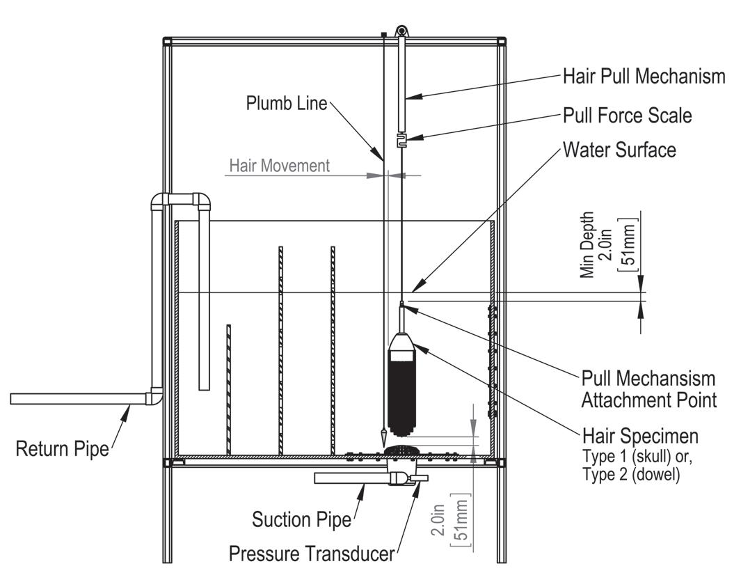
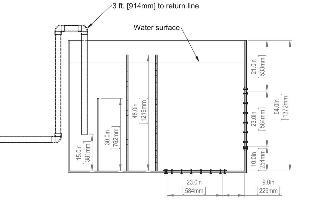
5.3.4 Optional test tank. The test tank for evaluation of the SOFA for the hair entrapment test shall comply with Figures 8 and 9. The baffle plates shall be constructed as shown in Figures 10 and 11.
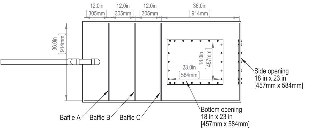
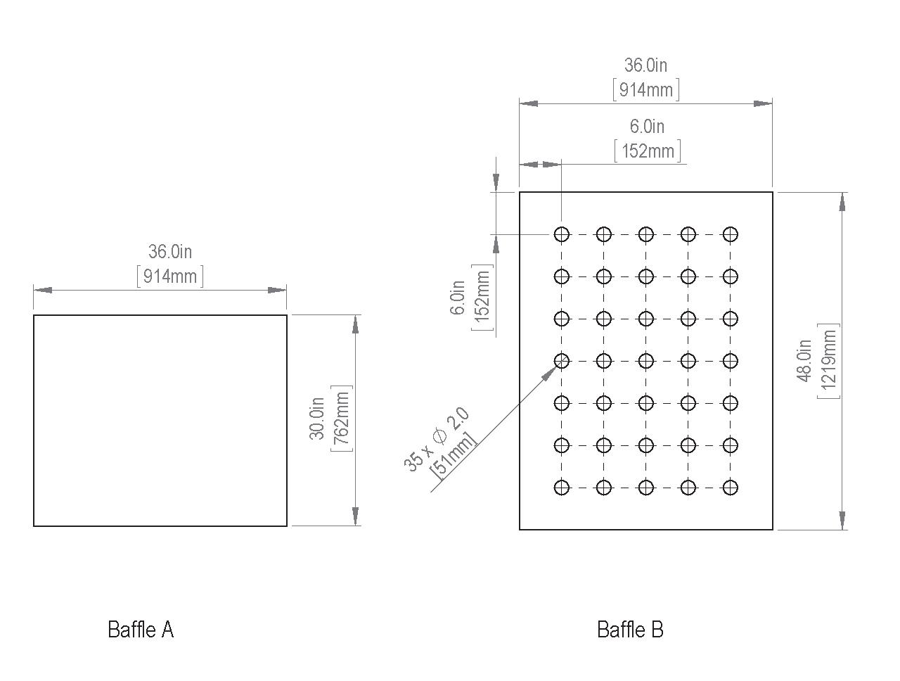
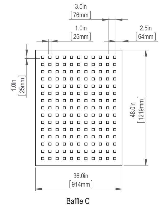
5.3.5 Alternate test tanks
5.3.5.1 The same tank as described in paragraph 5.3.4, with Baffle C, bottom, sides, and only the one end where the fittings are tested may be used by inserting the tank into a larger body of water so that the submerged depth of the simulated SOFA mounting surface is the same as in paragraph 5.3.2.
5.3.5.2 The volume of the water in this larger body of water shall substitute for the return line piping depicted in Figures 7, 8 and 9.
5.3.5.3 Any other body of water may be used if the body of water provides equivalent test results as intended by this standard.
5.4.1 Pump flow. The pump shall be capable of producing a flow rate at least 25% greater than the cover/grate manufacturer’s anticipated rating of the SOFA configuration
5.4.5 SOFA suction. The suction head shall be measured with a pressure transducer or sensing device with an operating range appropriate for the test and with a minimum accuracy of 1% full scale. The elevation of the pressure sensor diaphragm or strain gauge above or below the water level of the test tank, as measured during the test, shall be recorded, and the value shall be adjusted as required to correct for positive or negative water column. The maximum suction head reading (corrected for elevation) shall be recorded.
5.4.2 Flow measurement. A flow meter with an accuracy of ±3% at the anticipated SOFA configuration rating shall be installed in the piping system in accordance with the flow meter manufacturer’s installation instructions.
5.4.3 Flow control. A valve shall be used to adjust the test flow rate. Altering the speed of the pump motor shall not be used to vary the test flow rate.
5.4.4 Pump suction. The suction source for the hair and body entrapment tests shall be a pumping system that is capable of producing the required volumetric flow rate, and a suction head of at least 26.0 inHg, measured as close as practicable to the SOFA in accordance with paragraph 5.4.5, when the suction piping is completely blocked after the discharge is throttled to deliver the test flow rate. Refer to Figures 7 and 12.
5.4.6 Hair pull mechanism. A pull mechanism with an anchoring point located directly above the area of the SOFA being tested, such that during any test, the hair specimen will be pulled vertically towards the surface of the water. It shall be capable of maintaining a consistent speed of 5 in/s ± 0.25 in/s (127 mm/s ± 6 mm/s) when pulling either the Type 1 (skull) or Type 2 (ponytail) hair specimen. Refer to Figure 7.
5.4.7 Pull force measurement. A scale accurate to ±0.1 lbf (0.45 N) at a tension of 5 lbf (22 N) shall be used to measure the hair removal force.
5.5.1 Test assembly. The SOFA, including a cover/grate, as conditioned in accordance with paragraph 4.9.1 and the sump to be tested, shall be installed in accordance with the manufacturer’s installation instructions on the SOFA mounting surface, with a surface area of sufficient size such that the BBE does not touch a mounting surface edge, or associated mounting hardware. Refer to Figure 12.
specific pipe size
point of lab pipe reduction or enlargement
5.5.2 SOFA-only flow path. For assemblies where all flow passages are provided by manufactured SOFA components, the SOFA mounting surface of Figure 12 shall be planar and represent actual field practices, with smooth surfaces immediately adjoining the top edge of the frame or sump, or as specified by the manufacturer, in accordance with their installation instructions.
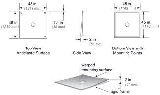
5.5.3 Pool surface flow path. For assemblies where a portion of the flow passage is the finished surface of the pool and is not controlled by the cover/grate manufacturer, the SOFA mounting surface shall represent field imperfections that may produce a hair entrapment hazard. The nominally square planar mounting surface shall be distorted to an anticlastic surface such that one corner is 2 in. (51 mm) away from a plane defined by the other three corners of a 48 in. × 48 in. (122 mm × 122 mm) square as shown in Figure 13. A convenient means shall support three of the corners in a plane with 1 in. (25 mm) clearance from the nearby surface of the frame, then force the fourth corner 2 in. (51 mm) from the plane of the first three. Supports shall be localized, and 1.5 in. (38 mm) from the edges of the mounting surface. The test specimen shall be firmly attached to the anticlastic surface in a field installation manner as specified by the cover/grate manufacturer.
5.6 Self-Contained Spa SOFA Mounting Surface, Test Position, and Piping
5.6.2 Multiple pipe sizes. When more than one size of hose/pipe is specified by the self-contained spa SOFA manufacturer’s product specifications or installation instructions, each size of hose shall be tested.
5.6.3 Hair test configuration. SOFA #1, shown in Figure 14, shall be tested for hair entrapment in accordance with Sections 5.8 through 5.10.
5.7.1 Sump dimensions. Manufacturers shall provide the test lab with the dimensions of the sump to be used during each SOFA model test. Refer to Figures 3, 5 and 6.
5.6.1 Test assembly. Self-contained spa SOFAs shall be installed in pairs on the SOFA mounting surface using 14 ft. ± 1 ft. (4267 mm ± 305 mm) of flexible PVC hose in accordance with Figure 14.
Figure 14: Self-contained spa SOFA
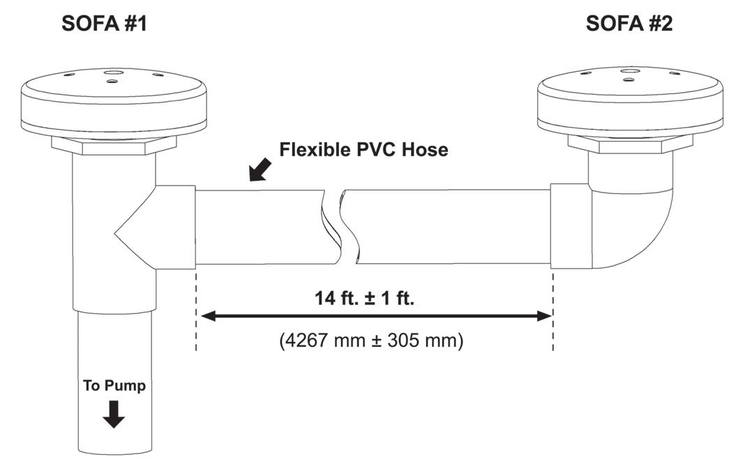
5.7.1.1 The lab shall measure and document the minimum flow path length for each SOFA model for purposes of determining the hair test scope of either 5.7.2 or 5.7.3. Refer to Figure 3.
5.7.1.2 The flow path length shall be measured using a string line from the entrance of the nearest aperture to the closest suction pipe opening to identify the shortest distance Type 1 or Type 2 hair can travel from the cover/grate to a suction pipe opening.
5.7.2 Flow path length less than 16 inches. Each SOFA model shall be tested at the minimum cover/ grate manufacturer-specified distance from the top of the pipe opening to the finished surface of the pool to simulate actual installations including each suction port combination for manufactured sumps with multiple suction ports and/or suction pipe opening sizes. These SOFA models shall be tested with a 90-degree elbow of the same size as the suction pipe opening, installed as close to the sump as practical. All suction pipe openings shall be challenged as part of Type 1 and Type 2 hair tests.
5.7.3 Flow path length equal to or greater than 16 inches. Only the SOFA configuration with the largest manufacturer-specified suction pipe opening size and suction pipe quantity, the configuration of which results in the highest flow potential for the cover/grate, shall require Type 1 and Type 2 hair tests. A 90-degree elbow of the same size as the suction pipe opening is not required when testing SOFAs with a flow path equal to or greater than 16 in. (406 mm).
5.8 SOFA Test Positions
5.8.1 Floor-mount. For SOFAs intended for floor-mounted installations, the SOFA mounting surface shall be horizontal.
5.8.2 Wall-mount. For SOFAs intended for wall-mounted installations, the SOFA mounting surface shall be vertical.
5.8.3 Wall and floor-mount. SOFAs intended for either wall or floor-mounted installations shall be tested with the SOFA mounting surface configured in both vertical and horizontal positions.
5.8.4 Non-uniform flow-path. For SOFAs intended for wall-mounted installation that have a cover/grate flowpath pattern that is not uniform, the cover/grate shall be tested in two clock positions that represent the essential geometric differences that may affect the hair removal force. Refer to Figures 15 and 16.
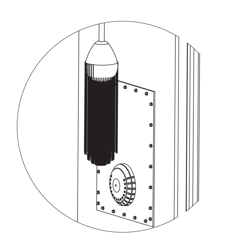
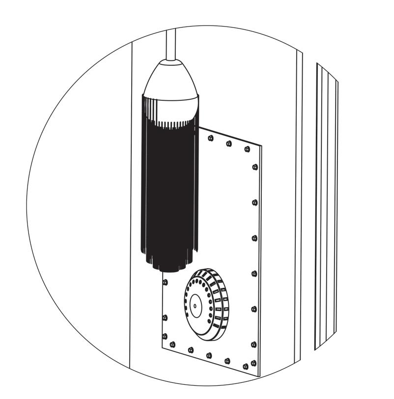
5.9
5.9.2 Pull mechanism verification. Prior to energizing the test pump, the pull mechanism shall be verified to ensure consistent speed when pulling a 2 lbm (8.9 N) and a 10 lbm (44 N) weight. For each test weight, the speed of the pull shall be 5 inches per second ± 0.25 inches per second (127 mm/s ± 6 mm/s). Refer to Figure 7.
5.9.3 Hair specimen. Test hair preparation and maintenance.
5.9.3.1 Prior to use, the hair shall be cleaned in a solution of 10% by volume of sodium alpha olefin sulfonate (AOS), and potable water. The hair test sample shall be rinsed in potable water after cleaning.
5.9.3.2 The hair shall be submerged in the test tank water for a minimum of 2 minutes prior to use.
5.9.3.3 New hair shall be conditioned by performing ten test pulls prior to recording the hair removal force.
5.9.3.4 Hair samples shall be cleaned before first use and after every ten pulls.
5.9.3.5 A fresh sample of hair shall be used when tangles in the hair cannot be removed by combing.
5.9.4 Hair Test Starting Position
5.9.4.1 The starting position of the free end of the hair for a wall-mounted SOFA shall be in front of and 2 in. (51 mm) above the SOFA, as illustrated in Figures 15 and 16.
5.9.4.2 The starting position of the free end of the hair for a floor-mounted SOFA shall be placed 2 in. (51 mm) above the area of the SOFA to be evaluated, as illustrated in Figure 7.
5.9.5 Hair test approach and hold position
5.9.5.1 The hair test shall then be uniformly moved closer to the suction portions of the fitting, as illustrated in Figure 17.
5.9.5.2 The ends of the hair shall be fed into the SOFA in the direction of the intake flow.
5.9.5.3 The hair shall be continuously fed into the SOFA while moving the skull or ponytail in a sweeping motion.
5.9.5.4 The magnitude of the sweeping motion shall be reduced with each pass of the skull or ponytail.
5.9.1 Starting flow rate. The manufacturer shall specify the starting test flow rate for each SOFA configuration to be tested.
5.9.5.5 The hair shall be moved toward the SOFA over a period of 30 seconds ±5 seconds.
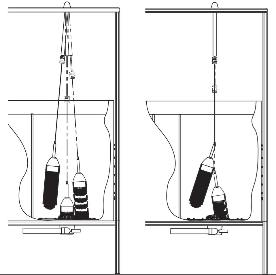
5.9.5.6 The skull or ponytail end shall be held against the cover/grate for 30 seconds ± 5 seconds.
5.9.5.7 The skull or ponytail shall then be released and allowed to float or remain free for 30 seconds ± 5 seconds.
5.9.5.8 In testing any SOFA which is not entirely symmetric, or those mounted on an anticlastic surface, testing shall start with the free end of the hair at least 2 in. (51 mm) from any portion of the fitting.
5.9.7.1 The flow rate shall be increased in 5 gpm (19 L/min) increments.
5.9.7.2 Ten tests shall be performed at each flow rate.
5.9.7.3 The hair shall be combed or brushed before each test until it is free of tangles.
5.9.7.4 The amount of force necessary to free the hair from the fitting shall be measured with the test pump(s) operating.
5.9.6.1 Hair entrapment tests for SOFAs with a flow path length less than 16 in. (406 mm); each SOFA configuration shall be tested, including each suction port combination for manufactured sumps with multiple suction ports and/or suction pipe opening sizes. Hair entrapment tests for SOFAs with a flow path length greater than 16 in. (406 mm); the SOFA configuration that results in the highest flow potential shall be tested.
5.9.6.2 The area of the cover/grate adjacent to each suction port shall be challenged with the Type 1 (skull) and Type 2 (ponytail) hair specimens.
5.9.6.3 The scale shall be reset to zero prior to each pull test, if applicable.
5.9.7.5 The skull or ponytail shall be attached to the scale and the scale shall be zeroed while the skull or ponytail is fully immersed in the test tank water.
5.9.7.6 The skull or ponytail shall be pulled vertically away from the fitting by activating the hair removal mechanism. The removal force and suction head shall be measured and recorded.
5.9.7.7 Where a failure is determined with a specific 5 gpm (19 L/min) increase, the SOFA shall be permitted to be retested in 1 gpm (3.8 L/min) increments up to the point of the previous failure.
5.10.1 Failed test. A pull of 5 lbf (22 N), or greater, on any one of the ten pulls, including the equalized weight of the saturated test apparatus, shall be deemed a failure, and the flow rate in gpm at failure shall be recorded. If only one failure in ten pulls occurs, repeat the test, with ten more pulls. If no failures occur in the second set of ten pulls, move to the next higher flow rate. The flow rate, pull force, and suction head of each passing set of tests used to determine the SOFA flow rating shall be recorded and reported.
5.10.2 Flow rating procedure. The maximum allowable certified flow rating shall be the lower of either the highest passing flow rate for any of a SOFAs suction ports, divided by 1.25, the body blocking flow rate determined in Section 6 or any lower flow rating specified by the cover/ grate manufacturer.
The objective of this section is to measure the removal force of a body that might be held against a cover/grate by the suction force of a pump.
6.1.1 Manufactured cover/grates. The body entrapment test shall apply to all manufactured cover/grates certified under this standard.
6.1.1.1 RDP SOFAs shall be certified in accordance with either Section 3.9 or Section 6.
6.1.2 Test specimen quantity. Only one cover/grate is required to be tested.
6.1.3 Single-outlet testing. Self-contained spa SOFAs shall be tested for conformance with Section 6 using a single-outlet configuration on a SOFA mounting surface in accordance with Section 5.5 and the body entrapment test shall not be performed using the configuration of paragraph 5.6.1.
Tests shall be performed using the equipment specified in paragraphs 6.2.1 through 6.2.8.
6.2.1 Test tank. A test tank in accordance with Section 5.3.
6.2.2 Body blocking element (BBE). The body-blocking element (BBE) shall be constructed of 2-in. (51 mm) thick closed-cell nitrile butadiene rubber/(poly) vinyl chloride (NBR/PVC) foam with a compression deflection value of 1.5 psi to 3.0 psi (10 kPa to 21 kPa) at 25% deflection, as measured in accordance with ASTM D105600. The foam shall be mounted to a 3⁄4 in. (19 mm) waterproofed plywood backing, with the skin side of the foam facing away from the plywood. The vertical corners of the body-blocking element (BBE) shall have a radius of 4 in. (102 mm). Refer to Figure 18.
Figure 18: Body blocking element (BBE)
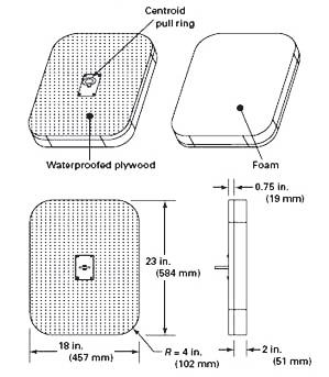
6.2.3 BBE attachment. An eyebolt, or equivalent device located at the centroid of the body blocking element (BBE), shall be used to attach the body-blocking element (BBE) to the push/pull actuator as shown in Figure 18.
6.2.4 Push/pull actuator. An apparatus that can apply 120 lbf (534 N) vertically downward and upward on the body-blocking element (BBE), release the downward force within 2 seconds, then apply the upward force required to remove the body-blocking element (BBE) from the cover/ grate
6.2.5 Push/pull force measurement. A scale accurate within 0.5 lbf (2.2 N) at a compression/tension of 120 lbf (534 N) shall be used to measure the BBE removal force.
6.2.6 SOFA test configuration. The cover/grate shall be installed on and tested with the SOFA configuration of Section 5 that provided the highest flow rating.
6.2.6.1 For SOFA’s certified for wall-only applications, the testing of Section 6 may be performed in either the vertical or horizontal orientation. When a cover/ grate certified for walls only is to be tested in the wall mounted position, the push/pull actuator performance requirements of paragraph 6.2.5 shall be met except the push/pull forces shall be applied horizontally.
6.2.7 Pumping system. Shall be in accordance with paragraph 5.4.4.
6.2.8 Buoyancy. The body-blocking element (BBE) shall be ballasted to neutral buoyancy within 0.7 lbf (3.1 N) at the test depth, and the buoyancy shall be reported.
6.3.1 Test orientation. With the cover/grate installed on the SOFA configured in accordance with paragraph 6.2.6 and with the pumping system operating in conformance with paragraph 6.2.7, the body-blocking element (BBE) shall be centered over the cover/grate and oriented to block the largest possible open area of the cover/grate
6.3.2 Applied force. A force of 120 lbf (534 N) shall be applied through the eyebolt, or equivalent, to fully seat the body-blocking element (BBE) on the cover/grate
6.3.3 Applied force timing. The applied force shall be removed from the body-blocking element (BBE) within 2 seconds.
6.3.4 Applied removal force. Within 2 seconds after removal of the applied force, the push/pull actuator shall begin to lift the body-blocking element (BBE) from the cover/grate
6.3.5 Recorded removal force. The maximum force required to remove the body-blocking element (BBE) from the cover/grate shall be recorded as the removal force.
6.4.1 Allowable removal force. Under these test conditions, the removal force shall not exceed the value specified by the equation:
Equation 2:
where:
F max = the maximum permissible removal force in pounds.
Wderived = the minimum width in inches of a rectangular shape whose length is 1.28 times the width, with corners of radius 22% of the width dimension, which completely shadows the openings of the cover/grate, and shall in no case be smaller than 9 in. (229 mm) nor larger than 18 in. (457 mm).
6.4.2 Number of tests. The maximum permissible removal force shall not be exceeded in three consecutive tests.
6.4.3 Failed test. Where a failure is determined at the tested flow rate as specified in Section 6.3, it is permitted to test the cover/grate in 5 gpm (19 L/min) decrements until it passes. Then it is permitted to retest the cover/ grate in 1 gpm (3.8 L/min) increments up to the point of failure to determine the SOFA rating under Section 6.
7.1.4 Pool surface flow path. Finger entrapment tests shall be conducted on each SOFA configuration capable of altering the size of any cover/grate aperture opening, e.g., cover/grates certified in accordance with paragraph 5.5.3.
7.1.5 Temperature. Tests shall be conducted at 73.4 °F ± 3°F (23 °C ± 2 °C) using a new, dry SOFA.
7.1.6 Test apparatus. Tests shall be conducted with the “UL Articulated Probe” in accordance with Figures 19, 20, 21 and 22.
6.4.4 Reporting test results. The maximum removal force, test flow rate, and maximum suction head shall be recorded and reported for the three passing tests.
The objective of this section is to evaluate a cover/grate for geometry that might entrap a finger or limb.
7.1 General
7.1.1 Test scope. The finger and limb entrapment test of this section shall apply to all SOFA types.
7.1.2 Test specimen. Finger entrapment tests shall be conducted on one new cover/grate.
7.1.3 Aperture size limit. When fully assembled, SOFAs shall not have any accessible opening that allows the passage of the 1 in. (25 mm) cylindrical end of the UL articulated probe.
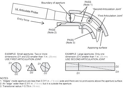
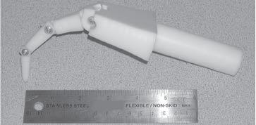
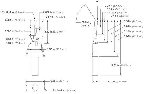
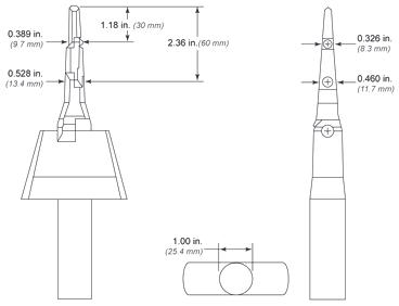
7.2 Finger and Limb Test Procedure
7.2.1 Apertures. Each flow passage aperture of the cover/grate when installed on the SOFA shall be subjected to the insertion of both ends of a “UL Articulated Probe”.
7.2.2 Applied force. The finger probe shall be inserted with a force of 3 lbf ± 0.15 lbf (12 N ± 0.6 N)
7.3 Finger and Limb Test Performance Requirement
7.3.1 Aperture size. A small or large aperture is permitted when the 1 in. (25 mm) cylindrical end of the “UL Articulated Probe” cannot be made to penetrate through to the inside surface of the aperture and as follows:
7.3.1.1 Small apertures shall be permitted when the centerline of the first articulation joint, located 1.18 in. (30 mm) from the point end of the “UL Articulated Probe”, cannot be made to pass beyond an edge or pinch point that is located inside the aperture being tested. Refer to Figures 19, 20, 21 and 22.
in. (59.9 mm) from the point end of the “UL Articulated Probe”, cannot be made to pass beyond an apposed edge or pinch point that is located inside the aperture being tested. Refer to Figures 19, 20, 21 and 22.
8.1 Cover/Grate Markings Visible When Installed
8.1.1 Visibility and content. All manufactured cover/ grates shall include markings permanently legible and located on an exposed surface that is readily visible after installation. The text font size shall be at least 0.08-in. (2.03 mm) tall and shall include the following:
8.1.1.1 The name, trade name or trademark of the manufacturer.
8.1.1.2 A distinctive part number.
8.1.1.3 The type of service, “Blockable” or “Unblockable” as appropriate.
8.1.1.4 The manufacturer specified service life in years, e.g., “Life # Years” where “#” is years.
8.1.1.5 “VGBA 2017”, where 2017 indicates the year this standard was approved by the American National Standards Institute.
8.1.1.6 Certification agency conformity markings.
8.1.2 Cover/grate flow ratings.
8.1.2.1 Single flow rating. Cover/grates with only one set of flow ratings shall be marked “Wall ### GPM”, and/or “Floor ### GPM”, or “Wall/Floor ### GPM as appropriate, where ### is the flow rating in GPM as certified in accordance with paragraph 1.3.7.
7.3.1.2 Edges and pinch points shall be permitted within the small aperture and within range of the first articulated joint in accordance with Figure 19 if they are less than 0.311 in. (7.9 mm) wide, measured parallel to the aperture opening.
7.3.1.3 Edges and pinch points created by molding lines, engraved text, and symbols shall be permitted within the small aperture provided they do not exceed a height of 0.025 in. (0.64 mm).
7.3.1.4 Large aperture(s) shall be permitted if the centerline of the second articulation joint, located 2.36
8.1.2.2 Multiple flow ratings. Cover/grates with multiple sets of flow ratings shall be marked “For Flow Ratings See Instructions” or all flow ratings shall be marked on the cover/grate in accordance with paragraph 8.1.7.1 such that flow ratings are adjacent or otherwise associated with the SOFA model number
8.1.3 Self-contained spa SOFA. This type of cover/grate shall be marked with “For Use in Self-Contained FactoryManufactured Spas Only”.
8.2 Cover/Grate Markings Not Visible When Installed
8.2.1 Manufacturing date. All manufactured cover/grate markings shall be permanently legible and located on any surface that is readily visible before or after installation. The markings shall include the following:
8.2.1.1 The date of manufacture, or period of manufacture not exceeding one month.
8.3.1 Visibility and content. All manufactured sump and mud frame markings shall be permanently legible and located on any surface that is readily visible after the part has been installed in the pool. These markings shall be permitted to be hidden when the cover/grate is installed. The text font size shall be at least 0.08-in. (2.03 mm) tall for all markings except it is permissible for the text on standard injection molding date indicators to be smaller.
8.3.1.1 The name, trade name, or trademark of the manufacturer.
8.3.1.2 A distinctive part number.
8.3.1.3 The manufacturer-specified service life in years, e.g., “Life # Years” where “#” is years.
8.3.1.4 The date of manufacture, or period of manufacture not exceeding one month.
8.4 Installation Information Label
8.4.1 Label specifications. Each manufactured cover/ grate shall be packaged with a label made from materials designed to exceed the service life of the cover/grate, and of sufficient size and format to be legibly filled-in by the installer at the time the cover/grate is installed. The manufacturer shall prefill-in the information required by paragraphs 8.4.1.1 through 8.4.1.4.
Instructions shall be provided with the label requiring the cover/grate installer to fill-in the balance of the information required by paragraphs 8.4.1.5 to 8.4.1.7 before giving the label to the pool owner. The label instructions shall request it be permanently posted as near as feasible to the pump control, and that a copy of this information be given to the pool owner, to be kept with other important pool related documents.
8.4.1.1 Manufacturer's name.
8.4.1.2 Cover/grate part number.
8.4.1.6 Location of the installed SOFA, such that it can be successfully identified in the future.
8.4.1.7 The date the cover/grate was installed in the pool, where the month and year indicators on the label are easily activated in the field.
8.5.1 RDP SOFA identification. The registered design professional that certifies an RDP SOFA shall either apply the applicable markings to the SOFA in conformance with Sections 8.1 through 8.3 and provide an information label in conformance with Section 8.4, or the equivalent information shall be posted on a permanently-mounted sign, that is adjacent to the pool circulation pump(s). When posting adjacent the pump(s) is not feasible, the sign shall be posted in the equipment area and indicate which pump(s) to which the SOFA(s) is installed. The minimum text size of the sign lettering shall be 0.33 in. (8.4 mm) tall.
Each product certified to this standard shall be provided with installation instructions, user-maintenance instructions, and important safety instructions. Installation instructions shall only include SOFA configurations that have been certified in accordance with Section 1.3.
9.1.1 The installation instructions shall include all information required by Section 3 that is applicable to the product for which these instructions are intended.
9.2.1 RDP responsibility. Registered design professionals who certify and supervise the installation of an RDP SOFA shall not be required to provide installation instructions. Those that do not supervise the installation shall provide installation instructions applicable to the specific SOFA in accordance with paragraph 9.1.1.
8.4.1.3 Service life of the cover/grate
8.4.1.4 The certified cover/grate flow rating(s), as they are permanently marked in accordance with paragraph 8.1.7.1, when applicable.
8.4.1.5 The certified flow rating specific to the SOFA configuration and installed orientation, i.e., wall or floor, for cover/grates permanently marked “For Flow Ratings See Instructions”.
The SOFA manufacturer shall provide a “General Certificate of Conformity (GCC)” with each SOFA, or instructions how to secure this information via electronic means. The GCC shall include the following information, which was current at the time this standard was approved, however manufacturers and registered design professionals shall consult CPSC.gov for current GCC requirements.
9.3.1 Identification of the product covered by this certificate: Describe the SOFA covered by this certification in enough detail to match the certificate to each product it covers and no others.
9.3.2 Citation to VGBA to which this product is being certified: The cer tificate must identify the Virginia Graeme Baker Pool and Spa Safety Act, the consumer product safety rule that is applicable to SOFAs.
9.3.3 Identification of the U.S. importer or domestic manufacturer certifying compliance of the product: Provide the name, full mailing address, and telephone number of the importer or U.S. domestic manufacturer certifying the product.
9.3.4 Contact information for the individual maintaining records of test results: Provide the name, full mailing address, e-mail address, and telephone number of the person maintaining test records in support of the certification.
9.3.5 Date and place where this product was manufactured: For the date(s) when the product was manufactured, provide at least the month and year. For the place of manufacture provide at least the city (or administrative region) and country where the product was manufactured or finally assembled. If the same manufacturer operates more than one location in the same city, provide the street address of the factory.
9.3.6 Provide the date(s) and place when the product was tested for compliance with this standard: Provide the location(s) of the testing and the date(s) of the test(s) or test report(s) on which certification is being based.
9.3.7 Identification of any third-party laboratory on whose testing the certificate depends.
9.4.1.2 SUCTION-LIMITING VENT SYSTEM- A circulation system that incorporates a tamper-resistant atmospheric vent that is hydraulically located between the suction outlet and the circulation pump, which allows air to enter the circulation system and release the vacuum within the system when the suction outlet is blocked and the circulation pump is operating.
9.4.1.3 GRAVITY DRAINAGE SYSTEM- A powered circulation system, which utilizes a collector tank hydraulically located between the pump and the suction outlet that is filled by the gravitationally induced flow of water from the suction outlet, and is vented to the atmosphere by a tamper-resistant opening.
9.4 VGBA Devices and Systems Designed to Prevent Suction Entrapment
9.4.1 Blockable SOFAs. For cover/grates marked blockable the cover/grate manufacturer’s installation instructions shall include a statement that the SOFAs be installed ONLY in multiple SOFA systems; or the manufacturer’s instructions shall state that the installer shall include one or more of the following devices or systems designed to prevent suction entrapment:
9.4.1.1 SAFETY VACUUM RELEASE SYSTEM- A system that ceases operation of the pump, reverses the circulation flow, or otherwise releases the vacuum in a circulation system when a blockage is detected, that has been tested by an independent third party and found to conform to ASME/ANSI standard A112.19.17 or ASTM standard F2387.
9.4.1.4 AUTOMATIC PUMP SHUT-OFF SYSTEM- A system that is designed to sense blockage of the suction fitting and then turn-off the power to the pump, and subsequently release the vacuum in the circulation system when a blockage is detected.
9.4.1.5 DRAIN DISABLEMENT- A device or system that permanently stops the flow of water from a SOFA.
9.4.1.6 OTHER SYSTEMS- Any other system determined by the Consumer Product Safety Commission to be equally effective as, or better than, the systems described in paragraphs 9.4.1.1 through 9.4.1.5 above, at preventing or eliminating the risk of injury or death associated with pool drainage systems.
The manufacturers and registered design professionals responsible for any product certified to this standard shall provide user maintenance instructions that shall include all applicable information in Section 3.4.
The important safety instructions shall be separated in format from the other instructions and shall appear before the user-maintenance instructions specified in Section 3.4. The important safety instructions shall be in the exact words specified or in equally definitive terms. No substitution shall be made for the words “WARNING” or “DANGER.” The first and last items specified in the important safety instructions shall be first and last, respectively. Other precautionary items considered appropriate by the manufacturer may be included. The letter size in the important safety instructions shall be as follows:
• Uppercase letters shall be no less than 1/12 in. (2.1 mm) high;
• Lowercase letters shall be no less than 1/16 in. (1.6 mm) high; and
• The phrases “IMPORTANT SAFETY INSTRUCTIONS,” “READ, UNDERSTAND, AND FOLLOW ALL WARNINGS AND INSTRUCTIONS,” and “SAVE THESE INSTRUCTIONS" shall be in letters no less than 3/16 in. (4.8 mm) high.
9.7.1 Required statements. The following statements shall be included in all SOFA instructions:
9.7.1.1 “When installing and using this equipment, basic safety precautions shall always be followed, including the following: IMPORTANT SAFETY INSTRUCTIONS”.
9.7.1.2 "READ, FOLLOW, AND UNDERSTAND ALL INSTRUCTIONS AND WARNINGS."
9.7.1.3 "Any modification that increases the flow rate of the circulation system shall require re-evaluation of the cover/grate and sump to ensure that the flow rating of the Suction Outlet Fitting Assembly (SOFA) is not exceeded."
9.7.1.4 "Missing, broken, or cracked cover/grates, sumps, mud-frames, or any other SOFA component shall be replaced before bathers are allowed to use the pool."
9.7.1.5 "Loose cover/grates shall be reattached before bathers are allowed to use the pool."
9.7.1.6 "SAVE THESE INSTRUCTIONS."
9.8.1 Required tag or label. Each manufactured cover/ grate shall include a removal tag or affixed label stating the following:
9.8.2 For cover/grates marked blockable. The cover/ grate manufacturer shall include at least one of the following statements, or a combination of these statements:
9.8.2.1 “WARNING! This is a BLOCKABLE VGBA Suction Outlet that must ONLY be installed in a multiple VGBA Suction Outlet system.”
9.8.2.2 “WARNING! This is a BLOCKABLE VGBA Suction Outlet that must ONLY be installed in a suction system that also includes one or more of the following devices or systems designed to prevent suction entrapment.” The cover/grate manufacturer shall then list one or more of the devices or systems of Section 9.4 and/or a specific product(s) of the type listed in Section 9. The list may also include the option of installing one, or more additional VGBA Suction Outlets.
9.8.1.1 “READ, FOLLOW, AND UNDERSTAND ALL INSTRUCTIONS AND WARNINGS.”
9.8.3 For cover/grates marked unblockable. The cover/ grate manufacturer shall include at least one of the following statements.
9.8.3.1 “This is an UNBLOCKABLE VGBA Suction Outlet that may be installed as the sole source of water for a single suction outlet.”
9.8.3.2 “This is an UNBLOCKABLE VGBA Suction Outlet that must ONLY be installed in a multiple VGBA Suction Outlet System.”
9.8.3.3 "This is an UNBLOCKABLE VGBA Suction Outlet that must ONLY be installed in a suction system that also includes one or more of the following devices or systems designed to prevent suction entrapment.” The cover/grate manufacturer shall then list one or more of the devices or systems of Section 9.4 and/ or a specific product(s) of the type listed. The list may also include the option of installing one or more additional VGBA Suction Outlets.
9.8.4 For all cover/grates The cover/grate manufacturer shall include the following statement. “THIS (TAG/LABEL) IS TO BE REMOVED BY THE INSTALLER ONLY.” Copyright©2017byThe
9.8.1.2 "This VGBA Suction Outlet has an installation specific flow rating and this product SHALL NOT be installed on a pumping system that is capable of exceeding this limit, which varies based on the number and location of installed suction outlets. READ and FOLLOW the section of the included installation instructions explaining how to calculate the suction system flow ratings and that of the installed pumping system."
APSP-16
This Appendix is not part of the American National Standard ANSI/APSP/ICC-16 2017. It is included for information only.
This Appendix is not part of the American National Standard ANSI/APSP/ICC-16 2017. It is included for information only.
This non-mandatory Appendix is provided by the APSP-16 Standard Writing Committee to assist the user by highlighting key compliance elements and their location in the Standard. It is a checklist style index organized into related categories while excluding elements that are not applicable to the category. Use of this Appendix is not a substitute for reading, understanding and following the Standard.
This non-mandatory Appendix is provided by the Standard Writing Committee to assist the user by highlighting key compliance elements and their location in the Standard. It is a checklist style index organized into related categories while excluding elements that are not applicable to the category. Use of this Appendix is not a substitute for reading, understanding and following the Standard.
APSP-16 Standard Elements to be Addressed in the Following (when Applicable) ReferenceDescription of
Reference
1.2 Suction Outlet Fitting Assembly Type
1.3.2.3 General Certificate of Conformity (GCC)
1.3.4 Testing laboratory accreditation
1.3.6 Registered design professional accreditation
1.3.7 Flow rating determination – manufactured SOFAs
1.3.8 Flow rating determination – RDP SOFAs
1.3.9 Water velocity limits (when velocity data is published)


3.1.1 Service life designation of each component
3.1.2 Protrusion
3.1.3 Sharp edges
3.1.5.1 Cover/grate suitable for attachment to previously installed SOFA components (when applicable)
3.1.7 Fastener removability
3.1.8 Permitted fasteners
3.1.9 Corrosion resistance
3.1.10 Tool required
3.1.11 Service access
3.1.12 Sump suction pipe connections
3.1.13 Suction piping requirements for self-contained spa SOFAs
3.1.14 Metal component electrical bonding (≥ 4”)
3.2.1 Product identifier
3.2.2 Head loss curve
3.2.4 “Blockable” and “Unblockable” designations
3.3.1 Fastener instructions
3.3.2 Replacement cover/grates for existing pools
3.3.3 Flow paths including pool surface
3.4 User Maintenance Instructions
3.4.1 Field modifications
3.4.2 Configuration modifications
3.4.3 Service life
3.4.4 Winterizing instructions
3.4.5 Service instructions
3.4.5.1 Observe for security/damage each operational day
3.4.5.2 Replace damaged covers before using pool
3.4.5.3 Reattach loose covers before using pool
3.4.5.4 Clean and free of debris
3.4.5.5 Proper alignment
3.4.5.6 Do not use power tools
3.4.5.7 Check snugness
3.4.5.8 How to evaluate integrity of SOFA components
3.4.5.9 Interior finish integrity
3.4.5.10 Fastener and receptacle repair
3.5.1.1 Sump specifications
3.6.1 Install in accordance with instructions
3.6.2 No modifications to SOFA or flow path
3.6.3.1 Do not exceed SOFA-specific flow rating
3.6.3.2 Selecting and installing SOFAs capable of handling the maximum system flow rate
3.6.4.1 Calculating multiple, blockable SOFA system flow rating
3.6.4.2 Calculating single, blockable SOFA system flow rating
3.6.5 Installed protrusion limit
3.6.6 Pool surface types
3.6.7 Location limits
3.7.1 Blockable cover for use in new pools
3.7.1.1 Multiple-outlet spacing
3.7.2 Blockable cover for use in existing pools
3.8.1 Self-contained Spa SOFA specifications and instructions
3.8.1.1 For use only in spas tested and certified to ANSI/ UL 1563
3.8.1.2 To be installed by spa manufacturer
3.8.1.3 At least two SOFAs piped together required
3.8.1.4 Specified pipe sizes
3.8.1.5 Maximum pipe length between SOFAs
3.8.1.6 Specified pipe size between SOFAs
3.9.1 Body entrapment flow rating method (test or calculation)
APSP-16 Standard
Description of Reportable Elements
3.9.1.1 aB — Shadowed flow path openings in ft2
3.9.1.1 aR — Area of flow path openings, in ft2 that remain unblocked
3.9.1.1 C — Flow coefficient (source; actual loss through cover/grate, representative sample, demonstration by calculation or test)
3.9.1.2 Flow rating in cubic feet per second (ft3/s)
3.9.1.3 Flow rating in gallons per minute (gal/min)
3.9.2 Water velocity through cover/grate
3.9.3 Sump design to control flow through cover/grate opening to limit velocity to 1.5 ft/sec
3.9.4 Certification report addressing:sections/ paragraphs 1.2.5, 1.3, 3.1, 3.3 through 3.6, 3.6.4.3, 4.2 through 4.8, 4.10, 7, 8.5, 9.2, 9.3 through 9.7 as well as features particular to the specific site
4.1.1 Test condition temperature
4.1.2 Representative samples taken from different mold cavities
4.1.3 Test fixture simulating the actual installation
4.1.4 Temperature conditioning for at least 24 hours
4.2 Ultraviolet light exposure test method (Method 1 or 2)
4.2.2.1 Tensile strength at yield point or break point
4.2.2.2 Impact strength (at least 70%) and resulting K intensification factor
4.3 Floor-Mounted SOFA Load and Deformation Test
4.4 Wall-Mounted SOFA Load and Deformation Test
4.5 Point Load to Excess Test
Elements to be Addressed in the Following (when Applicable)
Laboratory Report RDP SOFA Report Product Specifications
4.6 Shear Load Test on the Horizontal Edge of Wall Mounted Cover/Grate
4.7 Pressure Differential and Point Impact Test
4.8 Pull Load Test
4.9 Mold Stress Relief Distortion
4.10 Threaded Fastener Test
5.4.1 Pump capable of 25% greater than the final SOFA flow rating
5.4.2 Flow meter accuracy ±3% at the anticipated SOFA configuration rating
5.4.4 Pump suction head => 26 inHg.
5.4.5 SOFA suction head of each hair test
5.4.6 Hair pull mechanism speed 5 in/s ± 0.25 in/s
APSP-16 Standard
5.4.7 Pull force measurement with scale accurate to ±0.1 lbf at a tension of 5 lbf
5.5.2 SOFA-only flow path
5.5.3 Pool surface flow path
5.6.2 Multiple pipe sizes for self-contained spa SOFA
5.7.1 Sump dimensions
5.7.1.1 Minimum flow path length
5.7.2 Flow path length less than 16 inches
5.7.3 Flow path length equal to or greater than 16 inches
5.8 SOFA Test Positions
5.8.4 Non-uniform flow path
5.9.2 Pull mechanism shall be verified to ensure consistent speed when pulling a 2 lbm and a 10 lbm weight
5.9.6.1 Each SOFA configuration test
5.9.6.2 Each suction port shall be challenged
5.10.1 Hair test records; flow rate, pull force, and suction head for each passing set of tests used to determine SOFA flow rating
5.10.2 Flow rating; the lower of either the Section 5 hair tests or the Section 6 body entrapment tests
6.2.5 Push/pull force measurement with scale accurate to ±0.5 lbf at a compression/tension of 120 lbf
6.2.6 The cover/grate shall be installed on and tested with the SOFA configuration of Section 5 that provided the highest flow rating
6.4.4 The maximum removal force, test flow rate, and maximum suction head shall be recorded and reported for the three passing tests
SECTION 7: FINGER AND LIMB ENTRAPMENT
7 Finger and Limb Entrapment Testing
8.1 Cover/grate markings visible when installed
8.1.1.1 Manufacturer’s mark
8.1.1.2 Cover/grate part number
8.1.1.3 Type of service “Blockable” or “Unblockable”
8.1.1.4 Cover/grate service life in years
8.1.1.5 Standard to which cover/grate is certified; “VGBA-2017”
8.1.1.6 Certification agency’s mark
8.1.2 Cover/grate flow rating
SECTION
APSP-16 Standard
Description
8.1.2.1 Single flow rating for all SOFA Models: “Wall ### GPM”, and/or “Floor ### GPM”, or “Wall/Floor ### GPM”
8.1.2.2 Multiple flow ratings: “For Flow Ratings See Instructions” or the list of all flow ratings
8.1.3
8.2
Self-contained spa SOFAs cover/grate marked with “For Use in Self-Contained FactoryManufactured Spas Only”
Cover/grate markings not visible when installed
8.2.1 Manufacturing date, month and year
8.3 Markings on manufactured Sumps and Mud Frames
8.3.1.1 Manufacturer’s mark
8.3.1.2 Distinctive part number
8.3.1.3 Sump or Mud Frame service life in years
8.3.1.4 Manufacturing date, month and year
8.4.1
8.4.1.1
8.4.1.2
8.4.1.3
8.4.1.4
Installation Information Label
Manufacturer’s mark
Cover/grate part number
Cover/grate service life in years
Cover/grate flow rating(s) (when applicable)
8.4.1.5 Means for installer to indicate the cover/grate flow rating specific to the SOFA configuration and installed orientation (when applicable)
8.4.1.6 Means for installer to indicate the location within the property and within which pool/spa the SOFA is installed
8.4.1.7 Easily-activated date (month and year) indicators to record the start of the SOFA service life in years
8.5 Equivalent Markings for RDP SOFAs
Elements to be Addressed in the Following (when Applicable)
8.5.1 RDP SOFA shall either apply the applicable markings to the SOFA in conformance with Sections 8.1 through 8.3 and provide an information label in conformance with Section 8.4, or the equivalent information shall be posted on a permanently mounted sign, that is adjacent to the pool circulation pump(s).
9.1.1
Manufactured SOFAs to include all applicable information required by Section 3
9.2.1 RDP SOFAs — RDP-supervised installations do not require installation instructions while unsupervised installations do require instructions in accordance with paragraph 9.1.1
9.3 General Certificate of Conformity (GCC) instructions how to secure a copy via electronic means when not provided with each SOFA
9.3.1
APSP-16 Standard
Description
Product identification, a description with sufficient detail to match the product and not others
9.3.2 Virginia Graeme Baker Pool and Spa Safety Act reference
9.3.3
9.3.4
9.3.5
Manufacturer or Importer — full mailing address, telephone number of the legal entity certifying the product meets this standard and the VGBA
Provide the name, full mailing address, e-mail address, and telephone number of the person maintaining test records in support of the certification
Date of manufacturer, month and year or indication the information is marked on applicable SOFA components
9.3.6 Provide the location(s) of the testing and the date(s) of the test(s) or test report(s) on which certification is being based
9.4.1
Cover/grates marked blockable have instructions that say the SOFA to be installed ONLY in multiple SOFA systems, or the installer shall include one or more devices or systems designed to prevent suction entrapment
9.5 The manufacturers and registered design professionals responsible for any product certified to this standard shall provide user maintenance instructions that shall include all applicable information in Section 3.4
9.6 The important safety instructions are separated in format from the other instructions and appear before the user-maintenance instructions specified in Section 3.4
9.7.1 Required statements to be included with all SOFA instructions:
9.7.1.1 “When installing and using this equipment, basic safety precautions shall always be followed, including the following: IMPORTANT SAFETY INSTRUCTIONS”.
9.7.1.2 “READ, FOLLOW, AND UNDERSTAND ALL INSTRUCTIONS AND WARNINGS”
9.7.1.3 “Any modification that increases the flow rate of the circulation system shall require re-evaluation of the cover/grate and sump to ensure that the flow rating of the Suction Outlet Fitting Assembly (SOFA) is not exceeded.”
9.7.1.4 “Missing, broken, or cracked cover/grates, sumps, mud-frames, or any other SOFA component shall be replaced before bathers are allowed to use the pool.”
9.7.1.5 “Loose cover/grates shall be reattached before bathers are allowed to use the pool.”
9.7.16 “SAVE THESE INSTRUCTIONS”
9.8 Each manufactured cover/grate includes a removalable tag or affixed label stating the following:
9.8.1.1 “READ, FOLLOW, AND UNDERSTAND ALL INSTRUCTIONS AND WARNINGS”
9.8.1.2
“This VGBA Suction Outlet has an installationspecific flow rating and this product SHALL NOT be installed on a pumping system that is capable of exceeding this limit, which varies based on the number and location of installed suction outlets. READ and FOLLOW the section of the included installation instructions explaining how to calculate the suction system flow ratings and that of the installed pumping system.”
9.8.2 The manufacturer of cover/grates marked blockable to include at least one of the following statements, or a combination of these statements:
9.8.2.1
“WARNING! This is a BLOCKABLE VGBA Suction Outlet that must ONLY be installed in a multiple VGBA Suction Outlet system”
9.8.2.2 “WARNING! This is a BLOCKABLE VGBA Suction Outlet that must ONLY be installed in a suction system that also includes one or more of the following devices or systems designed to prevent suction entrapment.”
9.8.3 The manufacturer of cover/grates marked unblockable to include at least one of the following statements:
9.8.3.1 “This is an UNBLOCKABLE VGBA Suction Outlet that may be installed as the sole source of water for a single suction outlet.”
9.8.3.2 “This is an UNBLOCKABLE VGBA Suction Outlet that must ONLY be installed in a multiple VGBA Suction Outlet System.”
9.8.3.3 “This is an UNBLOCKABLE VGBA Suction Outlet that must ONLY be installed in a suction system that also includes one or more of the following devices or systems designed to prevent suction entrapment.”
9.8.4 The cover/grate manufacturer shall include the following statement. “THIS (TAG/LABEL) IS TO BE REMOVED BY THE INSTALLER ONLY ”
This Appendix is not part of the American National Standard ANSI/APSP/ICC-16 2017. It is included for information only.
This non-mandatory Appendix C is provided by the APSP-16 Standard Writing Committee to assist the user. This hair test report form captures required data along with suggested information. Use of this Appendix is not a substitute for reading, understanding and following the Standard.
This Appendix is not part of the American National Standard ANSI/APSP/ICC-16 2017. It is included for information only. This non-mandatory Appendix C is provided by the APSP-16 Standard Writing Committee to assist the user. This hair test report form captures required data along with suggested information. Use of this Appendix is not a substitute for reading, understanding and following the Standard.
This Appendix is not part of the American National Standard ANSI/APSP/ICC-16 2017. It is included for information only.
This Appendix is not poor of the American National Standard ANSI/APSP/ICC-16 2017. It is included for information only.
This non-mandatory Appendix D is provided by the APSP-16 Standard Writing Committee to assist the user. This body entrapment test report form captures required data along with suggested information. Use of this Appendix is not a substitute for reading, understanding and following the Standard.
This non-mandatory Appendix D is provided by the APSP-16 Standard Writing Committee to assist the user. This body entrapment test report form captures required data along with suggested information. Use of this Appendix is not a substitute for reading, understanding and following the Standard.
NOTES:
(1) Recorded GPM before body block test begins, i.e., cover/grate is not blocked.
(2) Maximum recorded inHg during body block test, i.e., cover/grate is blocked.
(3) Maximum recorded force required to remove body blocking element from the cover/grate.
This Appendix is not part of the American National Standard ANSI/APSP/ICC-16 2017. It is included for information only.
This non-mandatory Appendix is provided by the APSP-16 Standard Writing Committee (SWC) to assist Manufacturers, Test Laboratories and Registered Design Professionals achieve more consistent certification results.
The effective date of this Standard is November 24, 2020, based on Paragraph 1.1.1, and the Consumer Product Safety Commission (CPSC) published approval of this Standard June 24, 2019.
Pursuant to Paragraph 1.1.2, inventory manufactured prior to the effective date based on certification to ANSI/APSP-16 2011, may continue to be sold subsequent to that date. Products designed prior to the effective date but manufactured after that date must be certified in accordance with this Standard.
Pursuant to Paragraph 1.3.1.1 products may not be certified to this Standard unless they have been evaluated in accordance with this Standard. Products tested and certified in conformance with the ANSI/APSP-16 2011 Standard may continue to be manufactured and sold after the effective date of this Standard provided that 1) the test report upon which certification is based was conducted in accordance with the methods required in this Standard and 2) the cover/grate did not change. Existing models meeting these criteria need not report additional test data that was not required by ANSI/APSP-16 2011.
This Standard contains new requirements with regard to testing, labelling and instructions, some of which are highlighted below.
• Sharp edges. Paragraph 3.1.3 of this standard requires sharp edges to be evaluated in conformance with UL 1439, Standard for Tests of Sharpness on Edges of Equipment. This test is particularly important for machined, laser-cut, and waterjet-cut components with raw, bather-accessible edges.
• Head loss curve validation. Paragraph 3.2.2 adds performance requirements to validate head loss curve accuracy of manufactured cover/grates that is specific to each Suction Outlet Fitting Assemblies (SOFA) model.
polymeric performance. The intent is to expand the number of pre-qualified polymers whose data includes the information needed to calculate the intensification factor K (K-factor) in accordance with Section 4.2.2.
• Blockable and unblockable designations. Paragraph 3.2.4 adds a procedure to identify a product's dimensional properties that qualify it as “blockable” or “unblockable,” while Section 6.4 defines the removal force limits for both designations.
• Metal component electrical bonding. Section 3.1.14 adds metal component bonding requirements in accordance with the National Electric Code (NEC). Bonding materials cannot be located within the SOFA flow path zone.
• Crack detection. Paragraphs 4.1.5, 4.1.6 and 4.1.7 provide additional clarity regarding the inking procedure, drying time, and SOFA components that do and do not require inspection.
• Ultraviolet light exposure test. Paragraph 4.2.1.2 adds an ultraviolet (UV) test option that is widely used to qualify
• Polymeric material performance. Pursuant to paragraph 4.2.2.3, polymeric material samples must retain at least 70% of the non-exposed material strength. For products offered in multiple colors, the least UV-resistant color shall be tested. The least UV-resistant color should be determined by engineering judgement of the polymeric material data sheets or representative sample test data. Color additives, including the colorant and carrier, must be compatible with the polymeric material.
• Type 1 hair entrapment testing. The mannequin head (Type 1, skull) is dimension-based with new tolerances for head circumference, length and width. The buoyancy specification was changed from “neutral” without a tolerance specification, to 1 to 2 pounds negative buoyancy and there is a new procedure for measuring hair length. (See Sections 5.2.1).
• Hair test water depth. The water depth must be sufficient to keep the hair test assembly attachment point fully submerged at the end of the test, after the hair pull is complete (see paragraph 5.3.2).
• Pump suction. Paragraph 5.4.4 specifies a pumping system capable of producing at least 26.0 inHg. Because this is measured with the suction completely blocked, the measured suction head applies to all SOFAs tested with that pump.
• Suction head. Paragraph 5.4.5 requires the measurement of the maximum suction head recorded during each hair test. The maximum suction head should be observed and recorded while the skull or ponytail is held against the cover/grate as specified in paragraph 5.9.5.6. The use of a differential pressure gauge is recommended to eliminate the need to correct for water depth. Suction head data is not used to determine SOFA flow ratings; therefore, products tested and certified in compliance with the ANSI/APSP-16 2011 Standard do not require retesting in order to obtain this data.
• Sump and pipe configurations. Section 5.7 requires cover/ grate manufacturers to specify the sump dimension to be used during hair testing. Manufacturers can permit installation with a greater sump depth but not a lesser depth. When a cover/grate is specified for use on multiple pipe sizes, it must be tested with each specified size. In addition, SOFA Models tested and certified in conformance with the ANSI/APSP-16 2011 Standard may be certified to this Standard without retesting provided the documentation provided with the newly certified SOFA Models conforms to Section 3.5.1.
• Minimum sump dimensions. Paragraph 3.5.1.1 and figure 6 use “minimum” when specifying sump depth (B), ledge depth (C), pipe offset (E) and length before reduction (F). Similarly, “maximum” is used to specify ledge width (D). The following images are intended to illustrate the minimum/maximum concepts where sump depth B-2 is greater than B-1 and ledge length D-2 is less than D-1.
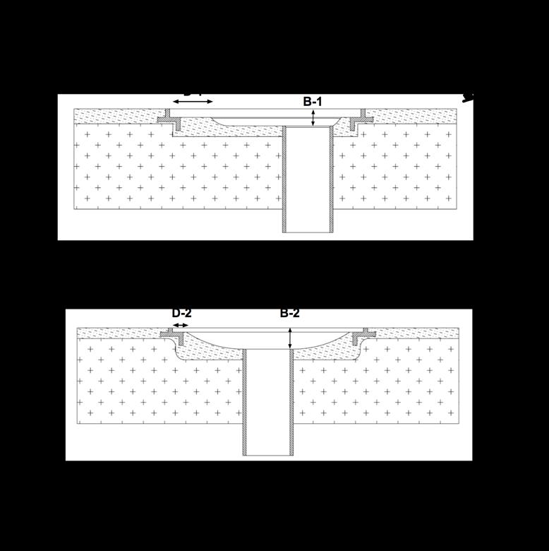

• Zeroing the scale. Paragraph 5.9.6.3 requires that the scale be reset to zero prior to each hair test, including the phrase “when applicable” to allow the use of load cells. Set zero (tare weight) while the hair specimen is submerged and there is no flow-drag caused by water flowing into the SOFA.
• Pull mechanism verification. Pursuant to paragraph 5.9.2, pull speed verification is required using 2 lbm and 10 lbm weights added to the Type 1 (skull) and Type 2 (ponytail) hair specimens.
• Body entrapment test procedure. Section 6.3 and 6.4 replaces the term “immediate” with a 2-second allowance to remove the applied 120 lbf and another 2 seconds to begin mechanical removal of the BBE from the cover/grate.
• Hair preparation. Section 5.9.3 clarifies how the hair is to be prepared prior to testing, including a new requirement for new hair to be conditioned by performing ten tests prior to performing the certification tests. It is critically important to brush/comb the hair between each test.
• Hair test approach. Section 5.9.5 provides new detail for conducting the hair tests, including reducing the hair wave approach time from 60 seconds to 30 seconds. The approach must be uniform and use a continuous sweeping motion as first described in the CPSC document “CPSC Staff Report on Proposed Changes to Entrapment Ratings Tests in APSP-16 2011,” dated April 17, 2014.
• Hair test consecutive runs. Section 5.9.7 provides a flow optimization procedure that is not required when manufacturers choose to specify a lower, passing flow rating, as permitted under Section 1.3.7.
Step 1 – Confirm BBE is neutral buoyant with 0.7 lbf at the test depth, then measure the test flow rate with the BBE > 8 inch above the cover/grate to assure the BBE does not influence the flow measurement.
Step 2 – BBE begins to press against cover/grate as indicated by a force > 0.
Step 3 – When the applied force > 120 lbf, start an applied force timer.
Step 4 – When the applied force = 0 lbf, stop the applied force timer and start a removal force timer. Performance requirement – The applied force timer must be ≤ 2 seconds to be a valid test.
Step 5 – Observe the BBE position and stop the removal force timer when it begins to move up. Alternatively, stop the removal force time when a removal force ≥ 0 lbf is observed. Performance requirement – The BBE must begin to move up from the 0 lbf position within 2 seconds to be a valid test.
• Instructions. Pursuant to Sections 3.3, 3.4 and 9, instructions must now also address cover/grate security, fastener inspection, winterization and repair. The standard does not mandate the level of detail provided.
• Product specifications. To assist users in selecting an appropriate cover/grate for the application, the Standard now requires certain information to be made available prior to users acquiring the physical product. Information includes but is not limited to the SOFA specific flow rating, minimum/ maximum sump dimensions, whether or not the product is authorized for installing on single drain systems, and all compatible pipe sizes. The standard does not mandate where or how the information is to be provided.
• Installation information label. Pursuant to Section 8.4, manufacturers must now include a product information document with the product packaging. It must be suitable for posting near the pump controls. The purpose is to provide SOFA-specific installation information, included cover/grate service life timing, site-specific system flow limits and the installation location. It does not have to be weather resistant. This is separate from the required warning label (see below). ,
• Required tag or label. Pursuant to Section 9.8, manufacturers must attach or affix a warning tag or label to each manufactured cover/grate.
Other new requirements
• Specification of flow path zone. Paragraph 3.5.1.1 requires manufactures to include the Flow Path Zone for each Model SOFA as part of the product specifications. Registered Design Professionals must provide this information in accordance with paragraph 3.9.3.
• Minimum sump depth. This Standard no longer allows sump depths based on 1.5 times the suction pipe diameter. Manufacturers and Registered Design Professionals must now specify minimum sump depth in accordance with Sections 3.5 and 3.9.2.
• Pipe size. Paragraph 3.5.1.1 requires that the manufacturer specify pipe diameter. The hair test must be performed on each specified pipe diameter and orientation.
• Manufactured, unblockable drains. Pursuant to paragraphs 1.3.2.1 and 1.3.7, among other sections, flow ratings on unblockable manufactured SOFAs cannot be determined by calculation. They must be subjected to the test protocols in the Standard. Calculation of flow rating can only be done on field-fabricated units, which must be designed by a Registered Design Professional.
• General Certificate of Conformity (GCC). Federal law requires SOFA manufacturers to certify that products conform to this Standard. The certificate must be based on test data acquired in conformance with Section 1.3.2. The GCC is sufficient evidence of conformity and may be relied upon by all retailers, installers or pool/spa owners. There are no additional listing requirements under the Virginia Graeme Baker Pool and Spa Safety Act (VGBA) or Consumer Product Safety Improvement Act (CPSIA).
This Appendix is not part of the American National Standard ANSI/APSP/ICC-16 2017. It is included for information only.
Notice: The following information is reprinted from the Federal Register: Consumer Product Safety Commission, 16 CFR Part 1450 [Docket No. CPSC-2019-0012] Virginia Graeme Baker Pool and Spa Safety Act (VGBA); Incorporation by Reference of Successor Standard. ACTION: Direct final rule.
Section 1404(b) of the VGBA specifies a standard for drain covers. It states, “each swimming pool or spa drain cover manufactured, distributed, or entered into commerce in the United States shall conform to the entrapment protection standards of [the drain cover performance standard].” Section 1404(a) of the VGBA states that the requirements of section 1404(b) shall be treated as a consumer product safety rule under the CPSA. Thus, the drain cover must be in compliance with the drain cover standard at the time of manufacture of the cover, distribution of the cover, or when the cover is entered into commerce. This indicates that the drain cover standard is a standard for the drain cover, as a discrete product.
Specific Sections of APSP-16 2017 That Exceed Commission Authority. APSP-16 2017 contains many changes that extend beyond the requirements for the drain cover or SOFA itself, and thus, exceed CPSC's authority under section 1404(b) of the VGBA. The voluntary standard can have such provisions. However, the Commission does not have authority to enforce them as mandatory standard provisions. The changes include requirements that can be separated into the following categories:
• Installation of the SOFA;
• Requirements applicable to pools;
• Activities of pool owners;
• Changes to statutory definitions in the VGBA.
The changes specific to each category are detailed in Tables 1 through 4.
Table 1—Sections of APSP-16 2017 That Are Beyond the Authority of CPSC Because They Establish Requirements for the Installation of the SOFA
Section
1.3.3.2 Drain covers can only be installed on SOFAs deemed suitable by the drain cover manufacturer.
3.5.1 Drain covers shall only be installed on sumps in configurations authorized by the drain cover manufacturer's installation instructions, and at a specific flow rating.
3.6.1 SOFA must be installed per the manufacturer's instructions.
3.6.3.2 Compliance with the standard requires selecting and installing a SOFA or combination of SOFAs such that the flow rating of the SOFAs is greater than the maximum system flow of the pool.
3.6.4.2 The flow rating for existing pools with blockable SOFAs is the flow rating of the SOFA, when also installed in conjunction with an additional device or system designed to prevent suction entrapment (“secondary anti-entrapment system”). A single, blockable SOFA installed in existing pools with no secondary anti-entrapment system results in a flow rating of zero.
3.7.2 Blockable SOFAs installed in existing pools must also be installed with a secondary anti-entrapment system.
3.7.3 Covers or grates marked unblockable may be installed in pools with multiple SOFA systems. Covers or grates marked unblockable may also be installed in pools with single SOFA systems when this use is authorized by the cover/grate manufacturer.
9.4.1 Blockable covers may only be installed in multiple-SOFA systems, or in pools that are also equipped with one or more secondary anti-entrapment systems.
The provisions mentioned in Table 1 set forth requirements for how to install the SOFA. The 2011 version of the APSP standard addressed installation by requiring that certain information about installation be provided in labels and instructions. In contrast, the provisions referenced in Table 1 require that the installer or pool owner/operator take certain actions. These are not provisions for the drain cover. A drain cover manufacturer has the ability to provide labels and instructions with the product. A drain cover manufacturer does not control how the product is installed.
Table 2—Sections of APSP-16 2017 That Are Beyond the Authority of CPSC Because They Establish Requirements for Pools
Section No. Summary of topic(s) covered
1.3.3.1 A pool's system suction flow must not exceed the rating of the installed SOFA(s). A pool with SOFA(s) that were not installed per the manufacturer's instructions is not in compliance with the standard.
3.6.3.1 A pool's system flow ratings cannot exceed the SOFA flow rating while the pool is open to bathers.
3.6.4.1 For multiple blockable SOFA systems, the maximum system flow rating for the pool is determined by subtracting the flow rating of the largest SOFA.
3.6.4.3 The system flow rating for pools with unblockable SOFA(s) shall be determined by combining the flow rating of all SOFA(s).
3.7.1 In new pool construction, the use of a single blockable SOFA is not permitted.
The provisions mentioned in Table 2 set forth requirements for pools, not for drain covers. Several of the provisions set requirements for the pool's flow rating. The 2011 version of the APSP standard required markings and instructions regarding operation at an appropriate flow rating. However, the revised standard states requirements for the pool; these are requirements the drain cover manufacturer lacks the ability to fulfill.
Section No. Summary of topic(s) covered
1.1.3 Drain covers must be replaced at the end of their stated service life.
3.6.2 No modifications to SOFAs or the SOFA flow paths are permitted unless they are subsequently re-tested.
The provisions mentioned in Table 3 require pool owners to take certain actions. The 2011 version of the APSP standard required that components of drain covers be marked to state the component's life span. In contrast, the revised standard requires that drain cover components be replaced at the end of their service life. This change makes the requirement apply to the pool owner, not the drain cover manufacturer. Similarly, a requirement prohibiting modifications to installed SOFAs applies to the pool owner, not the drain cover.
Section No. Summary of topic(s) covered
9.4.1 Requires that blockable SOFAs have installation instructions stating that SOFAs shall be installed only in multiple SOFA systems or instructions shall state that the installer shall include one or more of the following devices or systems
9.4.1.1 Provides a definition of safety vacuum relief system (SVRS).
9.4.1.2 Provides a definition of suction-limiting vent system (SVLS).
9.4.1.3 Provides a definition of gravity drainage system.
9.4.1.4 Provides a definition of automatic pump shut-off system.
9.4.1.5 Provides a definition of drain disablement.
9.4.1.6 Provides a definition of other secondary anti-entrapment systems.
The provisions listed in Table 4 set forth what seem to be requirements for instructions. As is stated above, CPSC standards can include requirements for instructions. However, the instructions specified in section 9.4 actually establish requirements for pools and for secondary devices and systems designed to prevent suction entrapment. All of section 9.4 exceeds the Commission's authority under Section 1404(a) of the VGBA because the instructions require secondary systems on all pools. The VGBA only requires secondary systems for public pools. In addition, this section provides definitions of the secondary systems that differ from the statutory definitions in the VGBA.
This page is intentionally left blank.
This page is intentionally left blank.
This page is intentionally left blank.