3 minute read
4 Device Configuration
4.1Device Initialization
It needs to set the user password when logging in for the first time (the username is admin by default). The figures listed in the following chapter are for reference only. There is difference about interface between different devices, please refer to the actual device for more details.
Caution
It fails to use device if the device is not initialized.
In order to make sure the device is safe, please keep admin user password well after initialization and modify it regularly.
It can implement device initialization only when the device IP address (192.168.1.108 by default) and the PC IP address are in the same network segment.
Step 1
Open IE browser, input camera default IP address in the address bar, and then press Enter
Note
The factory default IP address is: 192.168.1.108
The system will display the interface of Device Initialization after it is successfully connected, which is shown in Figure 4-1
Figure 4-1
Step 2
Set the login password of admin; please refer to Table 4-1 for more details about the parameters.
Parameter Note
Password
Confirm Password
The password can be set as 8 to 32 nonblank characters, which can be made up of number, letter and special character (except “'” , “"” , “;” , “:”and“&”), and it has to contain at least two types of characters. Please set the password with high security according to the password intensity prompt.
Email Address In order to reset password, please input email address properly or update in time
Table 4-1
Step 3
Click Save to complete initialization.
4.2Modify IP Address
In order to make the camera get access to network smoothly, please plan IP address reasonably according to the actual network environment.
Step 1
Log in camera WEB interface in the IE browser.
Note
The factory default IP address is: 192.168.1.108.
The default user is admin; the password is set during device initialization.
Step 2
Select “Setup > Network > TCP/IP” and the system will display the interface of “TCP/IP”, which is shown in Figure 4-2

Step 3
Configure relevant info of IP address, click Save
4.3Live Video
Note
Different devices might have different WEB interfaces, the figure in this document is just for reference, please refer to the document WEB Operation Manual in the disk and the actual interface for more details
Step 1
Log in camera WEB interface in the IE browser.
Note
IP address is the one which has been modified.
Default user is admin; the password has been set during device initialization.
Step 2
Click Login and the system will display the WEB main interface, which is shown in Figure 4-3

Note
It will prompt you to install plug-in for the first system login, please save and install plug-in according to prompt. The WEB interface will refresh automatically after plug-in installation is completed, then live video will show up.
4.4Alarm Setup
Note
Some devices do not support alarm function, the chapter cannot be applied.
It has to cut off power first when connecting cables.
Alarm input and output connection description
Step 1
Connect alarm input device to alarm input port of I/O cable.
Step 2
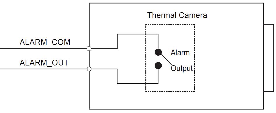
Connect alarm output device to alarm output port of I/O cable, alarm output is relay switch output, the alarm output port can only be connected to NO alarm device.
Step 3
Open WEB interface, select “Setup > Event > Alarm” .

Step 4
Make corresponding settings upon alarm input and output in the alarm setup interface, and then click Save
The interface of alarm setup is shown in Figure 4-4.

Alarm input is corresponding to the alarm input port of device I/O cable. It is to set corresponding NO and NC according to the high and low level signal generated by alarm input device when alarm occurs.
Alarm output is corresponding to the alarm output port of device I/O cable.
Alarm input and output figures
Alarm input: input signal is idle or grounded; the device can collect different states of alarm input port. Input signal is connected to 3.3V or idle, device collects logic “1”; input signal is grounded, the device collects logic “0” .
Alarm output: port ALARM_OUT and ALARM_COM form a switch, which can be used to provide alarm output. Normally the switch is on, the switch will be off when there is alarm output.


