2 minute read
2 Design
2.2 Cables
The length of the cable is about 1.5 m.

Table 2-1 Ports description
No. Port Description
Inputs 36 VDC or 48 VDC.
1 POWER
Refer to the labels attached to the Camera; otherwise the Camera might be damaged.
2 RS485_A (yellow) Controls such devices as external PTZ. RS485_B (orange)
3 VIDEO OUT
BNC port that outputs analog video signals and can be connected to TV monitor to view images.
4 LAN Connects to standard Ethernet cable.
AUDIO OUT Outputs audio signals to such devices as speaker.
5
AUDIO IN Inputs analog audio signals from such devices as sound pick-ups
AUDIO GND Ground port.
6 I/O
7
Inputs and outputs alarm signals. For more details, see Table 2-2. For details on alarm configuration, see "5 Alarm Configuration".
Port Cable port name Description
ALARM_OUT1
ALARM_COM1
Outputs alarm signal to alarm device.
ALARM_OUT1 must be used together with Alarm COM1.
ALARM_OUT2 Outputs alarm signal to alarm device.
I/O port
ALARM_COM2
ALARM_OUT2 must be used together with Alarm COM2.
ALARM_IN1–ALARM_IN7 Receives the on-off signal of external alarm source.
ALARM_GND Grounding terminal
3 Basic Configuration
● Configure network before installation or insert SIM card during installation to access 4G network.
● The figures in the manual are for reference only, and might differ from the actual products. For more details, see Thermal Hybrid Camera_Web Operation Manual.
3.1 Initializing Camera
Initialize the Camera through ConfigTool or by logging in to the web page with default IP after connecting the Camera to the computer
● Use ConfigTool to initialize Cameras in batches.
● Use web page to initialize a single Camera. This section uses web as an example.
● Initialize the Camera for first-time use or after factory resetting.
● To secure the Camera data, keep admin password well after initialization and modify it regularly.
● Make sure that the Camera IP address (192.168.1.108 by default) and the computer IP address are in the same network segment.
Step 1 Open browser, enter the Camera default IP address in the address bar, and then press the Enter key
Step 2 Set the login password of admin.
● The email address is for password reset.
● We recommend entering the email address in case you forget the password and reset the password.
Step 3 Click Save.
3.2 (Optional) Modifying IP Address
Set an IP address fitted to the actual network segment to make the Camera access network.
This section instructs you to configure the network when SIM card is not needed.
Step 1 Log in to the Camera web page.
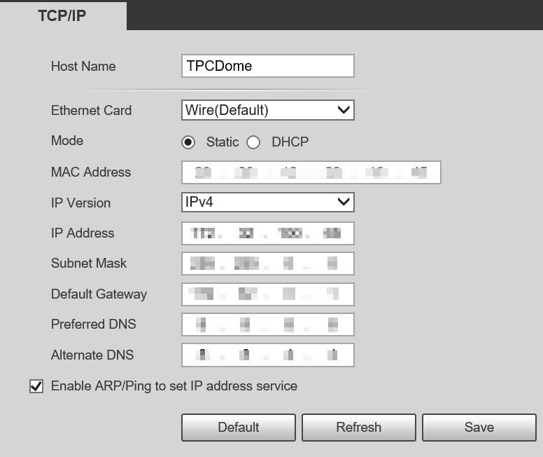
Step 2 Select Setting > Network > TCP/IP.
Step 3 Configure IP related parameters.
3.3 Viewing Live Image
Ensure the Camera can be accessed and live image can be viewed normally after configuring network.

Log in to the Camera web page with the configured IP address. The web main page is displayed.
You will be prompted to install a plug-in for first-time system login. Please download and install the plug-in. The web page will refresh automatically after the plug-in is installed, and then the live video will be displayed.


