General CAUTION
Whenusinganarcwelder,alwaysdisconnect thegroundleadfromthelifttruckbatteryto preventalternatororbatterydamage.Attach theweldinggroundclampasclosetotheweld areaaspossibletopreventweldingcurrent fromdamagingthebearings.
Thediodesandresistorsintheelectricalsystemcanbedamagedifthefollowingcautions arenotfollowed:
•Donotdisconnectthebatterywhentheengineisrunning.Thevoltagesurgecandamagethediodesandresistorsintheelectrical system.
•Donotdisconnectanelectricwirebeforethe engineisstoppedandtheswitchesare"OFF".
•Donotcauseashort-circuitbyconnecting theelectricwirestothewrongterminals. Makesureacorrectidentificationismadeof thewirebeforeitisconnected.
•Makesureabatteryisthecorrectvoltageand polaritybeforeitisconnected.
•Donotcheckforcurrentflowbymakinga sparkbecausetheelectroniccomponentscan bedamaged.
NOTE: Informationonalternatorsmanufactured outsidetheUnitedStatesisintheSRM(Service RepairManual)sectionsforlifttrucksthatusethose alternators.

Thissectionhasadescriptionandtherepairproceduresforthealternatorwithavoltageregulatoras partofthealternator.
Description
NOTE: ForthisSRMsection,thealternatorsarein twogroups,TypeAandTypeB.Thetwotypesare verysimilar,buttheTypeAalternatorshaveasetof threediodes(diodeset)aswellasthediodebridge. TheTypeBalternatorhaszenerdiodesaspartof thediodesinthediodebridge.Thisalternatordoes nothaveadiodeset,butdoeshaveanadditionalfan insidetherearhousing.Thebasicoperationofboth typesisverysimilar.
Thealternatorgeneratesanalternatingcurrent whentheengineisrunning.Thealternatoriseither ON or OFF.Thealternatorgeneratesmaximum currentwhenitis ON andnocurrentwhenitis OFF.Theregulatorswitchesthealternatorbetween ON and OFF togettheaveragecurrentneededto chargethebattery.Alternatoroutputisdirectly changedbyenginespeedandrotorfieldcurrent.The alternatingcurrentischangedtoadirectcurrentby thediodebridgeinsidethealternator.
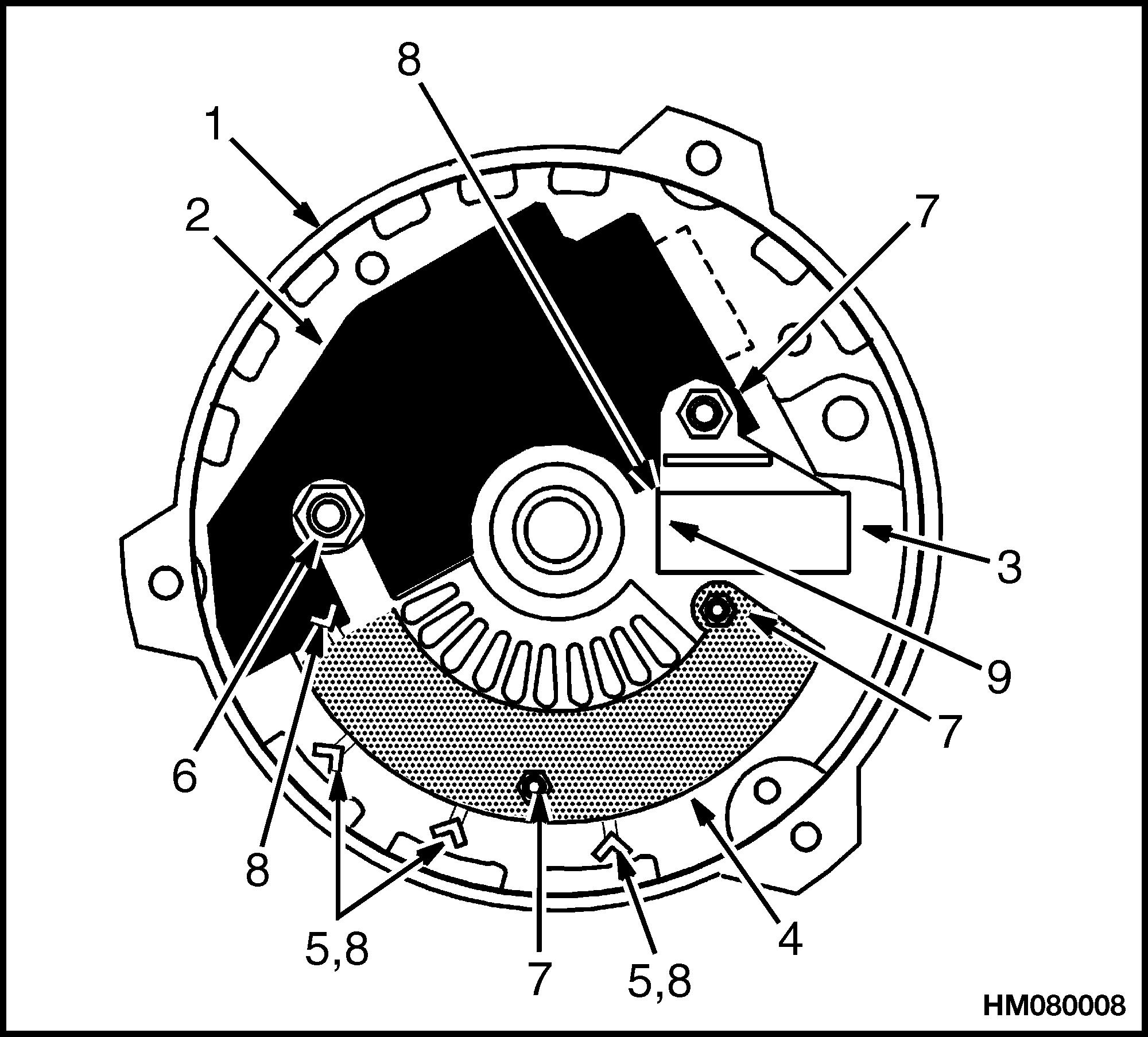
Thealternatorhastheseparts(seeFigure1andFigure2):
Astator
Arotor
Adiodebridge
Adiodeset(TypeAonly)
Twoendhousingsorframehalves
Asolid-statevoltageregulator
NOTE: DELCOTYPEASHOWN.
1.BRUSHASSEMBLY
2.ROLLERBEARING
3.GREASE RESERVOIR
4.LIPSEAL
5.DIODEBRIDGE
6.BALLBEARINGS
7.FELTSEAL
8.REGULATOR

LegendforFigure2
NOTE: LEECE-NEVILLENOTAVAILABLE,SIMILARTOTHOSESHOWN.
A. DELCOTYPEA(SMALLCAPACITYLIFT TRUCKS) B. DELCOTYPEB
C. MOTOROLATYPEA
D. DELCOTYPEA(LARGECAPACITYLIFT TRUCKS)
Thedirectcurrentfromthediodesofthediodebridge flowstotheoutputor"BAT"terminal.Acapacitorbetweenthe"BAT"terminalandtheelectricalground removesanyremainingalternatingcurrentfromthe directcurrent.Thecapacitoralsoprotectsthediodes fromhighvoltages.Thevoltageiscontrolledbythe amountofcurrentflowingthroughthefieldwinding inthealternatorandtherpmoftherotor.Thevoltageregulator,insidethehousing,containsatransistor,diodes,resistors,andcapacitor.Thevoltageregulatorcannotberepaired.
NOTE: Onsomelargecapacitylifttrucks,thealternatorhasanexternalvoltageadjustment.
ALTERNATORTYPEA
RemoveandDisassemble
WARNING
Thevoltageregulatorcontrolsthealternatorto chargethebattery.Thevoltageissetbythemanufacturerandisnotusuallyadjustable.Battery voltagedecreasesasthestartingcircuitandother circuitstakeenergyfromthebattery.Whenthe keyswitchisputinthe" IGN "position,thevoltage regulatorisenergized.Apositivecurrentflowsto thefieldterminal("F"or"1")onTypeAalternators "(L")ontypeB.Thebatterysendsapositivecurrent totheregulatorterminal(TypeA"R"or"2")andthe "BAT"terminal.Theregulatorsensesadecreasein batteryvoltageandincreasesthealternatoroutput tochargethebattery.
AlternatorRepair
Alwaysdisconnectthebatterygroundcablebeforemakingrepairstopreventpossibledamageandinjury.Installatagonthebatteryterminalsothatnooneconnectsthecableonthe terminal.
NOTE: UseTroubleshootingandGeneralCheckand Adjustment,LowOutputCheck(TypeAorTypeB), HighOutputCheck(TypeAorTypeB),BrushesCircuitCheck,DiodesCheck,DiodeBridgeCheck,Rotor FieldWindingCheck,StatorWindingsCheck,and VoltageRegulatorCheckproceduresofthisSRMbeforestartinganyrepairprocedures.Makesurethat repairorreplacementofthatpartisnecessarybefore removal,disassembly,orreplacementofthepart.
NOTE: Therearesomechecksofthealternatorthat aredonewiththealternatorontheengine.See GeneralCheckandAdjustment,LowOutputCheck (TypeAorTypeB),HighOutputCheck(TypeA orTypeB),BrushesCircuitCheck,DiodesCheck, DiodeBridgeCheck,RotorFieldWindingCheck, StatorWindingsCheck,andVoltageRegulator CheckproceduresofthisSRMbeforestartingany removalorrepairprocedures.
NOTE: ManypartsoftheLeece-Nevillealternator canbereplacedwithoutdisassemblingthealternator.SeeFigure5.Thealternatormustbedisassembledtoreplaceonlythediodebridge,filtercapacitor, rotor,stator,orbearings.
1. Disconnectthebatterygroundcable.SeeFigure3,Figure4,andFigure5.Installlabelsand disconnectthewiresatthealternator.Loosen thealternatormountcapscrewsandremovethe drivebelt.Removethecapscrewsthatholdthe alternatortotheengine.
2. OnLeece-Nevillealternators,removethe brushes,voltageregulator,ordiodeset.Install labelsonallwiresforcorrectconnectionduring installation.
3. Putamarkoneachhousingandonthestatorfor correctalignmentduringassembly.Removethe boltsthatholdthehousingstogether.Separate thehousingsandstator.
4. Puttherotorinavisethathassoftjaws.Donot tightenthevisetocauserotordistortion.Usea socketwrenchtoremovethepulleynut.Remove
thepulley,fan,collar,spacer,shield,orother partsbetweenthefanandhousing.Removethe fronthousingfromtherotor.
5. Removeanynutsorscrewsthatfastenpartsinsidetotherearhousing.Then,removethestatorassemblyfromtherearhousingsothatthe otherpartscanberemoved.Removethescrews forthecapacitor,diodebridge,diodeset,brushes, andotherpartsasnecessary.Ifthestatorwill beremovedfromthediodebridge,makesurethe wireshavetagsforcorrectconnectionduringassembly.
6. Markthestatortoshowthepositionofthe brushesandconnectorordiodebridgeassembly. Usepliersasaheatsinktokeepheatfromthe diodes.Useasolderingirontoremovethestator leadsfromthediodeassembly.
7. Removethebearingsfromthehousingsonlyif theywillbereplaced.
Clean
CAUTION
Neverusesolventonthepartsofthealternator.
NOTE: Ifnecessary,usefineabrasiveclothtopolish thesliprings.Theabrasiveclothmustbenumber
500to600.Removealldust.Turntherotorwhile polishingthesliprings.
Usecompressedairtoremovedirtfromthealternator.Cleanthebrushesandslipringswithaclean, drycloth.
Assemble
1. ForDelco(TypeA)alternators,installanew bearing(s)inthehousingasfollows(seeFigure3,Figure4,andFigure5):
a. Installanewplugandsealintherearhousing.Pushthebearingfromtheoutsideofthe housinguntilthetopofthebearingiseven withtheoutsideofthehousing.Holdthe

housingwiththecollarontheinsideofthe housing.Keepthelipofthesealawayfrom thebearing.Lubricatethebearingareawith Delco-Remygrease,partnumber1948791.
b. Installanewbearinginthefronthousing. Fillonequarterofthegreasereservoirwith Delco-Remygrease,partnumber1948791, orequivalent.Movethegreasesothatit touchesthebearingwhentheretainerplate isinstalled.
c. Addthesametypeofgreasetofillthearea betweentheretainerplateandthebearing. Installthespacer,gasket,andretainerplate onthebearing.Fastentheretainerplate inpositionwiththethreescrewsandlock washers.
2. ForMotorolaandLeece-Nevillealternators,use apresstoinstalltherearbearingontherotor. Installthebearingandbearingretainerinthe fronthousing.Ifused,installthespaceronthe bearing.
CAUTION
Holdtherotorinavisethathassoftjaws.Do nottightenthevisemorethannecessary.
3. Installthefronthousingontherotor.Ifused,installthespacerorshield,shaftkey,andwasher. Installthefan,pulley,lockwasher,andnut. Tightenthenutto54to81N•m(40to60lbfft).
CAUTION
Besuretoinstalltheinsulators.Makesurethe heatsinkdoesnottouchthehousing.
4. Installthediodebridgeandheatsinkinthereverseorderofdisassembly.Makesuretheinsulatorsandwashersareinthecorrectpositions. Installthecapacitor.
5. OnDelcoalternators,installpartsasfollows:
a. Installthebrushandholder,voltageregulator,anddiodesfromtheinsideofthealternator.Makesuretheinsulatorsleevesareon thescrewsforthebrushholder.Installthe capacitor.
b. Installthestatorintherearhousing.Connectthethreewiresfromthestatortothe diodebridgeandfastenatthestuds.Connectthewiresfromthediodestothestuds
onthediodebridge.Installandtightenthe threelockwashersandnuts.
c. Installthebrushesinthebrushholders. Toholdthebrushesinposition,putapin throughtheholeinthebrushholders.Apply athinlayerofoiltothelipofthesealforthe bearing.
6. OnMotorolaalternators,installpartsasfollows:
a. Installthediodebridgeonthestator.Use plierstokeeptheheatfromthesolderingiron awayfromthediodes.
b. Installthecapacitor,diodeset,andterminalonthediodebridge.Alignthemarks madeduringremovalandinstallthestator andbridgeassemblyintherearhousing.
7. Alignthemarksmadeduringdisassembly.Carefullyinstallthestatorandtherearhousingover therotor.Donotdamagethesealwhilesliding thehousingovertherotorshaft.Installthefront housing.
8. Installthefourscrewstoholdthealternatortogether.OnDelcoalternators,removepintoreleasethebrushes.
9. OnMotorolaalternators,installthebrushholder andbrushes.Makesurethewasherisonthe right-handscrew.Installthevoltageregulator andtightenthescrews.
10. OnLeece-Nevillealternators,installthe brushes,voltageregulator,ordiodesetin thereverseorderofremoval.
Install
1. Installthealternatorinthebracketontheengineandadjustthetensionofthebelt.
2. Connectallwiresandtheconnectoraccordingto thelabelsmadeduringremoval.Alsoseethe schematicdiagramforyouralternatorinFigure2.Makesureallwiresareconnectedcorrectlyandallfastenersaretight.SeeFigure3.
3. Checktheindicatorlightortheammetertocheck theoperationofthealternator.Theindicator lightforTypeAalternatorswillonlybeONifthe batteryisdischarged.

LegendforFigure4

ALTERNATORTYPEB
RemoveandDisassemble
WARNING
Alwaysdisconnectthebatterygroundcablebeforemakingrepairstopreventpossibledamageandinjury.Installatagonthebatteryterminalsothatnooneconnectsthecableonthe terminal.
NOTE: UsetheTroubleshootingandGeneralCheck andAdjustment,LowOutputCheck(TypeAorType B),HighOutputCheck(TypeAorTypeB),Brushes CircuitCheck,DiodesCheck,DiodeBridgeCheck, RotorFieldWindingCheck,StatorWindingsCheck, andVoltageRegulatorCheckproceduresofthisSRM beforestartinganyrepairprocedures.Makesure thatrepairorreplacementofthatpartisnecessary beforeremoval,disassembly,orreplacementofthe part.
NOTE: Therearesomechecksofthealternatorthat aredonewiththealternatorontheengine.See GeneralCheckandAdjustment,LowOutputCheck (TypeAorTypeB),HighOutputCheck(TypeA orTypeB),BrushesCircuitCheck,DiodesCheck, DiodeBridgeCheck,RotorFieldWindingCheck, StatorWindingsCheck,andVoltageRegulator CheckproceduresofthisSRMbeforestartingany removalorrepairprocedures.
1. Disconnectthebatterygroundcable.SeeFigure6,Figure7,andFigure8.Installlabelsand disconnectthewiresatthealternator.Disconnectthewireconnector.Loosenthealternator mountcapscrewsandremovethedrivebelt.Removethecapscrewsthatholdthealternatorto theengine.
2. Putamarkoneachhousingandonthestatorfor correctalignmentduringassembly.Removethe boltsthatholdthehousingstogether.Separate thehousingsandstator.
3. Puttherotorinavisethathassoftjaws.Donot tightenthevisetocauserotordistortion.Usea socketwrenchtoremovethepulleynut.Remove thepulley,collar,fan,outsidecollar,fronthousing,andinsidecollarfromtherotor.
NOTE: Thecovermustbereplacedifthepartswill beremovedfromthestator.Ifnecessary,removethe statorasdescribedinStep4andStep5.
4. Useapunchtoremovetherivetsorpinsthat fastenthecover.Removethecoverforaccessto thestatorleads.Discardthecover.SeeFigure7.
5. Cutthestatorleadsasclosetotheconnectorsas possible.Installlabelsontheleadsforcorrect connectionduringassemblyandremovethestatorfromtherearhousing.
6. Useapunchtoremovethethreebafflepinsand removethebaffle.SeeFigure7.
NOTE: CarefullymakeanoteofthesequenceofremovalofpartsinStep7andStep8forcorrectinstallation.Alsomakeanoteofalltypesofconnections (crimp,soldered,orwelded)aswellasallmechanical fasteners.
7. Removethethreemountscrewsand"BAT"terminalnut.SeeFigure8.Liftthebrushholder, voltageregulator,anddiodebridgefromthe housing.
8. Openthecrimpsoruseasolderingironand disconnecttheconnectorstoseparatethebrush holder,voltageregulator,anddiodebridge.
9. Ifthebearingwillbereplacedintherearhousing,removethebearingandretainerring.
CAUTION
Neverusesolventonthepartsofthealternator.
NOTE: Ifnecessary,usefineabrasiveclothtopolish thesliprings.Theabrasiveclothmustbenumber 500to600.Removealldust.Turntherotorwhile polishingthesliprings.
Usecompressedairtoremovedirtfromthealternator.Cleanthebrushesandslipringswithaclean, drycloth.
Thank you very much foryourreading.Please Click Here Then Get MoreInformation.
NOTE: If there is no response to click on the link above, please download the PDF document first and then clickonit.
Assemble
1. Ifthebearingwasremovedfromtherearhousing,installanewretainerring.SeeFigure6.
CAUTION
Thebearingisnotcompletelyinstalleduntil Step11iscomplete.
2. Installanewbearingbypushingonthenew bearingouterraceuntilthebearinghitsthe bottomintherearhousing.
3. Assemblethevoltageregulator,diodebridge,and brushholderonaflatsurface.Putcrimpsinthe connectorsorsoldertheconnectorstofastenand connectthepartsasoriginallyassembled.Usea pintoholdthebrushesinthebrushholder.

4. Putathincoatingofsilicongrease(Delcopart number1974984)ontheinsideoftherearhousingunderthediodebridge.
5. Installthebridge,regulator,andbrushholder assemblyintherearhousingandinstallthe screwsasremovedduringdisassembly.
6. Installthebaffleanduseapunchtofastenthe pins.
7. Alignthemarksmadeduringdisassemblyand installthestatorintherearhousing.Usepliers ontheconnectorsofthediodebridgetokeepheat fromthediodes.Useasolderingirontoconnect thestatorleadstotheconnectors.
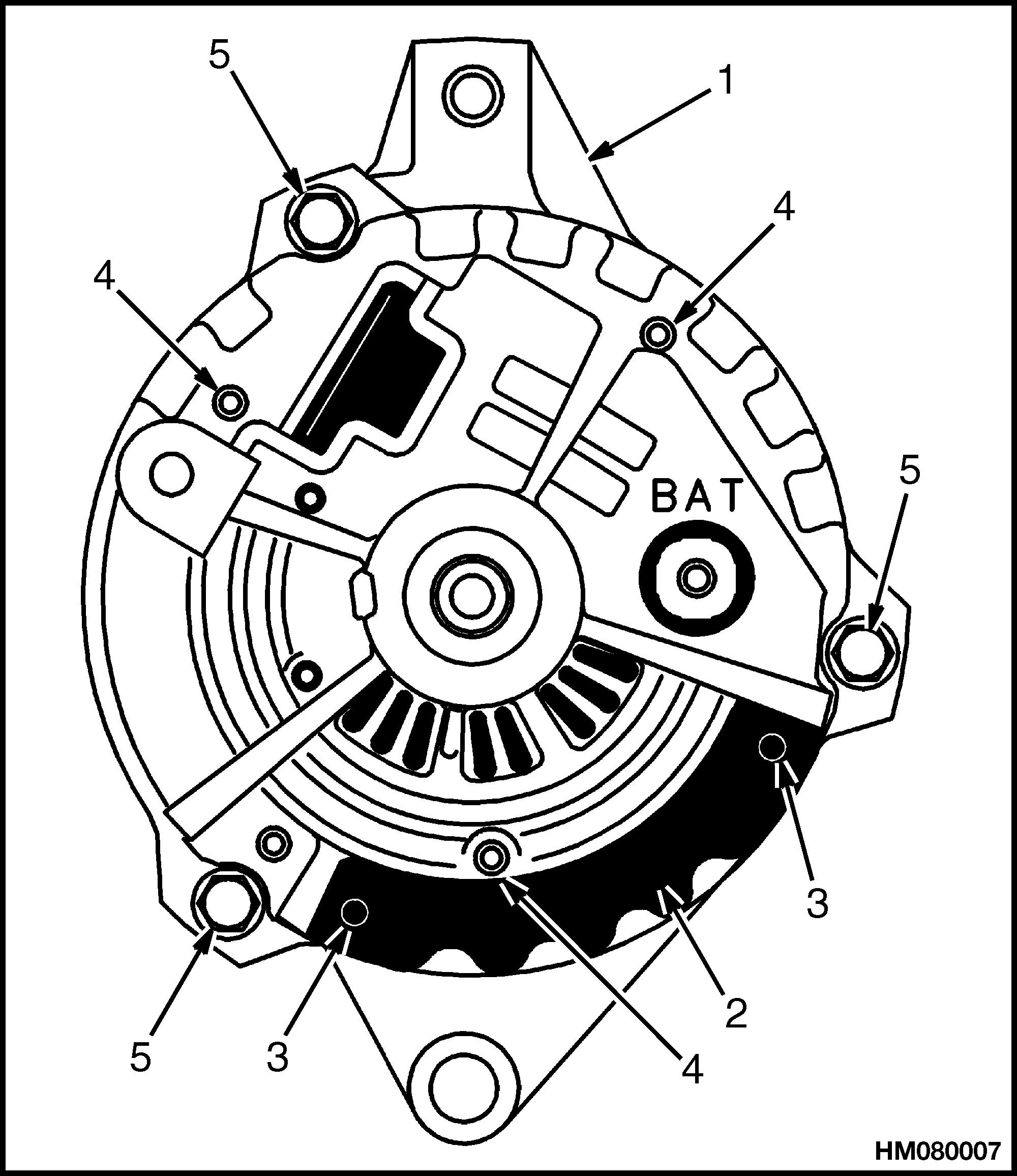
NOTE: TYPEBONLY.
1.REARHOUSING
2.COVER
3.COVERRIVETS ORPINS
4.BAFFLEPINS
5.BOLTSTOFASTEN HOUSINGS TOGETHER
8. Installanewcoverusingrivetsorpinstofasten
9. Ifnecessary,installthebearinginthefronthousing.Puttherotorinavisewithsoftjawsandinstalltheinnercollar,fronthousing,outercollar, fan,collarpulley,andnutontherotor.Tighten thenutto54to108N •m(40to80lbfft).
10. Alignthefrontandrearhousingsusingthe marksmadeduringdisassembly.Pushonboth theinnerandouterracesoftherearbearing topushthetwohousingsandstatortogether. Installthethreeboltsthatfastenthealternator together.
11. Pushonboththeinnerandouterraceoftherear bearingsothattheouterraceis1.9to2.2mm
(0.075to0.087in.)belowthesurfaceoftherear housing.
NOTE: TYPEBONLY.
1.REARHOUSING
2.VOLTAGE REGULATOR
3.BRUSHHOLDER
4.DIODEBRIDGE
5.TERMINALSFOR STATORLEADS
Install
6.NUTON"BAT" TERMINAL
7.MOUNTSCREWS
8.SOLDERED ORWELDED CONNECTOR
9.BRUSHPIN
1. Installthealternatorinthebracketontheengineandadjustthetensionofthebelt.
2. Connectallwiresandtheconnectoraccordingto thelabelsmadeduringremoval.Alsoseethe schematicdiagramforyouralternatorinFigure2.Makesureallwiresareconnectedcorrectlyandallfastenersaretight.SeeFigure7.
3. Checktheindicatorlightortheammetertocheck theoperationofthealternator.Theindicator lightcana lso beONifthealternatoroutputis toohi gh onTypeBalternators.


GeneralCheckandAdjustment
Therearenoadjustmentsforthealternatoror mostregulators.OneDelcoalternatorandthe Leece-Nevillealternatorhasavoltageadjustment. Alwayscheckthegeneralconditionofthecomplete systembeforedoingacompletecheckoneachpart. Checkthegeneralconditionofthefollowingparts: (1)battery,(2)batterycablesandconnections,and(3) alternatorandregulatorwiresandconnectors.Also checktheconditionandtensionofthefanbeltforthe alternator.
CAUTION
NEVERoperatetheengineifthealternator output"BAT"terminalisnotconnectedtothe battery.
Donotshort-circuitorconnectjumperwiresto anyofthealternatorterminalsunlesstoldtoby theprocedures.
Makesurepolarityiscorrectbeforeconnectingabatterychargeroranotherbattery.
Removethebatterycablesandcleantheterminals andcableconnectors.Inspecttheinsulationonthe wires.Makesureallthefastenersandconnections arecleanandtight.Ifnecessary,useawaterand sodasolutiontocleanthetopofthebattery.DoNOT removethecellcapsorpermitthewaterandsoda solutiontogetinthebattery.
WARNING
PutthetransmissioninNEUTRAL.Applythe parkingbrake.
CAUTION
Donotchangethepolarityofthecircuits.Do notconnectanywiresinthecircuits,exceptas describedintheseinstructions.Neverconnect thewirefromtheterminalmarked"BAT"toan opencircuit.
Whenconnectingachargeroranotherbattery,connectthepositiveterminalstothepositiveterminal ofthebattery.Thenconnectthenegativeterminal toacleanmetalpartoftheengine.Disconnectthe chargerorotherbatteryinthereverseorder.Problemsinthechargingcircuitareindicatedbyoneor moreofthefollowing:
• Thestartermotorturnsslowly.Thebatteryvoltage islowbecauseoflowalternatoroutputorabad battery.
• Thespecificgravityreadingsarelow.Batteryis notfullychargedorisdamaged.
• Thebatteryusesmorethan30ml(1oz)ofwater percellpermonth.Thealternatoroutputistoo high.
Thetwoproblemsofthechargingcircuitarelow outputandhighoutput.Lowoutputcausesalow batteryanddifficultstarting.Ahighoutputcauses heatingofthebatteryandevaporationofwaterfrom theelectrolyte.Thefollowingtwocheckswillfind outifthealternator,regulator,orwiringhasthe chargingfault.Thetwocheckswillalsofindoutif thechargingsystemhasacorrectoutput.Dothe followingtwochecksbeforeremoval,disassembly,or replacementofalternatororregulator.
NOTE: Informationonalternatorsmanufactured outsidetheUnitedStatesisintheSRM(service repairmanual)sectionsforlifttrucksthatusethose alternators.
LowOutputCheck(TypeAorTypeB)
CAUTION
Donotconnectthewirefromthe"BAT"terminaltotheelectricalground.
NOTE: Makesurethewirefromthevoltmetermakes contactwitheachterminalonthealternator.
1. Connectavoltmeterbetweenthe"BAT"terminal andtheelectricalground.Turnthekeyswitchto the"ON"positionandcheckthereading.
2. Connectavoltmetertothefieldterminaland theregulatorterminal.Followtheprocedurein Step1andcheckthereadings.
3. Iftherearenoreadingsonthevoltmeterduring Step1andStep2,checkforanopencircuitbetweeneachterminalandthebattery.
4. Iftherearereadingsonthevoltmeterduring Step1andStep2,disconnectthecableforthe electricalgroundonthebattery.
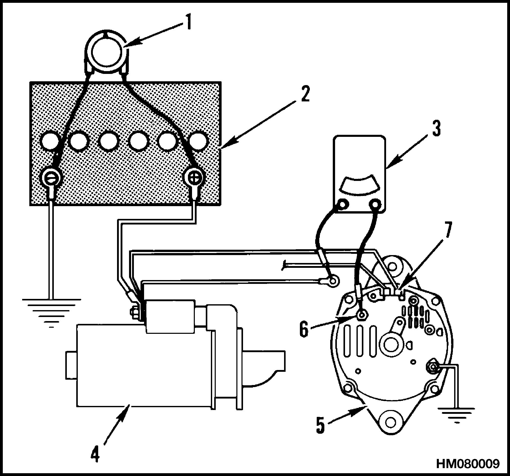
5. MakeconnectionstotheTypeAalternatoras showninFigure9.MakeconnectionstotheType BalternatorasshowninFigure10.
6. Connectthecablefortheelectricalgroundonthe battery.
7. Connectacarbonpileacrosstheterminalsofthe battery.
8. Runtheengineat2000to2500rpm.Adjustthe carbonpileuntilthemaximumchargingrateis reached.
9. Readthevalueofthemaximumchargingrate shownonthealternatorhousingorinthesection CapacitiesandSpecifications foryour lifttruck.Readtheammeter.Thereadingon theammetermustbewithin10%ofthemaximumvalue.
a. Thevoltagesettingcanbeincreasedby changingthepositionoftheadjustment plug."LO"isthelowestvoltagesetting."2" ismediumlowand"3"isthemediumsetting. Thevoltagesettingishighestwhen"HI"is alignedwiththearrowonthealternator. Changethesettingasnecessary.
NOTE: TYPEAONLY.
1.CARBONPILE
2.BATTERY
3.AMMETER
4.STARTER
5.ALTERNATOR 6."BAT"TERMINAL 7.FIELDTERMINAL
Figure9.AlternatorOutputCheck
10. Iftheammeterreadingiswithin10%,thealternatorisingoodcondition.Checkthestarteror wiresforproblems.Somealternatorsonlarger lifttruckshaveavoltageadjustment.SeeFigure12.Foralternatorswiththevoltageadjustment,doStepatosetthevoltage:
NOTE: TYPEBONLY.
1.BATTERY
2.CARBONPILE
3.VOLTMETER
4.RESISTOR(35 OHM5WATTTO 500OHM1/2WATT)
5.AMMETER
6.ALTERNATOR
7."BAT"TERMINAL
8.CONNECTTO"L" TERMINAL
Figure10.AlternatorOutputCheck


11. OnTypeADelcoalternators,dothefollowing checks:
CAUTION
Donotpushthescrewdriverintotheholefor morethan25mm(1in.) .
a. Iftheoutputshownis notwithin10%,puta screwdriverintothe holeshowninFigure11.
b. Runtheengineat2000to2500rpm.Adjust thecarbonpileuntilthemaximumcharging rateisreached.
c. Iftheoutputiswithin10%,checkthefield winding.Ifthefieldwindingisingoodcondition,replacethevoltageregulator.
d. Iftheoutputisnotwithin10%,checkthe wirestothebrushes,diodes,diodebridge, fieldwinding,andstator.
e. Removethescrewdriver,ammeter,andvariableresistor.
NOTE: DELCOTYPEASHOWN.
1.HOLE 2.MAKESURESCREWDRIVERTOUCHES HOUSINGANDMETALTAG.

Figure11.ElectricalGroundonFieldWinding
HighOutputCheck(TypeAorTypeB)
1. Connectavoltmeterfromtheregulatorterminal totheelectricalground.Checkthereadingon thevoltmeter.SeeFigure9orFigure10.
2. Iftherearenoreadings,checkforanopencircuit betweentheregulatorterminalandthebattery.
3. Ifthereisareading,connectavoltmeterbetween the"BAT"terminalandtheelectricalground.
4. Increasetheenginespeeduntilthemaximum voltagereadingisreached.
5. Ifthevoltageshownismorethan15.5voltson a12-voltsystemor31voltsona24-voltsystem, disassemblethealternatoranddotheremainder ofthechecks.Foralternatorswiththevoltage adjustment,dothefollowing:
a. Delcoalternator.Thevoltagesettingcanbe increasedordecreasedbychangingthepositionoftheadjustmentplug.SeeFigure12. "LO"isthelowestvoltagesetting."2"is mediumlowand"3"isthemediumsetting. Thevoltagesettingishighestwhen"HI"is alignedwiththearrowonthealternator.Do notchangethesettingwhenengineisoperating.Changethesettingasnecessary.
b. Leece-Nevillealternator.Removethescrew inthecover.SeeFigure12.Starttheengine. Connectavoltmeteracrossthebatteryterminalsanduseascrewdrivertoadjustthe voltage.

