
General
Thissectionhasthedescriptionandrepairproceduresforthedifferential.ThereareSpecificationsanda Troubleshootingtableattheendofthissection.
Description
Thisdifferentialisfastenedtotheaxlehousingofthe lifttruck.Thedifferentialgivesasingle-speedreductionforanincreaseintorquetothedrivewheels. Thereisahousing,aringandpiniongearset,and thedifferentialassembly.Theringgeartransfers
powerfromthepinionthroughthedifferentialassemblytotheaxles.Thedifferentialassemblypermitsthedrivewheelstorotateatdifferentspeeds duringaturn.
DifferentialRepair REMOVE
NOTE: Therepairprocedurescoverallunitsunless otherwiseindicated.
NOTE: Thedifferentialassemblycannormallybe removedwithoutremovingthedriveaxle.Onsome trucks,includingtheH7.00-12.50H(H150-275H), thedriveaxlemustberemovedtoremovethedifferentialassembly.
1. Disconnectthedriveshaftatthedifferential.If aspeedreducerorgearboxisinstalled,remove thespeedreducerorgearbox.
2. Someunitshaveadrumordiscbrakeattachedto theoutputyoke.Besuretodisconnectanybrake linkageorbrakelines.Seethebrakesectionfor yourunit.
3. Removetheaxleshaftsfromtheaxlehousing. Seethedriveaxlesectionforyourunit.On STRADDLETRUCKS,disconnectthedrive axleuniversaljointsatthedifferentialyokes. Removethecapscrewsthatfastenthebearing retainerstothedifferentialhousing.Pullthe yoke,stubshaft,andbearingretainerfromthe housing.
DISASSEMBLE
1. Usealiftingdeviceasasupportforthedifferential.Removethehousingcapscrewsandremove thedifferentialfromtheaxlehousing.
2. Iftheunithasadrumordiscbrakeattached totheoutputyoke,removeit.Seethebrakes sectionforyourunit.
3. Iftheringandpiniongearswillbeusedagain, checktheclearancebetweenthegearsandmake arecordofthevalue.SeeFigure5.
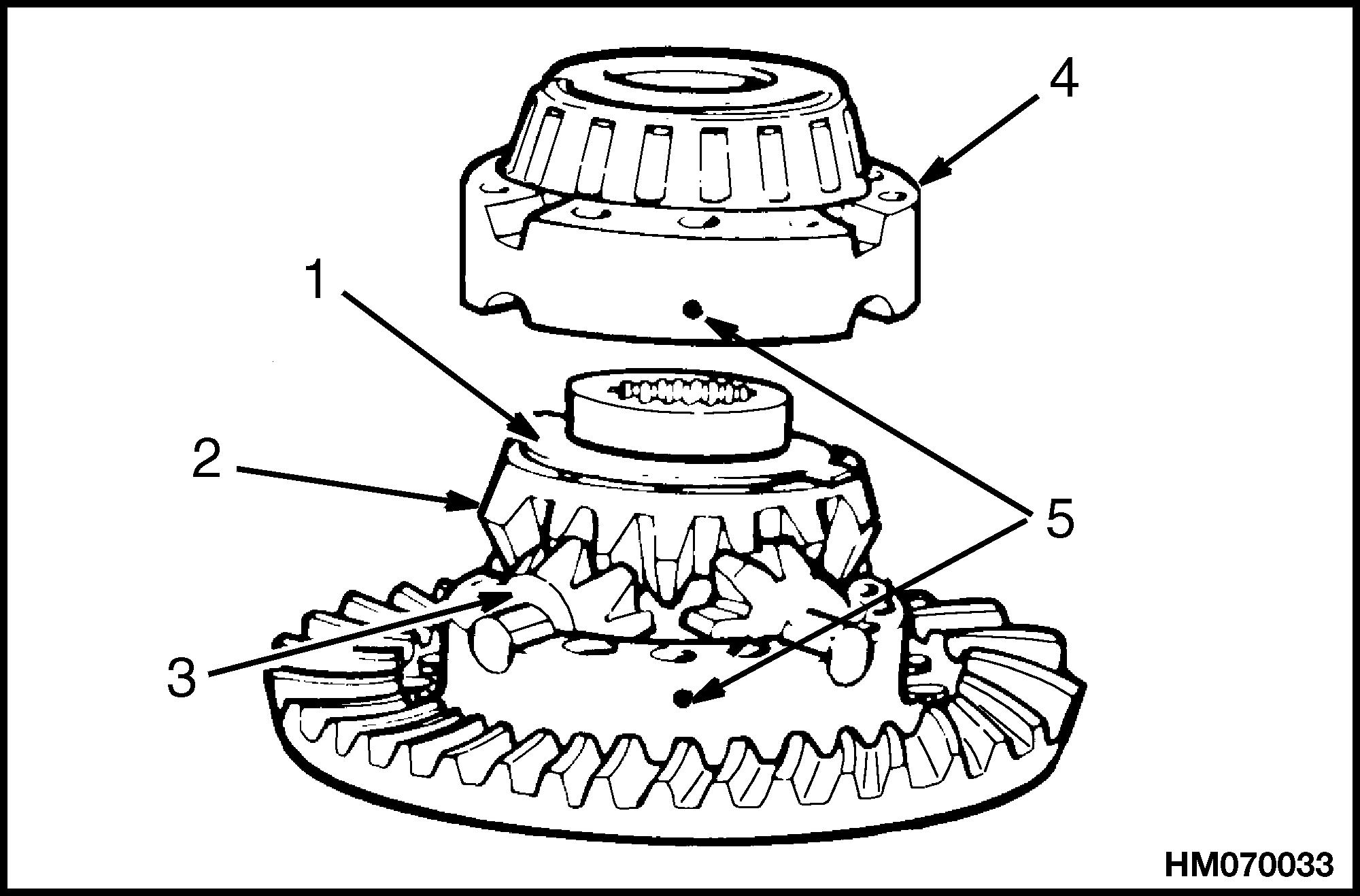
4. Acompletedisassemblyisnotnormallynecessary.Disassemblethedifferentialtomakenecessaryrepairs.SeeFigure1.Putmarksonone bearingcapandthecasehalfsothatitcanbeinstalledinthesameplace.Putmarksoneachhalf ofthedifferentialcasesothattheycanbeassembledinthesameway.Keeptheshimsetforthe pinioncarrierassembly.
CAUTION
Neveruseahammerandchiseltoremovethe rivets.Damagetotheholescanoccur.
5. Ifitisnecessary,removetheringgearfrom thecase.Makesuretherivetholesinthecase arenotdamaged.Useacenterpunchanddrill smallerthantherivetstoremovetherivets. Keeptheoldringgearandpinionset.
ASSEMBLE
Pinion,Bearings,andPinionCarrier, Assemble
1. Putdifferentialoilonthebearingsandcups.Installthecupsinthepinioncarrier.SeeFigure1.
2. Installtheinnerbearingandpilotbearing againstthepinionshoulders.Useasleeveand presstopushagainsttheinnerbearingrace.
*SOMEAXLESDONOTHAVETHEPARTSDESCRIBED

CAUTION
Ifanewpinionisinstalled,anewringgear mustalsobeinstalled.Thepinionandring gearareaset(seeFigure4)andMUSTbeinstalledtogether.
3. Installthepilotbearingwasherandsnapring. Putthepinionassemblyinthepinioncarrier.Installthespacersonthepinion.
NOTE: Duringassemblyatthefactory,onespaceris used.Twothinnerspacersareusedifthepinionor bearingsarereplaced.Thesespacersareselectedfor correctbearingpreload.
NOTE: Somepilotbearingsarefastenedtothepinionwithasnapring,andsomearefastenedwitha punch.Otherscanhaveatwo-piecebearing.
4. Useapresstoinstalltheouterbearingagainst thespacer.Rotatethecarriertomakesurethe bearingsareinstalledcorrectly.Usethepress toapplythecorrectpreload.SeeSpecifications, RivetInstallationPressure.Checkthebearing preloadasdescribedinPinionBearings,Adjust Preloadofthissection.
PinionBearings,AdjustPreload
1. Wrapacordseveraltimesaroundthepinioncarrier.FastenaNewtonorpoundscaletothecord. SeeFigure2.Pullthescaletounwindthecord. Checkthereadingonthescaleasthecordunwindssmoothly.DoNOTusethereadingasthe cordjustbeginstounwind.Thescalereading mustindicate2.2to7.0kg(5to15lb).
Apinioncarrierthathasa76.2mm(3in.)radiusanda2.2kg(5lb)scalereadingisequalto 1.70N•m(15lbfin).Selectaspacersetforthe correctpreload.Athinnersetwillincreasethe preload.
CAUTION
OnH7.00-12.50H(H150-275H)trucks,doNOT usethewasherthatisonthenewpinion.Use thethickerspacer(HysterPN125277).The threadscanbedamagedorthenutcanloosen ifthewasherisused.
2. Ifapresscannotbeusedforpreload,installall thepartsthatareheldbythepinionnut.Tighten thepinionnuttothecorrecttorqueshowninTable1.CheckthepreloadasdescribedinStep1.
1.PRESS 2.SLEEVE
3.PINIONBEARING
Figure2.BearingPreloadCheck PinionCarrierShimSet,AdjustThickness (DepthofPinion)

NOTE: Usethisprocedureifanewringgearandpinionsetisinstalled,orifthedepthofthepinionhas tobeadjusted.
1. Afterthepreloadiscorrectlyadjustedusingthe spacerset,adjustthepinion.Thepinionisadjustedusingshimsonthepinioncarrierassembly.Ifthesameringgearandpinionareused, usetheoldshimset.SeeFigure3.Ifanewring gearandpinionareused,adjustthepinionasdescribed.
CAUTION
Alwaysuseaminimumofthreeshimsforthe shimset.Usethethinnestshimsontheoutside ofthesetforabetterseal.
2. Thecorrectshimsetthicknesscanbefoundby usingtheoldandnewparts.Usetheoldshimset thicknessandthenumbersontheoldandnew pinionandringgearsets.Forthelocationand identificationofthenumbers,seeFigure4.
NOTE: Alwayscheckthegearsetforthecorrect markstomakesurethegearsareamatchedset.
3. Thelocationofthepinionandringgearmarks areshowninFigure4.Thedescriptionofthe marksisasfollows:
PARTNUMBER.Thepartnumbersarethe partnumberofthemanufacturer.Thepartnumberfortheringgearisalwaysanevennumber. Thepartnumberforthepinionisthenextodd number.Checktomakesurethepinionandring gearareinasequence.Examplesofgearsetpart
numbers:ringgear,36786;drivepinion,36787. Ifagearsetnumberhasaletterthatfollowsthe number,thelettersmustbethesameforboththe ringgearandpinion.


GEARTEETHNUMBER.Thegearteeth numbersarethenumbersoftheteethonthe pinionandringgear.Thenumberofpinionteeth isthefirstnumber.Anexampleofthisnumber is5-37.Intheexample,thedrivepinionhas5 teethandtheringgearhas37teeth.
GEARSETNUMBER.Thegearsetnumber isaletterandnumber.Makesuretheletterand numberarethesameonthedrivepinionandring gear.AnexampleofagearsetnumberisM29.
PINIONCONENUMBER.Thepinioncone number,isthevariationfromthedesigncenter.Thedesigncenteristheexactdesigndistancefromtheendofthepinionconetothe ringgearcenterline.SeeFigure5.
1.PINIONCONENUMBER(VARIATION)
Figure5.PinionConeNumberLocation

NOTE: Thepinionconenumberisnotusedwhenthe gearsetnumberisbeingchecked.Thepinioncone numberisusedwhenyouadjustthedepthofthepinioninthecarrier.
Example:PC+3,PC 3,+3,or 3equals.003inch (variation).PC+.03,PC .03,+.03,or .03equals .03mm(variation).
Findthecorrectthicknessoftheshimsetasfollows:
4. Useamicrometertomeasurethetotalthickness oftheoldshimsetthatwasremovedfromunder
thepinioncarrier.Makeanoteofthemeasurementforlateruse.
5. Checkthepinionconenumberfortheoldpinion. SeeFigure5.Ifthisnumberisaplus(+)value, subtractthevaluefromthevalueinStep4.If thepinionconenumberisaminus( )value,add thenumbertothevalueinStep4.Thenumber shownisin0.00Xinch(+2=+0.002inch).The resultisthestandardthicknessforashimset.
NOTE: ThevaluecalculatedinStep5isthethickness ofthestandardshimset,withoutavariation.
6. Checkthepinionconenumberforthenewpinion.Addorsubtractthisnumbertothestandard thicknessvalueofStep5.Addthenumberifthe valueisaplus(+)value.Subtractthenumberif thevalueisaminus( )value.Theresultisthe correctthicknessforthenewshimset.Seethe examples.
NOTE: ThevaluecalculatedinStep6isthethicknessofthenewshimsetthatwillbeinstalled.See theexamplesshowninSpecifications,PinionAdjustment.
CAUTION
Alwaysuseaminimumofthreeshimsforthe shimset.Usethethinnestshimsontheoutside ofthesetforabetterseal.
7. Installthepinioncarrierassemblyusingthecorrectshimset.SeeFigure6.TightenthecapscrewstothecorrectvalueshowninTable1.
a. Ifthereisabracketforadiscbrakecaliper, installthebracketandtightenthecapscrews.
b. Ifthereisaspeedreducerordropbox,install itonthepinioncarrierassembly.UseJohn CraneNo.2® asasealant.Tightenthenuts tothecorrectvalueshowninTable1.
CAUTION
OnH7.00-12.50H(H150-275H)trucks,doNOT usethewasherthatisonthenewpinion. Usethethickerspacer(HysterPartNumber 125277).Thethreadscanbedamagedorthe nutcanloosenifthewasherisused.
8. Installtheuniversaljointyoke,flangeforthe brakerotororbrakedrum,orthegearforthe speedreducer.SeeFigure7.Installthespacer andpinionnut.TightenthepinionnuttothecorrecttorqueasshowninTable1.
DifferentialandRingGear,Assemble
CAUTION
Assemblyofringgearonthedifferentialcase mustbecorrectforcorrectgearadjustment andmaximumwear.
Makesuretheringgearispartofthesetofthepinion andringgear.SeeFigure4.

CAUTION
Donotinstallacoldringgearontheflange casehalf.Acoldringgearwilldamagethe casehalfbecauseoftheclosetolerance.Metal particlesbetweenthepartswillcausegear runoutthatwillexceedthespecificationof 0.2mm(0.008in.).
1. Heattheringgearin71to82 C(160to180 F) waterforapproximatelytenminutes.Heating thegearmakesitfiteasieronthedifferential case. 1.PINIONANDBEARINGCARRIER 2.SHIMS 3.DIFFERENTIALHOUSING
Figure6.PinionCarrierAssemblyInstallation
WARNING
Wearprotectiveclothingtopreventinjury whenhandlingthehotringgear.
CAUTION
Neveruseapressorhammertoinstallthering gear.
2. Takecareandlifttheringgearfromthewater usingaliftingtool.
3. Installtheringgearontheflangecasehalfimmediatelyafterthegearisheated.Ifthering geardoesnotfiteasilyonthecasehalf,heatthe gearagain.
4. Alignfastenerholesoftheringgearandflange casehalf.Rotatetheringgearasneeded.

5. IfSPECIALCAPSCREWSareusedtofastenthe ringgeartotheflangecasehalf,installthecapscrews,washers,andnutsasshowninFigure8. ThecapscrewheadsMUSTbeagainstthering gear.Usepairsofcapscrewsoppositeeachother totightenthecaseandringgeartogether.For capscrewtorquespecifications,seeTable1.
6. IfRIVETSareusedtofastentheringgearto theflangecasehalf,install therivetscold.Do notheattherivets.Forthecorrectpressure topresstherivets,seeSpecifications,Pinion PreloadPressure.Themaximumpressuremust beappliedforapproximatelyoneminuteatthe endofthepresscycle.Do notusemorethanthe maximumpressure.Damagetotheholescan occur.Acorrectlyinstalledrivetwillhaveahead atleast3.18mm(0.125 in.)largerthanthehole diameter.Installthe rivetsinpairsopposite eachother(A-A,B-B),fromthecasehalfsideof theassembly.See Figure9.
7. Useathicknessgaugethathasathicknessof 0.08mm(0.003in.)tocheckforcorrectinstallation.Putthegaugebetweentheringgearand thecaseatfour pointsthatareseparatedby90 . Thegaugecannotgoinmorethanhalfthedistancebetween theflangeouterdiameterandthe pilotdiameterforthegear.Ifthegaugegoes morethanhalfthedistance,theringgearmust beremovedandinstalledagain.SeeFigure10.
DifferentialPinionandSideGear Assembly,Assemble
1. Installonethrustwasherandsidegearinthe case.Putthepiniongearsandthrustwashers onthespider.Installthespiderassemblyin thecase.Installtheothersidegearandthrust washer.


2. Alignthemarksandassemblethetwohalvesof thedifferentialcase.SeeFigure11.
3. UseLoctiteNo.272® onthethreadsofthecapscrews.Installfourofthecapscrews,washers andnutsintothecasehalvesinacrosspattern. ThedistancebetweenthefastenersMUSTbe equal.Tightenthefastenerstothecorrecttorque valueinapatternoppositeeachother.SeeFigure12.AlsoseeTable1.
DifferentialGearsRotatingTorque,Check
NOTE: Makeatoolforcheckingtherotatingtorque ofthedifferentialgears.Thetoolcanbemadefrom anaxleshaftthathasthesamesplinesizeofthe differentialsidegear.SeeFigure13.
1. Putthedifferentialandringgearassemblyina vise.Besuretoinstallsoftmetalcoversforthe jawsofthevisetoprotecttheringgear.
1.APPROXIMATELY305mm(12in.)
2.WELDNUTTOENDOFSHAFT
Figure13.TooltoCheckDifferentialGears


2. Installthetoolintothedifferentialuntilthe splinesofthetoolengageonesideofthegear.
3. Attachatorquewrenchtothenutonthetool androtatethedifferentialgears.Readthevalue indicatedonthetorquewrenchasthedifferentialgearsrotate.SeeFigure14.Themaximum torqueappliedtoonesidegearmustnotexceed 68N•m(50lbfft).Ifthetorquevalueexceeds thisspecification,disassemblethedifferential gearsfromthecasehalves.
Figure14.RotatingTorqueCheck
4. Checkthecasehalves,spider,gears,andthrust washersfortheproblemthatcausedtheincorrecttorquevalue.Repairorreplacepartsasnecessary.AssemblethepartsafterrepairandrepeatStep1throughStep3.

DifferentialandRingGearAssembly, Install
1. Cleantheoilanddirtfromtheouterdiametersof thebearingcupsandbearingboresinthecarrier andbearingcaps.Thereisnospecialcleaning required.
2. Applyaxlelubricanttothebearingconesandthe innerdiametersofthebearingcupsofthemain differential.DoNOTgetoilontheouterdiameterofthebearingcup,andDoNOTpermitoilto dropontobearingbores.
NOTE: Adhesivesnormallybecomehard(dry)inapproximatelytwohours.Besuretocompletetheassemblyprocesswithinthistimeperiod.Iftwohours havepassedsinceapplicationoftheadhesive,clean thepartsagainandapplynewadhesive.
3. Applyacontinuousbeadofadhesivetothebearingboresinthecarrierandbearingcaps.Applytheadhesivecompletelyaroundthesmooth, groundsurfacesONLY.DONOTputadhesiveon threadedareas.
4. Installthebearingcupsoverthebearingcones thatareassembledonthecasehalves.SeeFigure15.
cupsMUSTbeflatagainsttheboresbetweenthe carrierlegs.SeeFigure15.Makesurethatthe ringgeardoesnottouchthepinion.
6. Installbothofthebearingadjustingringsinto positionbetweenthecarrierlegs.Turneachadjustingringuntilhandtightagainstthebearing cups.SeeFigure16.


5. Usealiftingdevicethathasthecapacitytolift theweightofthedifferentialassemblyandinstalltheassemblyintothecarrier.Thebearing
1.BEARINGCAP
2.BEARINGBORE
3.ADJUSTMENTRING
4.ALIGNMENTMARKS
7. Installthebearingcapsoverthebearingsandadjustmentringsinthecorrectlocationasmarked beforeremoval.
WARNING
Weareyeprotection.Donothitsteelpartswith asteelhammer.Partscanbreakandcauseinjury.
8. Usealightleather,plastic,orrubberhammer andseateachbearingcaptomoveitintoposition. ThecapsMUSTfiteasilyagainstthebearings, adjustmentrings,andcarrier.DONOTFORCE THEBEARINGCAPINTOPOSITION.
9. Installthecapscrewsandwashersthathold bearingcapstothecarrier.Tightenthecapscrewsbyhandfourtosixturns,thentighten thecapscrewstothecorrecttorquevalue.See Table1.
Thank you very much foryourreading.Please Click Here Then Get MoreInformation.
NOTE: If there is no response to click on the link above, please download the PDF document first and then clickonit.
CAUTION
Ifbearingcapsarenotinstalledinthecorrect originallocations,theboresandthreadsin capswillnotmatchthecarrier.Assembling mismatchedcapsintothecarriercanresultin carrierdamageafterreassemblytoaxleand duringvehicleoperation.Donotforcethe bearingcapsintounmatchedborelocationsin thecarrier.
10. Ifthebearingcapsdonotcorrectlyfitintoposition,checkthealignmentmarksbetweenthe capsandthecarrier.RemovethecapsandrepeatStep5.
NOTE: Donotinstallthecotterkeys,pins,orlock plates(asfurnishedonaxlemodel)thatholdthe bearingadjustingringsinposition.First,adjustthe preloadofthedifferentialbearings,adjustthegear clearance,andcheckthetoothcontactpattern.

DifferentialBearings,PreloadAdjust
1. Makesuretheringgearisnottouchingthepinion.InstalladialindicatorasshowninFigure17.Adjustthedialindicatorsothatthe plungerorpointerisagainstthebacksurfaceof theringgear.
spannertypewrenchcanbeusedforthispurpose.Besurethewrenchfitscorrectlysothat thelugswillnotbedamaged.
3. Pushthedifferentialassemblyleftandrightto seethataxialmovementshowsonthedialindicator.Usetwoprybars,onebetweenthedifferentialcaseandcarrier,andonebetweenring gearsideandthecarrier.Forthemethodused, seeFigure18.
4. Tightenthebearingadjustmentringthatwas justloosenedsothatthereisnomovementofthe differentialassembly.Now,tighteneachadjustmentringonenotchtoobtainthepreload.The maximumaxialmovementpermittedis0.15to 0.33mm(0.006to0.013in.)(see NOTE that follows).Themaximumtorquerequiredtoturn thedifferentialbearingsis1.7to3.9N •m(15to 35lbfin).
NOTE: Use0.08to0.22mm(0.003to0.009in.)on RockwellRS-140andRS-145axles.
5. Continueassemblyandchecktherunoutofthe ringgear.
1.DIALINDICATOR
Figure17.BearingPreloadAdjustment

CAUTION
Alwaysuseatoolthatengagestwoormoreoppositenotchesintheadjustmentring.AT-bar
1.BARMUSTNOTTOUCHBEARINGS
Figure18.GearMovementCheck
RingGear,RunoutCheck
1. Attachadialindicatortothemountingflangeof thecarrierasshowninFigure17.Adjustthe dialindicatorsothattheplungerorpointeris againstthebacksurfaceoftheringgear.Setthe indicatortozero.
2. Rotatetheringgearandcheckthedialindicatorforthemaximumneedlemovement.The maximummovementpermittedis0.20mm (0.008in.).Ifthemovementexceedsthemaximumlimit,removethedifferentialandringgear assemblyfromthecarrierandfindthereason forthemovement.
3. Installthedifferentialandringgearintothe carrierafterthepartsarerepairedorreplaced. UsetheprocedureinthesectionDifferentialand RingGearAssembly,Install.Repeatthepreload adjustmentofthedifferentialbearings.
GearClearance,Adjust
1. InstalladialindicatorasshowninFigure19.Be suretheplungerorpointertouchesthetoothsurface.Makesurethepreloadadjustmentofthe differentialbearingiscompletebeforetheclearanceisadjusted.
2. Thegearclearanceadjustmentisdonebylooseningonebearingadjustmentringandtightening theotheradjustmentringthesameamount.
NOTE: Iftheoriginalgearsetisinstalled,adjustthe clearancetotheoriginalvaluerecordedinStep1of Disassemble.Ifanewgearsetisinstalled,adjustthe adjustmentringsfor0.25mm(0.010in.).
NOTE: Iftheunithasathrustblock,tightenthe adjustmentscrew.Thethrustblockmustbetight againsttheringgear.Turntheadjustmentscrew 90 counterclockwiseandtightenthejamnut.The clearancebetweenthethrustblockandringgear willbe0.25to0.38mm(0.010to0.015in.).On H6.00-7.00XL(H135-155XL)units,settheclearance byturningthethrustscrewcounterclockwise180 . Tightenthejamnuttothespecificationshownin Table1.Thecorrectclearancebetweenthethrust screwandtheringgearis0.635to0.889mm(0.025 to0.035in.).RefertoFigure20.
InstallintoAxleHousing

NOTE: Forcorrecttorquevaluesforthefasteners usedinthisinstallation,seeTable1.Forgenerallocationofthefasteners,seeFigure21.
1. UseLoctiteSealantNo.504orsiliconeRTV sealantontheflangeofthedifferentialassemblyhousing.Installthedifferentialassemblyin theaxlehousing.Tightenthenutsorcapscrews. Dothefollowingasrequired:
a. ONUNITSWITHAIROPERATEDDISC BRAKES,installmountingbracketsfor slackadjusters.Installtheairchamber rodpinsandthecotterpininthesplined coupling.
b. ONUNITSWITHHYDRAULICDISC BRAKES,installthepartsofthebrakeas describedinthebrakesectionforyourunit. Connectthedriveshaftandtightenthe capscrewsattheyoketo120N•m(90lbfft).
Figure19.GearClearanceCheck
GearSet,ToothContactPatternCheck
NOTE: Thegearclearancecanbechangedwithin thelimitsof0.13to0.38mm(0.005to0.015in.)for bettertoothcontact.
c. OnH7.00-12.50H(H150-257H)units,assembletheaxle.Installtheaxleinthelifttruck ifitwasremoved.Connectthedriveshaft. Makesuretousea11mm(0.4375in.)spacer betweenthespeedreducergearandthepinionnut.Tightenthenutto1342to1790N•m (990to1320lbfft)withoutlubricant.Always useanewnut.

d. OnSTRADDLETRUCKS,installthebearingandsealinthebearingretainer.Install theuniversaljointyokeinthebearingretainer.Installthesnapringtoholdtheyoke. Installthestubshaftinthedifferential.Use anewgasketandinstalltheyokeandbearingretainer.Installthecapscrewsforthe bearingretainer.Installtheyokecapscrew. Tightenthecapscrews.
2. DothefollowingforH26.00-32.00C(H550-700C) andH36.00-48.00C(H800-1050C)unitswitha drumbrakeinstalledonthedifferential:
NOTE: Specialtools(apilotshaft,acollar,andan installationnut)arerequiredtoinstalltheyokecorrectly.SeeFigure21.
a. Applyaxlelubricantontheyokeseal.
b. Checkallsurfacesoftheyokehubfordamage.Ifnecessary,polishtheyokehubwith emeryclothorcrocuscloth.
c. Installthepilotshaftontheinputshaftof thedifferential.SeeFigure21.
CAUTION
Donotuseahammerormallettoinstallthe yokeontotheshaft.Ahammerormalletcan damagetheyoke.
d. Slidetheyokeoverthepilotshaft.Alignthe yokesplineswiththeshaftsplines.Slidethe collarontothepilotshaftandagainstthe yoke.SeeFigure21.
CAUTION
Donotusetheyokeassemblynutfortheinstallationprocedure.UseasimilarnutfortheproceduredescribedinFigure21.
e. Installthenutonthepilotshaft.Tightenthe nutagainstthecollaruntiltheyokeisinthe
correctpositionontheinputshaft.Thenut canrequiretorqueupto271N •m(200lbfft) toinstalltheyokecorrectly.
CAUTION
Makesurethesealisnotdamagedastheyoke passesthroughtheseal.
f. Removethenut,collar,andpilotshaft.Installtheassemblynutfortheyokeontheend oftheinputshaft.Tightentheassemblynut to1627N•m(1200lbfft).
g. Installthebrakedrumandfastenwiththe eightcapscrews.
h. Attachthelinkagetothebrakeadjusterarm. Connectthedriveshaftfromtheyokeflange onthebrakedrum.

NOTE: ItemNumbersinTable1correspondtonumberedcalloutsonFigure22.