7 minute read
TECHNICAL DATA


Conformance with exhaust standards
Cylinder block
Advertisement
Cylinder liners
Cylinder head
Valves, rocker arms and push rods
control times at a valve play of 1.0 mm: play of the camshaft (with a 0.5 mm seal between the cylinder block and timing case and between the timing case and timing case between cam base circle and cam
Crankshaft
Flywheel
Overlap of the starter ring gear on the flywheel.................................................................0.425
Before pressing the starter ring gear onto the flywheel, the ring gear must be heated up to a temperature permissible imbalance at the flywheel......................................................................................1.0 warpage of the clutch surface measured at the inner edge
Gear drive, camshaft and injection pump
The alignment of the timing marks on the gear wheels correspond to the top dead centre of the piston in the 1st cylinder, between the compression stroke and firing stroke. On the crankshaft gear wheel...........................................................................................2 dots on the teeth
On the intermediate gear wheel: – opposite the crankshaft gear wheel..........................................................................."0" mark on the tooth – opposite the camshaft gear wheel..................................................................................1 dot on the tooth opposite the injection pump gear wheel....................................................................1 dot at the tooth gap
On the injection pump gear wheel.....................................................................................1 dot on the tooth
Con-rods
weight markings are punched in the bottom end of the con-rods (on the camshaft side) permissible weight difference between con-rods in the same g
Pistons, piston rings and piston pins
Smallest gap between the piston and cylinder head (measured through the bore for the nozzle holder seat using lead wire).............................................0.900 g When fitting the pistons, make sure the piston recess is on the same side as the nozzle holders.
Lubrication system
Lubrication oil pump
Tooth flank play when the crankshaft lies firmly against the under side of the bearing – between the crankshaft gear wheel and oil pump gear
Schwitzer turbocharger S200
Tightening torques
If no particular tightening torques are specified, always use the values specified in the table below.
General
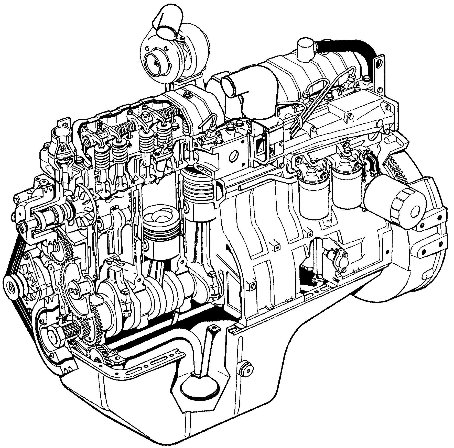
The 620 series CNH diesel engines are watercooled, four stroke, in-line engines with direct injection. All models are equipped with wet, replaceable cylinder liners, an exhaust turbocharger and charge-air cooling (air/air). As the engines are equipped with an electronic diesel control systemin conjunction with an electronic engine control system (CAN network including solenoid valve-controlled distributor injection pump VP30), all models comply with the exhaust-gas regulations in accordance with Tier 2.
Cylinder block
The rib-reinforced cylinder block forms the main engine unit, onto which other engine components are mounted.
The wet, replaceable cylinder liners are supported in the middle, thus reducing vibration and the coolant flow is mainly directed to the upper section of the cylinder liners.
The bottom part of the cylinder liner and the cylinder block are sealed by three O-rings, which are inserted in the grooves in the cylinder liner. The upper part is sealed by the cylinder head gasket.
The camshaft is located in the cylinder block. Allcamshaft bearings are equipped with replaceable cylinder liners.
Guide bearings are fitted on both sides of the rear crankshaft bearings (crankshaft – axial bearings).
Flywheel casing
The flywheel casing is fitted at the rear end of the cylinder block. The seal for the rear end of the crankshaft is fitted in a bore hole in the casing. The flange for the starter is located in the flywheel casing. The underside of the flywheel casing is used as a sealing surface for the oil sump seal. This means that the underside of the cylinder block must be flush with the flywheel casing. When the flywheel casing is fitted, its position is determined by sprung dowel pins.
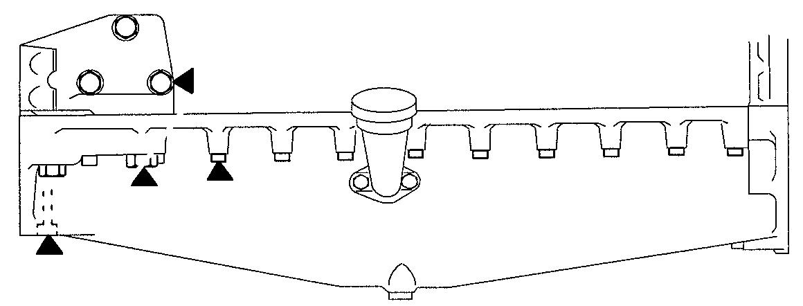
Cylinder head
The engines are equipped with two interchangeable cylinder heads. Each cylinder has its own intake and outlet channels in the cylinder head. To compensate for thermal stress, an inlet valve is fitted between the outlet valves
The cylinder head bolts are high-tensile pretensioned bolts, which are tightened to their elongation limit in accordance with the angular tightening principle. Due to the high degree of elongation, the retaining power is kept constant throughout the entire service life, and the bolts do not therefore have to be check tightened.
The injection nozzle seats are integrated into the cylinder head. The inlet and outlet valve guides are identical and can be interchanged. Furthermore, the in/outlet valves are fitted with replaceable valve seat inserts.
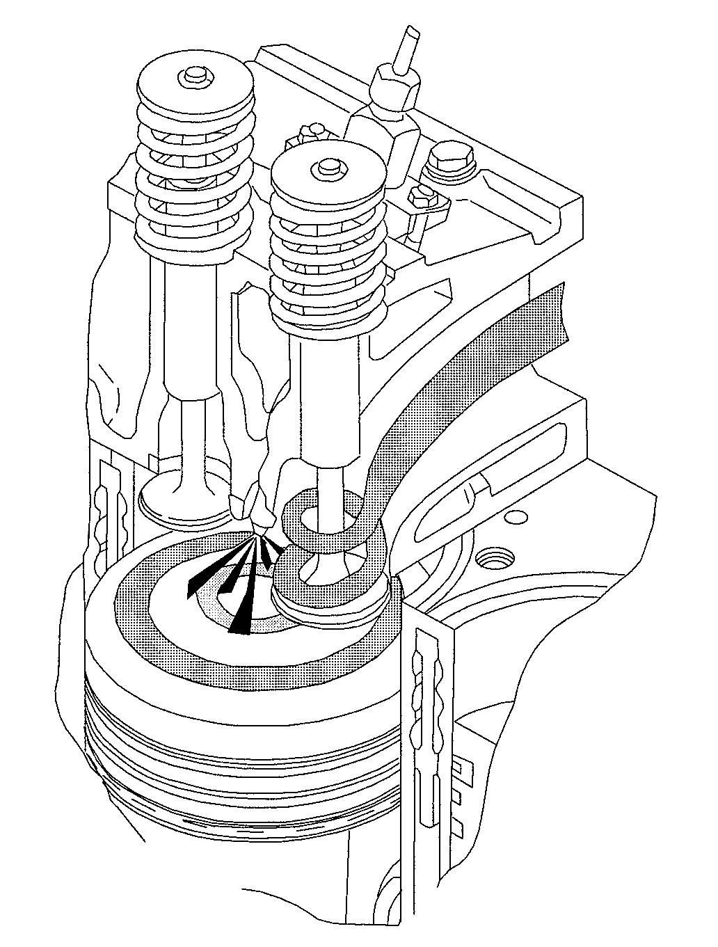
Valve mechanism
The valve mechanism is operated by the camshaft in the cylinder block. The drive power is transferred via valve tappets and push rods. The camshaft gear wheel is force fitted on the camshaft and fixed (radially) by a feather key. The bearings are lubricated with pressure oil through bore holes in the engine block.
Crankshaft drive
The crankshaft is made from forged chrome alloy special steel and the bearing and sealing surfaces are inductively tempered. The bearing points can be re-ground four times without having to be retempered. The gear wheels are force fitted at the front end of the crankshaft. They are used to drive the camshaft, injection pump and oil pump. In addition, the front end of the crankshaft has key-ways for seating the drive hub. The V-belt pulley and the torsional vibration damper (with rubber element) are fitted on the hub. The front PTO shaft (if fitted) is also driven via this hub. An oil deflector ring is fitted between the hub and gear wheel and a dust seal is fitted on the hub to protect the crankshaft sealing ring. The transmitter wheel for the engine speed sensor is fitted on a crankshaft web.
A crankshaft bearing is located on both sides of each cylinder. There are thus seven crankshaft bearings. The crankshaft axial bearings are located on both sides of the rearmost crankshaft bearing. The flywheel is mounted at the rear end of the crankshaft and carries a force fitted crown gear.
The forged con-rods have an I-shaped cross-section. The con-rod bearing is split horizontally. The bearing cover is secured by means of two special bolts. The upper part has a wedge-shaped bearing seat in which the small end bearing bush is force fitted.
The piston is made of an eutectic aluminium alloy. There is a combustion space in the piston head. The shape of the optimised combustion space ensures an optimal carburetion of air and fuel. The pistons have different types of piston rings depending on the engine type (see next paragraph).
The pistons are equipped with two compression rings and an oil scraper ring. In the case of engine types 620.95 and 620.96, the top molybdenum-coated piston ring has a rectangular cross-section. Engine types 620.97, 620.98 and 620.99 have a top piston ring with a trapezoidal cross-section.
The middle piston ring is a taper face ring (the outer diameter has a conical surface).
The oil scraper ring is sprung and has two chromeplated scraping edges.
The pistons are ring carrier pistons (the piston has a special cast iron ring carrier cast into it to seat the top piston ring). The friction surface of the piston skirt also has a graphite coating to ensure optimal running-in.
In the case of engine types 620.97, 620.98 and 620.99, the piston head is cooled from below by additional oil spray as soon as the oil pressure exceeds 3 bar.
Timing gears
The engine control gear wheels are hardened in the area of contact and have a helical gearing. The gear wheels are located in the timing gear case, which is fitted at the front of the engine. The timing gears drive the camshaft, the fuel injection pump and the oil pump. The intermediate wheel runs in pressure-lubricated friction bearings (like the camshaft). The bearing journal is fixed to the front surface of the cylinder block.
Lubrication system
1.Lubrication oil pump
2.Oil pressure valve
3.Oil filter
4.Turbocharger
5.Main oil duct
6.Oil spray nozzles
7.Oil pressure switch
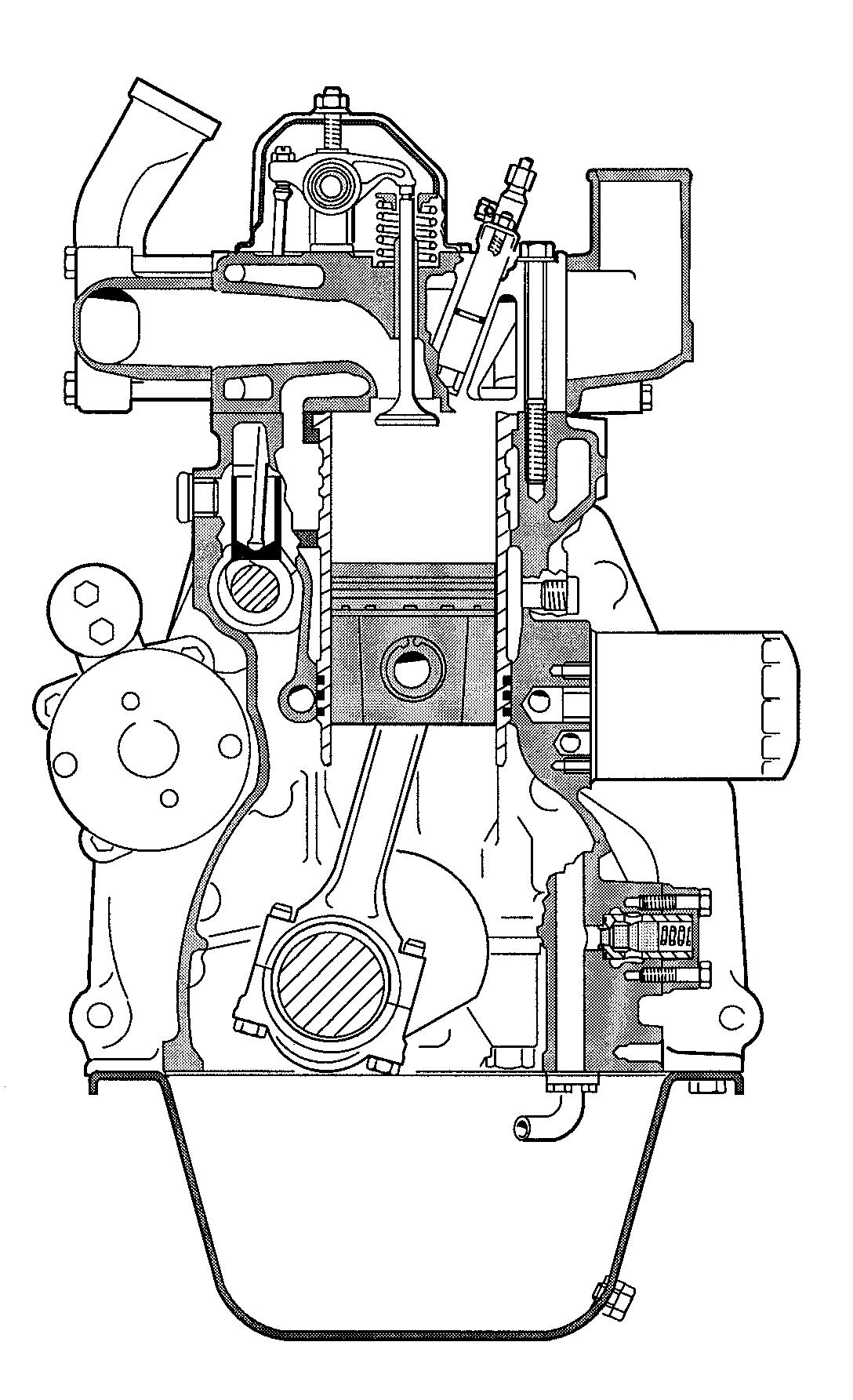
Lubrication system
The engine is equipped with a pressure lubrication system, in which the oil pump (gear pump) is fixed to the lower part of the cylinder block. The pump sucks the oil in via an intake sieve. From the pump, the oil is fed through an oil line to the oil cooler (heat exchanger) and to the oil filter. The oil pressure valve is located parallel. The oil is then fed into the main oil duct, from which other oil bores branch off. The oil flows through the oil bores to the crankshaft bearings and through the crankshaft to the con-rod bearings.
The pressure oil flows from the main oil duct to the turbocharger and to the air compressor (if fitted). In addition, the intermediate gear wheel bearings, camshaft bearings and valve mechanism are lubricated with pressure oil via the main oil duct.
In the case of engines 620.97, 620.98 and 620.99, the piston heads are sprayed with oil from below and cooled as long as the lubrication oil pressure is higher than 3 bar.
The oil pressure valve regulates the lubrication oil pressure so that a constant value is maintained independent of the engine speed. Depending upon the grade of oil, the engine speed and temperature, the oil pressure lies between 2.5 - 5 bar. The oil pressure must be at least 1.0 bar at idling speed.
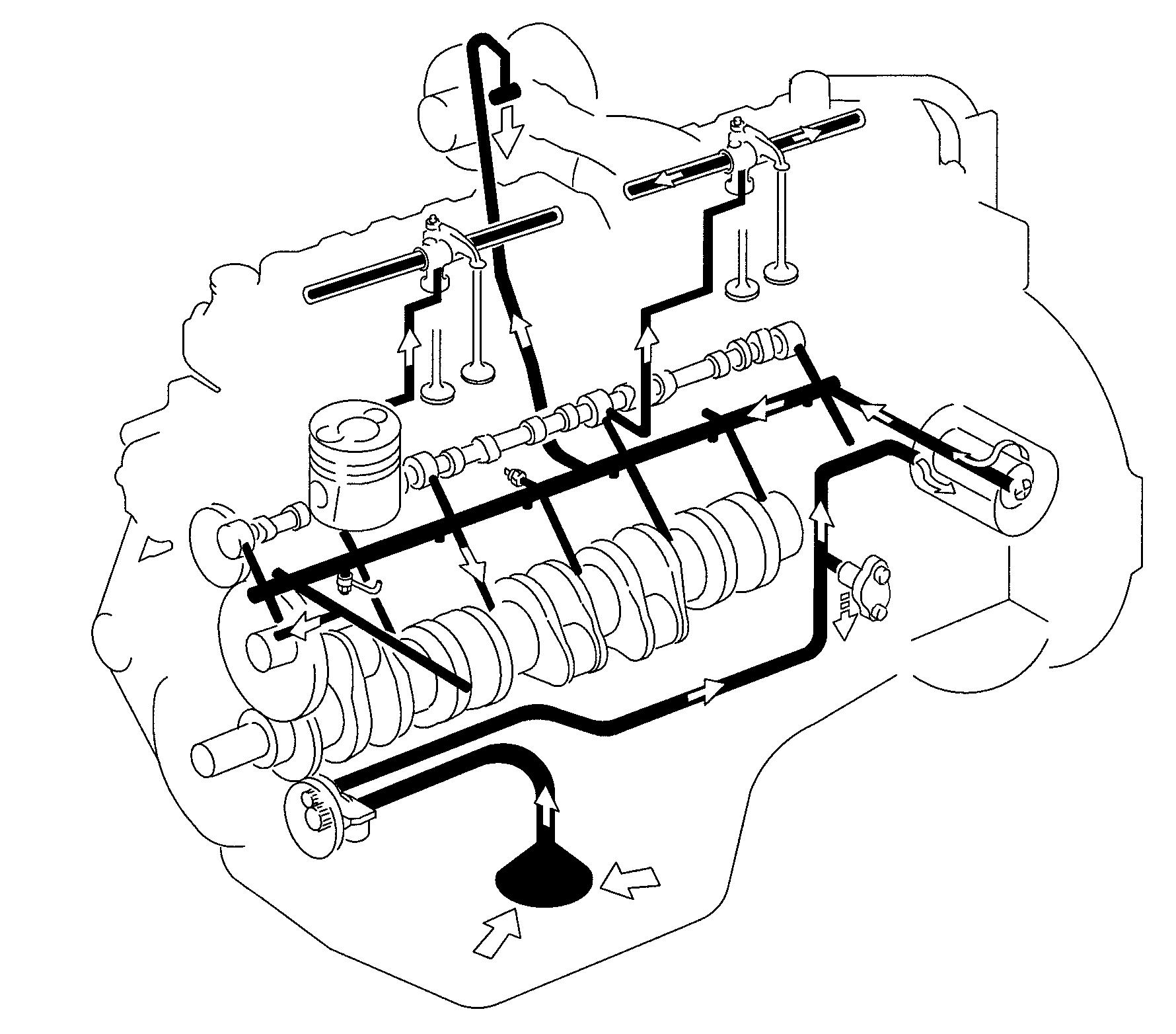
The oil filter is a one-way main stream filter. An overflow valve, on the underside of the filter, ensures reliable engine lubrication after cold starting at extremely low outside temperatures and sufficient lubrication in the event of a filter blockage. A nonreturn valve prevents the filter being completely drained of oil after switching off the engine.
The oil pressure switch opens at a pressure of >0.5bar.
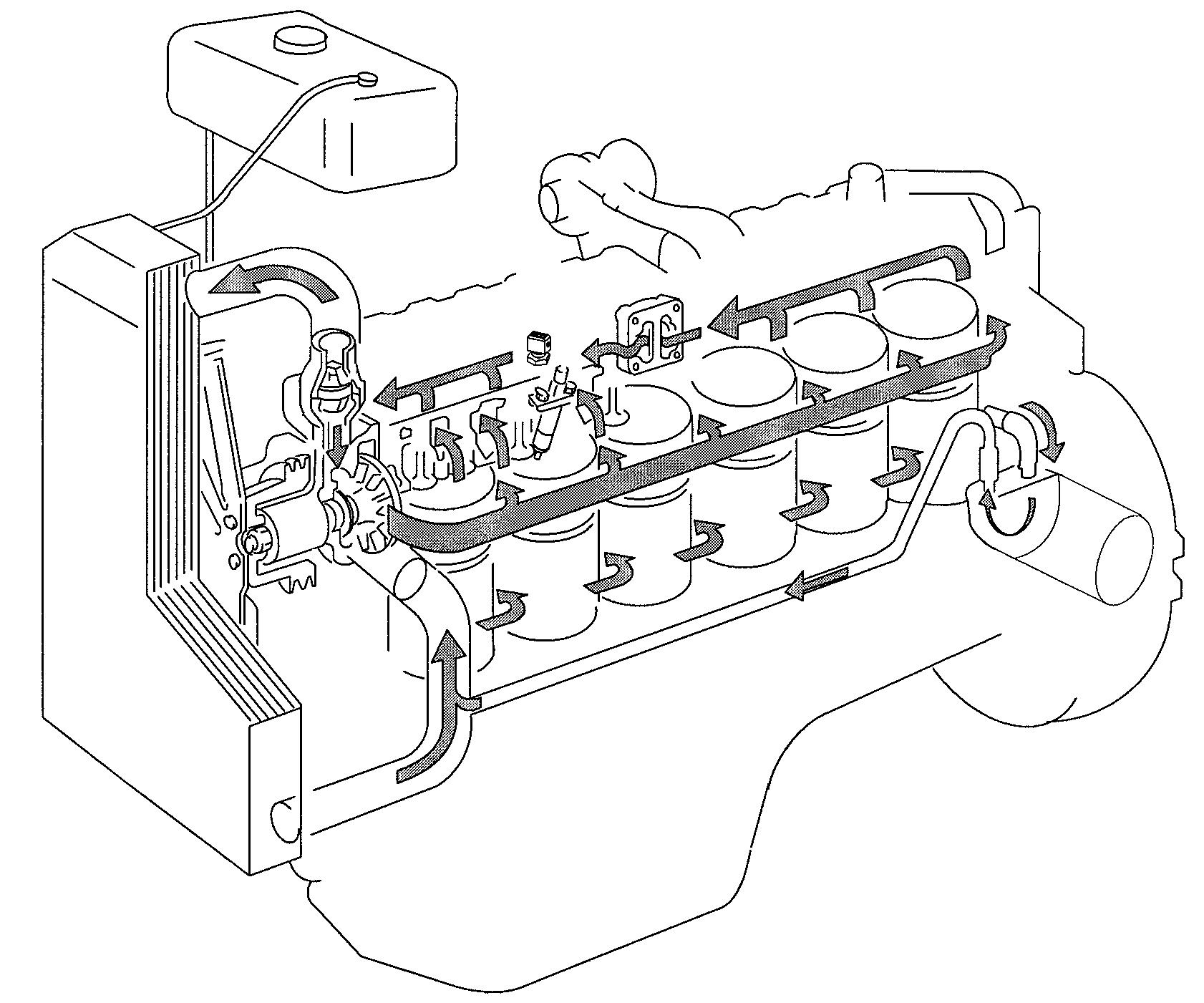
5.Expansion
6.Oil
7.Engine
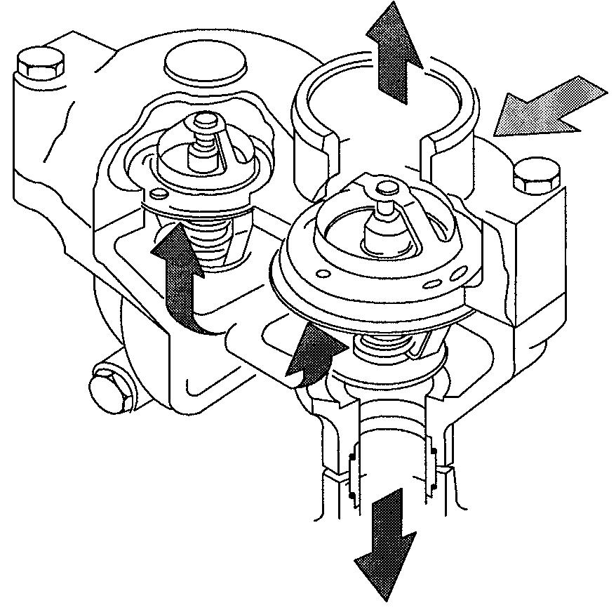
Cooling system
The belt-driven coolant pump is located at the front end of the cylinder block. The thermostat housing is situated above the pump. The cooling system is equipped with two thermostats, which control the coolant flow. The thermostats have different opening temperatures. If the coolant temperature lies below the opening temperature, the coolant (A) circulates back to the coolant pump via the bypass channel. The smaller, single-action thermostat (1) starts to open at 79 °C and lets some of the coolant(B) flow into the radiator. When the engine temperature increases, the dual-circuit thermostat(2) also starts to open at 83 °C. It closes the bypass when it opens and allows all the coolant (C) to flow into the radiator.
Thank you very much for your reading. Please Click Here. Then Get COMPLETE MANUAL.NOWAITING

NOTE:
If there is no response to click on the link above, please download the PDF document first and then clickonit.
