
20 minute read
A comparative study in flexure and shear design of spread footings


“Journal of Engineering Sciences”
Original Article
Advertisement
DOI: https://doi.org/10.22463/2011642X.2364
Estudio comparativo en el diseño a flexión y cortante para zapatas corridas MSc. Iago Freitas de Almeida1, DSc. Maurício C. B. de Noronha Campos2 , DSc. Romilde Almeida de Oliveira3
1 Doctorate Student, Universidade de Brasília, Brazil, Orcid: 0000-0002-8002-0591, Email: iago.freitas@hotmail.com / 170094511@aluno.unb.br 2 Professor, Universidade Estadual do Piauí, Brazil, Orcid: 0000-0003-4433-2798, Email: mcbncampos@gmail.com / mauriciocastelo@ctu.uespi.br 3 Professor, Universidade Católica de Pernambuco, Brazil, Orcid: 0000-0002-67869080, Email: romildealmeida@gmail.com How to cite: I. F. Almeida, M. C. B. N. Campos & R. A. Oliveira, “A comparative study in flexure and shear design of spread footings”, Revista Ingenio, 16(1), pp.23-29,2019 Received date: 05 de julio 2018 Approval date:25 de octubre de 2018
ABSTRACT
Keywords:
Design, Flexure, Reinforced Concrete, Shear, Spread Footings. The design of spread footings is a field widely explored in structural engineering being the flexure and shear design verified by the use of codes. The objective of this paper consists in a comparative study of spread footing design between the Brazilian’s code, Eurocode and American’s code. The methodology considered an analytical analysis with three different examples in the flexure and shear design of the spread footings with different loads and footing height. The results show that the American’s code presented the minimum required value of reinforcement rates in all examples and also was the only code that verified the punching and shear effect for all studied cases. In Eurocode flexure design, the results show that in the most examples, the reinforcement rate is higher than that considered by the other codes. The Brazilian code presented an inconsistency in the verification of the punching effect for one of the studied examples, requiring, therefore, a review and a modification of the code.
Palabras clave:
Diseño, Flexión, Concreto armado, Cortante, Zapatas corridas.
RESUMEN
El diseño de zapatas corridas es un campo ampliamente explorado en la ingeniería estructural siendo el diseño a flexión y cortante verificado por el uso de códigos. El objetivo de este trabajo consiste en un estudio comparativo del diseño de zapatas corridas entre el código brasileño, el Eurocódigo y el código americano. La metodología consideró un análisis analítico con tres ejemplos diferentes en el diseño de flexión y cortante de las zapatas corridas con diferentes cargas y altura de la zapata. Los resultados muestran que el código americano presentaba el valor mínimo requerido de tasas de refuerzo en todos los ejemplos y también era el único código que verificaba el efecto de punzonamiento y cortante en todos los casos estudiados. En el diseño a flexión de Eurocode, los resultados muestran que en la mayoría de los ejemplos, la tasa de refuerzo es más alta que la considerada por los otros códigos. El código brasileño presentaba una inconsistencia en la verificación del efecto de punzonamiento para uno de los ejemplos estudiados, requiriendo por lo tanto, una revisión y una modificación del código.
1. Introduction
According to [1], the spread footing that is used today emerged in the middle ages with the development of gothic architecture, and consequently the individual columns. Until the 19th century, many footings were built of masonry. The evolutions of architecture, calculation methods, and materials used have resulted in tall buildings with high loads [1]. Thus, more difficult cases of footings brought greater interest in this area.
Currently, in engineering footings, many tests are carried out to improve the current calculation models. The emergence of computational technology allowed automation through numerical methods. In this way, the use of software has become a very important tool for the engineer footings. However, even with the use of computational methods, there is a need to check existing codes on the market, and they may present differences regarding their respective methodologies.
In this work, the criteria adopted in the footing design by the Brazilian code (NBR 6118 [2], 2014) is compared with the criteria of Eurocode 2 [3] (2010) and with the American code (ACI-318 [4], 2014) in order to analyze possible divergences. Differences in flexural reinforcement rates and shear strength can, therefore, result in uneconomic footings or high stresses. In this way, the Eurocode 2 [3] is considered with [5] and the ACI-318 [4] is considered with [6].
2. Stiffness and Design
This section presents notions of spread footings design and stiffness for NBR 6118, Eurocode 2 and ACI 318. 2.1 Spread Footings Stiffness One of the classifications of great interest in footings
Corresponding autor Revista Ingenio, 16(1), Enero-Diciembre 2019, ISSN 2011-642X – E-ISSN 2389-864X E-mail ad: iago.freitas@hotmail.com (Iago Freitas de Almeida) Peer review is the responsibility of the Universidad Francisco de Paula Santander Ocaña This is an articule under the license CC BY-NC (https://creativecommons.org/licenses/by-nc/4.0/deed.es) 30
design is the stiffness. The Brazilian code NBR 6118 [2- 7- 8] classifies them as rigid and flexible footings. 2.1.1 Rigid Footings. According to NBR 6118 [2], rigid footing is defined when the footing height (h) is greater than 1/3 of the distance between one of the faces of the column and one of their extremity (see Figure 1) in both directions. The footing height (h) is given by Equation (1) as:
(1)
in which, a is the footing dimension in one direction and a0 is the column dimension in the same direction of a. (Figure 1.)
Figure 1. Spread footing model for NBR 6118 [2]. Source. [9].
In the case of Eurocode 2 [3-5], rigid footing is defined as those whose edges are less than twice the footing height (Figure 1). Thus, the definition consists of a height greater than 1/4 of the distance between the faces of the columns and their extremities in both directions. The edge (l) and the height (h) are defined by Equations (2) and (3) as:

According to [6], there is no footing classification in terms of stiffness for ACI-318 [4].
In [5], is also reported that in the case of rectangular footings, the use in one direction of edges with dimensions smaller than 2h and the other direction with dimensions greater than 2h is frequent. In this case, the footing is considered flexible. 2.2 Footing Design This section presents notions in flexure and in shear design of spread footings.
2.2.1 Flexural Design. The methodology applied to flexure design of spread footings is considered for NBR 6118, Eurocode 2 and ACI 318.
• Design according to NBR 6118. According to NBR 6118 [2], a rigid footing works in both directions. Thus, for each direction, the traction stress is considered uniform in the width of the footing. In the case of compression stress, the stresses are concentrated in the column region. The rigid footings [10] have reinforcement area (As) determined by Equation (6) as:

in which, Yf is the action-increase factor, Mk is the characteristic moment in the calculation section according to [10], d is the useful height and fyd corresponds to the design yield strength of the reinforcement. In case of flexible footings, NBR 6118 [2] declares that the distribution of the traction stress is not uniform in the footing width. In flexure analysis, the flexible footing works in both directions and should be assessed for the concentration of flexion near the column. The characteristic moment is calculated by the methodology of [10] for rigid and flexible footings (Figure 2).
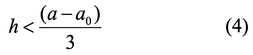
2.1.2 Flexible Footings. NBR 6118 [2] defines a flexible spread footing when the height is less than 1/3 of the distance between the faces of the columns and their extremities (see Figure 1) in both directions. The footing height (h) is defined by Equation (4) as:
In Eurocode 2 [3-5], flexible spread footings is defined as those whose edge (l) is greater than twice the height. Thus, the footing height is less than 1/4 of the distance between the faces of the columns and their extremities in both directions (See Equation (5)).
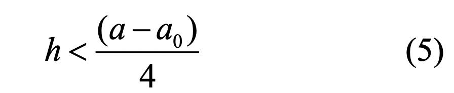
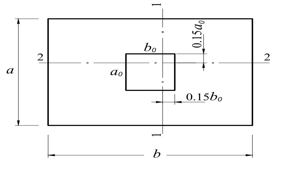
Figure 2. Actuate Moment according to [10]. Source. [11]. In Figure 2, sections 1-1 and 2-2 correspond to the region of operation of the characteristic moments. These sections operate at a distance of 0.15a0 and 0.15b0 of the column. The dimensioning of flexible footings according to NBR 6118 [2] follows the flexure model determined by tables of [12].
Revista Ingenio, 16(1), Enero-Diciembre 2019, ISSN 2011-642X – E-ISSN 2389-864X 31
• Design according to Eurocode 2 Eurocode 2, [5] considers the strut-and-tie model for rigid footings. According to [5], the model requires the effective functioning of the tie over his entire length. The reinforcement area is given by Equations (7) and (8) as:
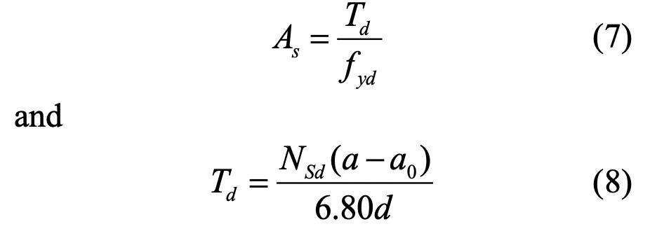
in which, Td is the design force on the ties, NSd is the axial design force and d is the useful height. In flexible footings design, the moment acts in section 2-2 and in section 1-1 (see Figure 2). The reinforcement areas (As) is defined by Equations (9) to (11) as:
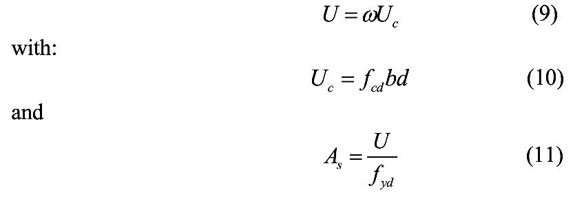
where, U is the steel mechanical strength, Uc is the concrete mechanical strength, ω is the mechanical rate, fcd is the compressive strength of concrete, and b is the footing dimension (see Figure 2).
• Design according to ACI 318 The verification of the flexural reinforcement is performed in both directions due to a critical section. In squared footings with rectangular columns, the critical section is determined on the face of the column. According to [6] in square footings, the distribution of the reinforcement must be uniform in both directions. In the case of rectangular footings, there is a concentration of the reinforcement close to the column. Thus, the calculation of square and rectangular footings is determined by Equations (12) and (13) as: 2.2.2 Shear Design. In this section is presented the shear criteria methodology for NBR 6118, Eurocode 2 and ACI 318.
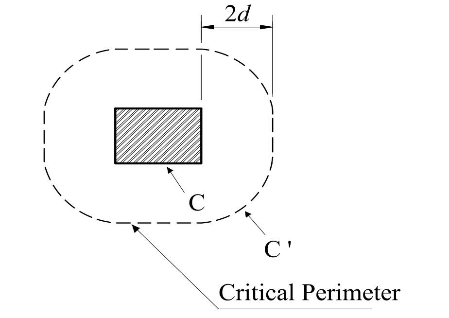
• Design according to NBR 6118 The model adopted by NBR 6118 [2] consists of checking the shear on two or more critical surfaces. The first critical surface (contour C) is on the face of the column and the diagonal compression stress of the concrete must be checked through the shear stress. The second surface (contour C’) is “2d” away from the face of the column and must be checked for resistance to diagonal traction through a shear stress. The respective critical surfaces C and C’ can be seen in Figure 3.

Figure 3. Critical perimeter of internal columns. Source. [2].
In Figure 3, the contour C corresponds to the shear force analysis and the contour C’ corresponds to the punching rupture analysis. According to NBR 6118 [2], in rigid footing, the shear acts in both directions with only the need to check the diagonal compression. In traction diagonal strength, there is no need to check it, because this phenomenon does not represent a risk of rupture. Moreover, the diagonal compression is located inside the hypothetical punching cone and the diagonal traction outside it. Thus, in rigid footings only the contour C should be checked.
In flexible footings, the NBR 6118 [2] affirms that the effect of the shear force is verified by the diagonal compression and the verification of the punching is performed for the diagonal traction. Therefore, the verification must be carried out on the contours C and C’. In this item, NBR 6118 presents an inconsistence, since the inclination for classification as to stiffness is different from the inclination of the punching cone and there may be cases in which the footing is classified as flexible and yet is still inside the punching cone (Figure 4).
where, Md is the required moment, fyk is specified yield strength of the reinforcement, Ψ is a strength reduction factor that assumes values of 0.90, and j is a dimensionless ratio equal to 0.95.

Figure 4. Punching cone inclination and stiffness limit inclination.
Revista Ingenio, 16(1), Enero-Diciembre 2019, ISSN 2011-642X – E-ISSN 2389-864X 32
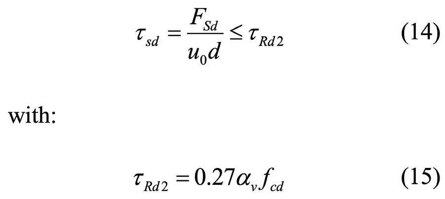
In contour C (see Figure 3), NBR-6118 [2] establishes that for an internal column with symmetrical loading, the required shear stress (τsd) must be less than or equal to the resistant stress of diagonal compression of concrete on surface C (τRd2) given by Equations (14) and (15) as:
where, FSd is the calculating force for shear and punching analysis, αv = (1 - fck / 250) with fck in MPa and u0 corresponds to the critical perimeter in contour C according to Figure 3. The verification of punching rupture (Contour C’) is given by NBR 6118 [2] for structural elements without punching reinforcement by Equations (16) and (17).
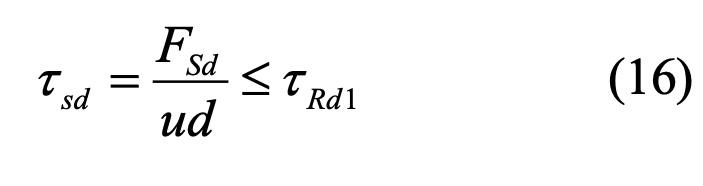

in which, τRd1 is the diagonal traction strength of concrete on the surface C’ and ρ is the geometric rate of flexure reinforcement. In the presence of capitals (variable height footings), NBR 6118 states that the verification of the same must occur in the contours C’1 and C’2 as indicated in Figure 5.
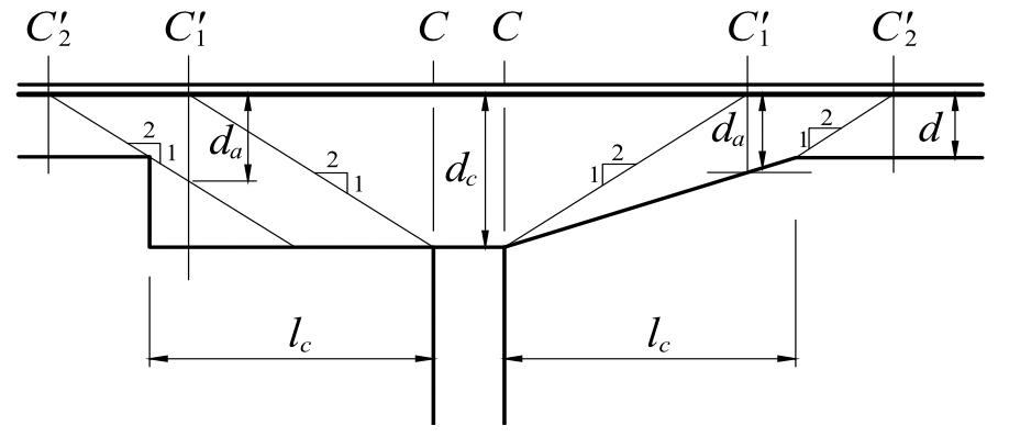
Figure 5. Critical perimeters in capitals. Source. [2].
In Figure 5, d is a useful height of the section for capitals applied in the C’2 contour, dc is a useful height on the face of the column; da is a useful height in the C’1 contour and lc is a distance between an edge of the capital and a face of the column. In the design of spread footings with capitals, the value of lc must be compared to the dimensions dc and d. According to NBR 6118 [2], if lc < 2(dc - d), only the C’2 contour is verified. However, if 2(dc - d) ≤ lc ≤ 2dc, only the C’1 contour is verified. Otherwise, if lc >2dc, both contours must be checked.
• Design according to Eurocode 2: The shear rupture must be checked in two ways. The first verification is in a single direction, due to a shear force and the second verification in both directions, due to the punching effect. However, shear effect should only be analyzed on flexible footings. In [5], the verification of the shear is made for the largest footing dimension. The shear effect is given by Equations (18) to (22) as:
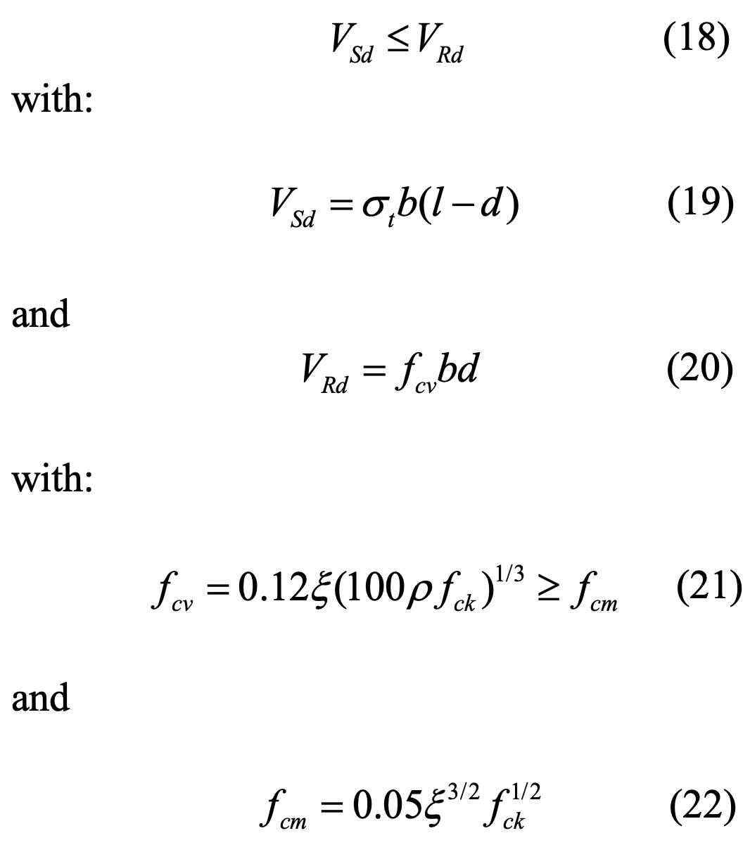
in which, VSd is the calculating shear force, VRd is the ultimate shear force, σt is estimated soil stress and fcv is the virtual shear resistance, fcm is the minimum virtual shear resistance with ξ = 1 + (200 / d) 1/2 with d in millimeters. The punching effect for [5] is considered in footings with flexion in two directions and will depend on a critical section at a distance of “2d” from the face of the column. Consequently, the critical section is similar to that adopted by NBR 6118 [2]. The punching effect is verified by Equations (23) and (24) as:

Revista Ingenio, 16(1), Enero-Diciembre 2019, ISSN 2011-642X – E-ISSN 2389-864X 33

in which, τSd is the punching shear stress, fcv is calculated by Equation 21, uc is the critical perimeter [5] and FSd is calculating force for punching.
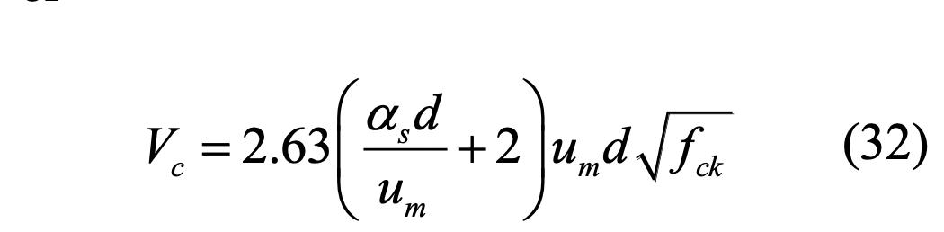
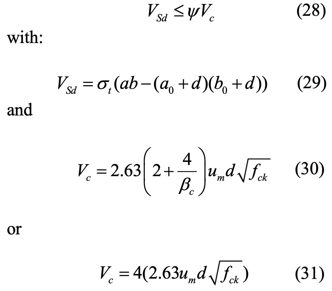
• Design according to ACI 318 In [6], the shear verification is for one and two directions. In one direction analysis, the verification is by shear force effect where inclined cracks happen along the footing width. where, βc is the ratio between the largest and smallest column dimensions, um is the critical perimeter [6] given as um = 2(a0 + d) + 2(b0 + d) , d is the useful height, αs is equal to 40 for a centered column. The choice of the Vc is given by the minimum value of Equations (30) to (32).
The ACI 318 [4] affirms that the shear rupture in one direction is decisive in the combined and rectangular footings. The design is similar to that of flat beams and must be verified. The shear effect in one direction is given by Equations (25) to (27) as:
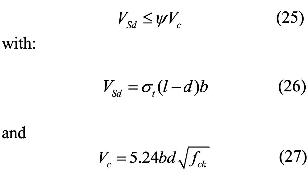
in which, VSd is the shear force between a distance d from the column surface and the footing edge (See [6]), Vc is the shear strength force with fck in kN/m², σt is the estimated soil stress, Ψ is strength reduction factor equal to 0.75 and l is the edge of the footing dimension to be analyzed. The two directions shear verification is for punching effects. The punching shear effect is detected by cracks in the pyramid shape. The verification of the punching effect [6] must satisfy the Equations (28) to (30).
3. Analytical examples
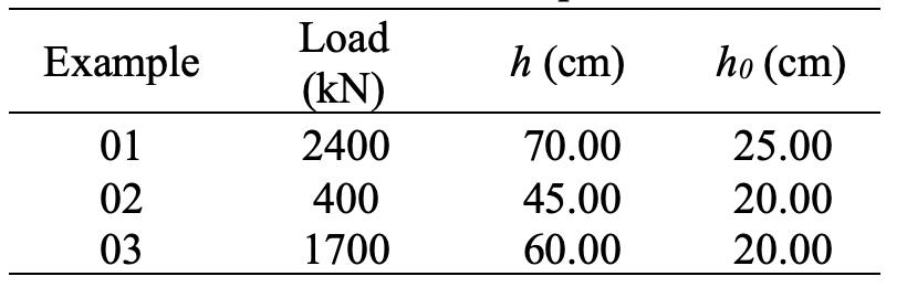
Three dimensioning examples of rigid and flexible spread footings is be presented with fck =30 MPa, using the processes presented in the previous item. In the first example, the footing is rigid for NBR 6118 and Eurocode 2. In the second example, the footing is flexible for both. In the last example, the footing is flexible for NBR 6118 and rigid for Eurocode 2. Moreover, the design of ACI 318 is considered in the three examples, regardless of rigidity. In Table 1 is shown the parameters for these examples.
Table 1. Parameters for examples.
In Table 1, each example has different loads and heights that influence the stiffness of the footings. The width and length dimensions are shown in Figure 6.

Figure 6. Design examples (Measurements in Centimeters).
Revista Ingenio, 16(1), Enero-Diciembre 2019, ISSN 2011-642X – E-ISSN 2389-864X 34
In Figure 6 and Table 1, it is observed that all examples have the same plan dimensions. The only change is considered in load and footing height.
4. Results and discussion
The results of the flexion design are shown in Table 2 with ASa corresponding to the reinforcement rate for the dimension a = 270 cm and ASb corresponding to the reinforcement rate for the dimension b = 215 cm . The reinforcement values considered by the [6] model in all cases were the minimum. In Table 2, the reinforcement areas calculated by NBR 6118 for example 01 showed differences to the Eurocode 2 with a relative error between 16 and 24%. The values of NBR 6118 when compared with the method of ACI 318 showed a relative error in the largest direction equal to 17% and in the smallest direction to 2%.
Table 2. Flexural design. is no need to verify the shear and punching effects. However, for ACI 318, the τSd is practically equal to maximum resistant capacity τc.
In Example 02 Table 3, the shear force considered by Eurocode 2 and by ACI 318 corresponded to 25% (approximately) of the maximum resistance capacity of each code. However, when verifying contour C, the VSd had reached less than 15% of the maximum capacity VRd2. In punching effect, NBR 6118 was the most discerning. The stress due to diagonal traction (Contour C ’) was at the limit of the footing capacity.
Table 3. Shear design.

In Example 02, the reinforcement areas of NBR 6118 showed higher magnitudes than those of Eurocode 2. The relative error was between 20% and 22%. However, the relative error, when compared to ACI 318, was 62%. In Example 03, the reinforcement areas of NBR 6118 were smaller than those of Eurocode 2 with a difference between 39% and 49%. For the ACI 318, the reinforcement presented a maximum relative difference value, when compared to NBR 6118, in the smallest direction of 20%. The shear effect is shown in Table 3.
In Table 3, the Example 01 shown that for NBR 6118, the VSd corresponds to a half of the resistance capacity VRd2. In case of ACI 318, the verification is performed in the format of the requesting force represented by approximately half of the footing resistant strength.
Table 3 also shows that in Example 01, there is no punching rupture for NBR 6118. For Eurocode 2, there (-) Do not verify.

In Table 03, the τSd for punching effect of Example 02, considered for Eurocode 2 and ACI 318 values between 37 and 39% of the resistance stress of each code, respectively. In Example 03, the shear force of ACI 318 model reached half of the maximum capacity. In NBR 6118, the contour C presented 46% of the footing resistant capacity. However, the verification of diagonal traction has become impossible, as the flexible footing is located inside the hypothetical punching cone. In case of ACI 318, the τSd reaches the maximum punching resistance capacity. The Example 03 also shows an inconsistency in the punching effect for NBR 6118. This inconsistence is demonstrated in Figure 7.
Revista Ingenio, 16(1), Enero-Diciembre 2019, ISSN 2011-642X – E-ISSN 2389-864X 35
Figure 7. Contour C’1 for NBR 6118.
In Figure 7, the contours C’1 and C’2 are outside the footing dimensions and, therefore, there is no verification adopted by the Brazilian code. Thus, a new methodology is necessary for it.
5. Conclusion
In flexural design, the reinforcement areas, in examples 01 and 03, resulted in values greater than the minimum for both NBR 6118 and Eurocode 2. However, in all cases the reinforcement rates of ACI 318 were minimal.
In Example 02, the reinforcement areas dimensioned by NBR 6118 allowed values closer to those of Eurocode 2 than those of ACI 318. In Examples 01 and 03, the values of ACI 318 are close to those of NBR 6118 and lower than those of Eurocode 2. The shear design was determined by the height of the footing and consisted of checking the resistance to shear and punching criteria. The criteria adopted by NBR 6118 are considered rigorous and through the examples shown it was possible to foresee inconsistency in their dimensioning. The slopes considered by it allow flexible spread footings within the hypothetical punching cone. However, for Eurocode 2 in flexible footings, the classification inclination to stiffness coincides with the inclination of the punching cone so that there is no inconsistency.
The verification of the shear force by NBR 6118 consists only of the analysis of the diagonal compression stress, that is, the verification of the C contour. For Eurocode 2 and for ACI 318 the verification of the shear force is performed in one of the footing dimensions.
6. References
[1] E. L. Silva, “Análise dos modelos estruturais para determinação dos esforços resistentes em sapatas isoladas”. M.S. thesis, Universidade de São Paulo, São Carlos, EESC, Brazil, 1998. [2] Associação Brasileira de Normas Técnicas: NBR
6118 – Projeto de estruturas de concreto – Procedimento. Rio de Janeiro, 2014. [3] Eurocode 2, Design of Concrete Structures –
Part 1-1: General Rules and Rules for Buildings,
CEN, EN 1992-1-1, Brussels, Belgium, 2010, 255 pp. [4] ACI Committee 318, Building Code Requirements for Structural Concrete. Michigan: American Concrete Institute, Farmington Hills, 2014. [5] A. G. Meseguer, F. M. Cabré, and J. C. A. Portero: Jiménez Montoya – Hormigón armado. Barcelona: Editorial Gustavo Gili, SL, 15th edition, 2011. [6] J. K. Wight: Reinforced concrete – Mechanics and design. New Jersey: Pearson Prentice Hall, 7th edition, 2016. [7] Associação Brasileira de Normas Técnicas: NBR 6122 – Projeto e execução de fundações. Rio de
Janeiro, 2019. [8] U. R. Alonso: Exercícios de Fundações. São Paulo: Ed. Edgard Blüncher, 2013. [9] E. L. Silva, R. D. Vanderlei, and J. S. Giongo:
Concreto armado – Projeto estrutural de sapatas.
São Carlos: EESC – USP, SET 408, 2008. [10] H. Ishitani, J. C. D. Bella, and F. P. Graziano: Estruturas de Concreto III-Disciplina PEF – 313, class notes. São Carlos: Escola Politécnica –
USP, 1998. [11] P. S. S. Bastos: Estruturas de Concreto III-Disciplina 2133 – Sapatas de Fundação, class notes.
Bauru: UNESP, 2019. [12] L. M. Pinheiro: Fundamentos do concreto e projeto de edifícios. São Carlos: Departamento de
Engenharia de Estruturas, EESC, 2007.
Revista Ingenio, 16(1), Enero-Diciembre 2019, ISSN 2011-642X – E-ISSN 2389-864X 36


