PORTFOLIO
SELECTED WORKS 2018 - 2024 CONTACT a59hasan@uwaterloo.ca PHONE +12262017336
ALI HASAN
01
02
03
04
05
06
07
CONTENTS
PORTAL
URBAN
[p.4]
ACADEMIC Comprehensive Design Studio
JAMAICA [p.12]
LITTLE
Urban Design Studio
VALE
Orthopedic
THE
[p.17]
Hospital
Studio
INVERTED [p.21] Housing
[p.28]
Freelance
RESIDENCE
PROFESSIONAL
STATION
Design + Build
WINTER
[p.26]
MICROSOFT DATA CENTRE [p.30] Bim Modelling and Co-ordination
CONTACT


2262017336
hasan.javed1999@gmail.com

69 Grand Ave N, Cambridge, ON
SOFTWARE
BIM:
REVIT
NAVIS WORKS
ARCHICAD
MODELLING:
RHINO
AUTOCAD
SKETCHUP
VECTOR WORKS
RENDERING:
LUMION
ENSCPAE
D5
VRAY
PRODUCTION:
ADOBE SUITE
MID JOURNEY
AUTODESK FORMA
SKILLS
3D PRINTING
CONSTRUCTION
LASER CUTTING
WOOD WORKING
PHOTOGRAPHY
SUMMARY
ALI HASAN ARCHITECTURE STUDENT

A passionate Master’s of Architecture student, want to broaden my horizons as an intern. I seek to gain experience working on real world architecture projects, offering latest software techniques, fresh ideas and diligent teamwork.
EDUCATION Master of Architecture
University of Waterloo, Canada
Bachelor of Architecture
Amity School of Architecture and Planing, India
WORK EXPERIENCE AECOM
Architectural Intern
2023 - 2025
(Expected Date of Graduation)
2018 - 2023
06/2021 - 12/2022
BIM Modeling for Microsoft Data Center, Railway Terminal
University of Waterloo
Teaching Assistant
Assisting on Introduction to Global Business
Rathi Stelmax Industries
Part time Junior Architect
Working drawings for Residence
INVOLVEMENT
Winter Station Design + Build Competition
Commendation for Passing B.Arch Amity School of Planning and Architecture
Architectural journalism and Criticism Competition ADMA Magazine
62nd LIK Trophy on Architectural documentation NASA, India
Water, Public Space and The Medieval City of Udaipur Participated in Workshop by City Labs
01/2024 - ongoing
01/2023 -08/2023
2024 Winner
Bronze Medal
2nd Prize, Internationally
Top 10 India, Nationwide

15 December 2022
RE: Letter of Recommendation
To Whome it May Concern:
I am delighted to furnish this letter of recommendation for Ali Hasan, who was employed at the AECOM India office in Gurugram from June to December 2022.
Ali actively participated in projects under my supervision as the Design Director for the Architecture Department. His primary responsibilities included collaborating with intermediate project leads on the creation of Good for Construction drawings for several Data Centers. Additionally, he contributed to establishing the Schematic Design package for the Ahmedabad Railway Station. He also played a crucial role in coordinating with other departments to resolve clashes in BIM models. Furthermore, Ali was fortuante to get an opportunity to dedicated several weeks in collaboration with the U.K. office on the design of Data Center Templates for a Tech Giant, with an emphas design innovation, quality, and standards.
Having directly worked with Ali and observed his collaborative efforts with other team members, I can attest to his meticulous attention to detail and his ability to adapt swiftly to new working methodologies. He demonstrates proficiency in addressing challenges as they arise. Ali’s contributions were invaluable to the team, and his inquisitive and self-motivated approach undoubtedly lays a solid foundation for effective collaboration within any team environment.
Sincerely,
Partho Chakrabarti
Supervising Architect: COA Registration number:

AECOM Limited | 9th Floor, Infinity Tower C DLF Cyber City, DLF Phase II Gurgaon aecom.com
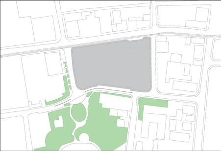
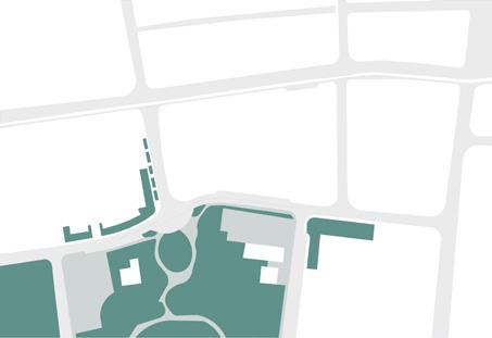
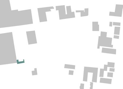
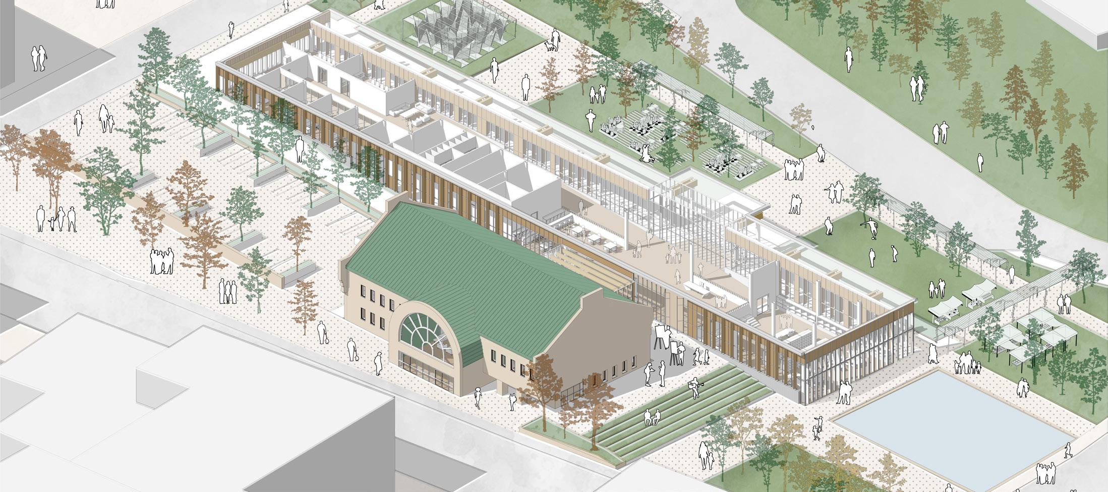
The once-old Bus Terminal is reborn, not just as a place, but as the heartbeat of our community. It’s not just a space; it’s a vibrant hub that seamlessly connects with Victoria Park and the lively Gaukel Street, creating a tapestry of possibilities. This transformation isn’t just about bricks and mortar; it’s about weaving a portal to a brighter, more interconnected community life. The Old Bus Terminal won’t just stand there; it will become an anchor to the spirit of our neighborhood, breathing life into every corner it touches.







Comprehensive Design Studio | Individual | Kitchener, Canada | 2023
RETAIL PEDESTRIAN STREET NATURE WALK URBAN PORTICO RECREATION PUBLIC
Creating
Extending
01 URBAN PORTAL Community Center
Adaptive reuse Bus Terminal as anchor
a linkage
to landscape Open space

RENDERED VIEW OF THE ADDITION
Adding complimentary building to the existing Bus terminal was a strategic design move focused on Adaptive reuse.

SOLID - VOID
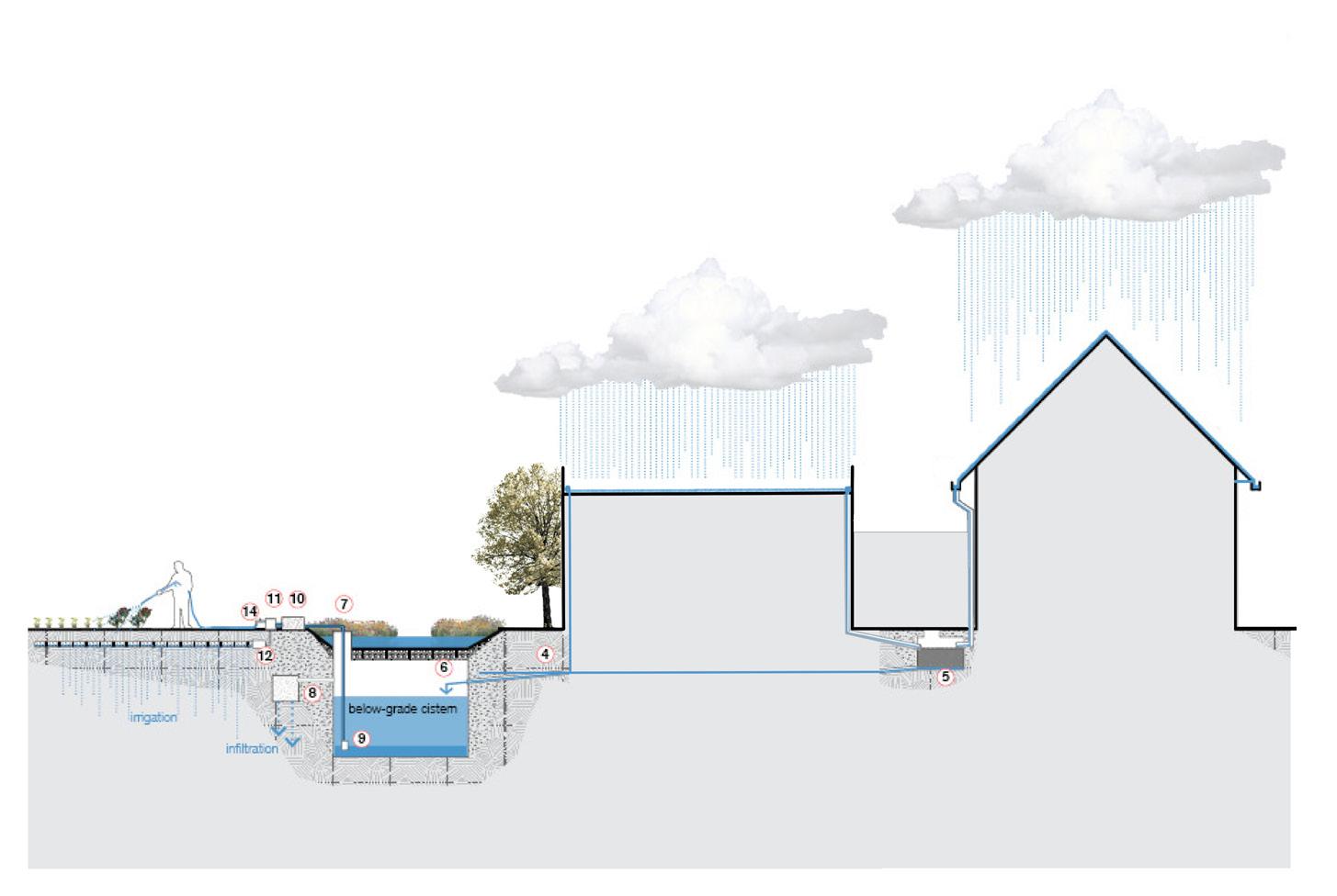
RAINWATER COLLECTION AXES
AXONOMETRIC
The Old Bust terminal and the new additional form are juxtaposed to establish a public realm. With one Axis which is open and flexible, the other which is intimate and allows for the use of interstitial spaces.
I Love the Art Street!! Community Shopping is so affordable. I enjoy spending my evenings @ fountain can spend all day in this library looking at this amaizing landscape Perfect place to throw ball. What a magical picnic spot! Look at that interesting Public Art installation Remember the Old Bus terminal! Wow, a space for community to actually engage with. Easy walk from shops to the community center. La La La La !!! The perfect flexible party!! Look at all this amaizing art work. Wow, a shortcut to my office, what a great walk. Son, lets sit outside and eat outsidy!

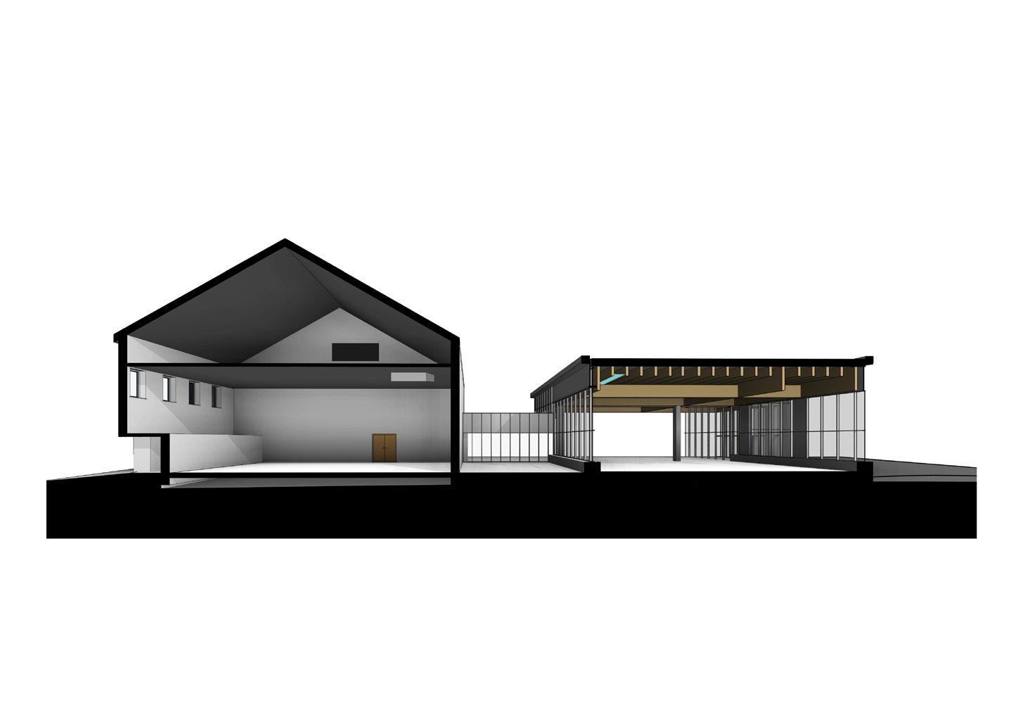
BUILDING STRUCTURE EXPLODED
LowSlopeRoof
GUTTER WITH LEAF SCREEN
Gutter + Leaf Screen
FRESH AIR FROM LARGE VENT
Fresh Air Vent
Coolant Supply
AIR EXHAUST
Air Exhaust
Fan Coil Unit
DOAS
FAN COIL UNIT
DOAS


Operable Windows
OPERABLE WINDOWS
Hot Air
HOT AIR


duct
Air Supply
AIR SUPPLY
SOLAR PV PANELS
duct Solar PV Panel


The HVAC system integrates geothermal energy with a VRF system for efficient and precise temperature control, aligning with sustainability goals. Geothermal heat exchange with the Earth ensures a stable thermal energy supply, enhancing energy efficiency and reducing environmental impact. This forward-thinking approach emphasizes reliance on renewable energy and minimizes traditional heating methods’ ecological footprint.
COOLANT SUPPLY -

UNDERGROUND CISTERN
Underground Cistern
COMPREHENSIVE DESIGN
As part of the studio, we had to design our chosen structural and system strategies to produce a proof of concept.
GEOTHERMAL WELLS
Geothermal Well
BUILDING SYSTEMS PERSPECTIVE SECTION
DUCT
DUCT
.S
ConcreteFoundation
GlulamBeams H
.SColumns ConcreteFloor
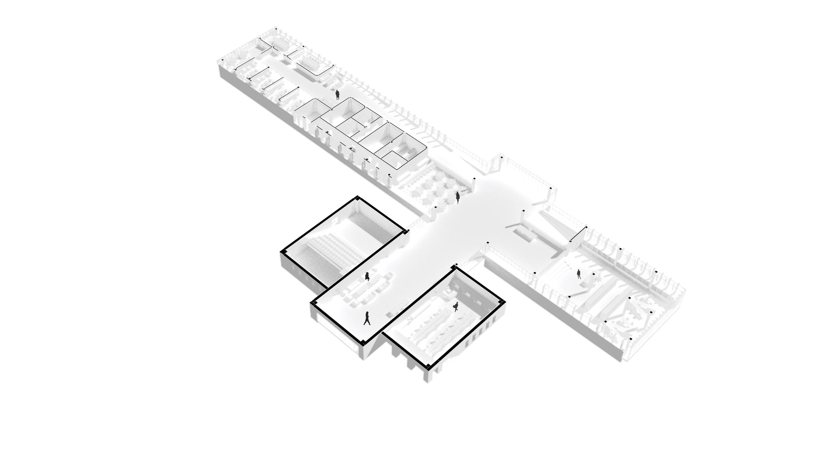
FLOOR PLAN GENERATORS
LEGEND
1. Auditorium
2. Foyer/ Flex space
3. Workshop
4. Gallery
5. Cafe
6. Kitchen 7. Services
8. Admin
9. Library
PROPORTIONS
The existing building is used as a generator for developing the extention. Using the large mass and the extrusion, the extention is stacked next to one another. The overall lenght of the extention is staggered, to obtain balance in the overall form

AXONOMETRIC PLAN
It was a strategic design move to keep the existing bus terminal building and propose a lite addition to it. Appropriated from sustainability as-well as the buildings connection with the community.
RECEIVING/STORAGE KITCHEN MECHANICAL RM RAMP UP ADMIN OFFICE ADMIN OFFICE CONSULTATION ROOM CONSULTATION ROOM ELECTRICAL RM +2.6 +0.6 +0.6 -0.0 FOYER AUDITORIUM WORKSHOP FOYER GALLERY CAFE LIBRARY ADMIN DEPARTMENT SEMINAR SEMINAR RECEIVING/STORAGE KITCHEN MECHANICAL RM RAMP UP ADMIN OFFICE ADMIN OFFICE CONSULTATION ROOM CONSULTATION ELECTRICAL RM +2.6 +0.6 +0.6 -0.0 FOYER AUDITORIUM WORKSHOP FOYER GALLERY CAFE LIBRARY ADMIN DEPARTMENT SEMINAR RECEIVING/STORAGE KITCHEN MECHANICAL RM RAMP UP ADMIN OFFICE ADMIN OFFICE CONSULTATION ROOM ELECTRICAL RM +2.6 +0.6 +0.6 -0.0 FOYER AUDITORIUM WORKSHOP FOYER GALLERY CAFE LIBRARY ADMIN DEPARTMENT SEMINAR RECEIVING/STORAGE KITCHEN RAMP UP +0.6 +0.6 -0.0 FOYER AUDITORIUM WORKSHOP FOYER GALLERY CAFE LIBRARY WORKSHOP AUDITORIUM FOYER GALLERY LIBRARY CAFE KITCHEN ZONING 0 5 10 1 A A B B B
a 2a
a A A-B B B B
3B
b
ADDITION RESPECTING PROPORTIONS 2 1 3 4 5 9 8 6 7


4x 0 5 10 1 20
FRONT ELEVATION
05 Building Enclosure Material Choices
DETAIL AT 4
DETAIL AT 3.1
CONSTRUCTION ASSEMBLY -
STRUCTURE: H.S.S WITH GLULAM BEAMS AND CLT ROOF SLAB
SUPPORT: METAL STUDS
CLADDING:
VERTICAL WOOD SIDING AND HANDSET PRECAST CONCRETE
OPENING: TIMBER WINDOW WALL DOUBLE GLAZED
ROOF: PROTECTED MEMBRANE ROOF WITH STONE BALLASTS
DETAIL AT 3.2
DETAIL AT 2
ENVELOPE DETAILS
ZINC FLASHING
PRECAST CONCRETE PARAPET WITH DRIP

150MM ROCKWOOL RIGID INSULATION (THERMAL BARRIER)
DRAINAGE GAP 30MM
STEEL STUD 150 MM
HORIZONTAL FURRING STRIP 30MM WIDE VERTICAL FURRING STRIP 30MM WIDE FOR DRAIN GAP
WOOD SIDING 50 X 30 VERTICALLY PLACE & LAPPED
CONTINUOUS FLEXIBLE FULLY ADHERED AIR+WATER+VAPOR CONTROL MEMBRANE
BALLAST
FILTER FABRIC
XPS ROOF INSULATION
150MM THICK BOTTOM GROVED FOR DRAINAGE GAP
TWO PLI CONTINUOUS FLEXIBLE FULLY ADHERED AIR+WATER+VAPOR ROOF CONTROL MEMBRANE
CLT ROOF SLAB 170MM THICK (5 LAYER) WITH 2% SLOPE
GLULAM BEAM 740MM DEEP
To propose a facade system which would be able to handle rain and thermal requirements of Canadian context, a perfect wall assembly has been used.
Yellow Cedar cladding torrefied and brushed
YELLOW CEDAR CLADDING
Yellow Cedar cladding torrefied and brushed

Handset Precast concrete
Handset Precast concrete
HANDSET PRECAST CONCRETE
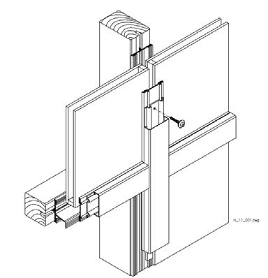
Window wall, Double glazed, Timber Profiled
WINDOW WALL SYSTEM
Window wall, Double glazed, Timber Profiled
ROOF TO WALL DETAILS 1 KITCHENER ENCLOSURE DETAILS 1:5 5/12/2023 UNIVERSITY OF WATERLOO CAMBRIDGE, O.N. CITY ALI Notes: REVISIONS: A WINDOW SIZE UPDATED AH 5/12/23 HASAN OF KITCHENER
ARCH671 A4
PARAPET DETAIL LVL (+2.8M LVL 3 (+3.1M LVL (+06M LVL 4 (+3.4M NORH ELEVATION SECTION
05 Building Enclosure Material Choices
LVL (+2.8M LVL (+3.1M LVL (+06M LVL (+3.4M NORH ELEVATION SECTION
4300 170 160 700 100 100 VARIES (ALWAYS BELOW THE FROST LINE) 600 E.Q. E.Q. 3000 (CLEAR OPENING) ENCLOSURE SECTION 1
N.G.L.
KEY PLAN 2 BUILDING ENVELOPE SECTION
05 Building Enclosure
Foundation details
DETAIL AT 4
Building movement and construction tolerances: The movements in the building and construction tolerences are taken care of using movement joints and maintiaining gaps between the Beams and the window, along with the rainscreen designed to overlap allowing for vertical as well as side expantion.
DETAIL AT 3.1
CONSTRUCTION ASSEMBLY -
STRUCTURE: H.S.S WITH GLULAM BEAMS AND CLT ROOF SLAB
SUPPORT: METAL STUDS
CLADDING:
VERTICAL WOOD SIDING AND HANDSET PRECAST CONCRETE
OPENING: TIMBER WINDOW WALL DOUBLE GLAZED
ROOF: PROTECTED MEMBRANE ROOF WITH STONE BALLASTS
DETAIL AT 3.2
DETAIL AT 2
ENVELOPE DETAILS
ZINC FLASHING
150MM ROCKWOOL RIGID INSULATION (THERMAL BARRIER
PRECAST HANDSET CONCRETE 125MM THICK

ZINC FLASHING METAL STUD 300MM WIDE
TYPICAL VS PROPOSED COST BREAKDOWN
ANGEL FASTENED TO FOUNDATION AND PRECAST CONCRETE WALL
CONTINUOUS FLEXIBLE FULLY ADHERED AIR+WATER+VAPOR CONTROL MEMBRANE THERMALLY BROKEN DOVEL
150MM ROCKWOOL RIGID INSULATION (THERMAL BARRIER) WEEP HOLE
PARGED CONCRETE PACER
GYPSUM WALL BOARD 12.5MM N.G.L.


CONTINUOUS FLEXIBLE FULLY ADHERED AIR+WATER+VAPOR CONTROL MEMBRANE
150MM ROCKWOOL RIGID INSULATION (THERMAL BARRIER)
CONCRETE FOOTING BELOW THE FROST LINE
To propose a facade system which would be able to handle rain and thermal requirements of Canadian context, a perfect wall assembly has been used.


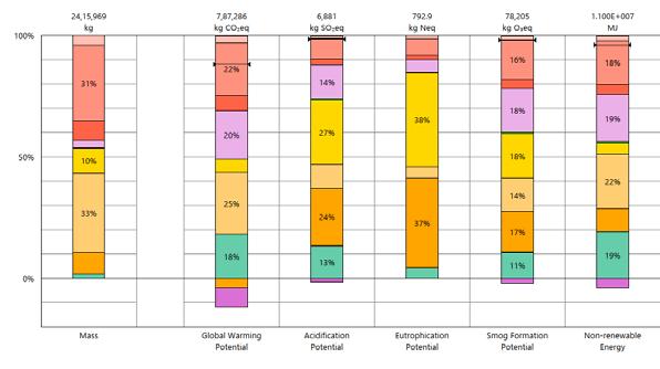
GLOBAL WARMING POTENTIAL
4300 170 160 700 100 100 VARIES (ALWAYS BELOW THE FROST LINE) 600 E.Q. E.Q. 3000 (CLEAR OPENING) ENCLOSURE SECTION 1
N.G.L.
KEY PLAN 2
KITCHENER ENCLOSURE DETAILS status 1:5 5/12/2023 UNIVERSITY OF WATERLOO CAMBRIDGE, O.N. CITY ALI Notes: REVISIONS: A WINDOW SIZE UPDATED AH 5/12/23 HASAN OF KITCHENER
ARCH671 A1
BUILDING ENVELOPE SECTION FOUNDATION DETAIL CARBON REPORT USING TALLY ARP


REVITALIZING LITTLE JAMAICA Urban Design and Housing Studio 02 27.5M 1.8M 1.8M 1.8M 3.3M 1.8M 1.6M 1.8M 24.0M 10.0M 3.3M 3.2M 3.2M 1.8M 3.0M 6.0M 1.0M 3.0M 6.0M 1.0M 10.0M 10.0M 15.0M 15.0M 1.6M VEHICULAR PARKING BIKE GREEN FRONTAGE WALK GREEN FRONTAGE WALK BIKE FLEX ZONE


WHAT NOW? TIMELINE ?
1. Diverse Communities
Mid Rise mixed use development along with community spaces to increase density and potential footfall.
2. Revitalize Old structures
Renovating and beautification of existing storefront bussiness or rehablitation of these into newer development.
3. Community loops
Converting in-active threshold spaces into active streets and spill over for assosiated uses.
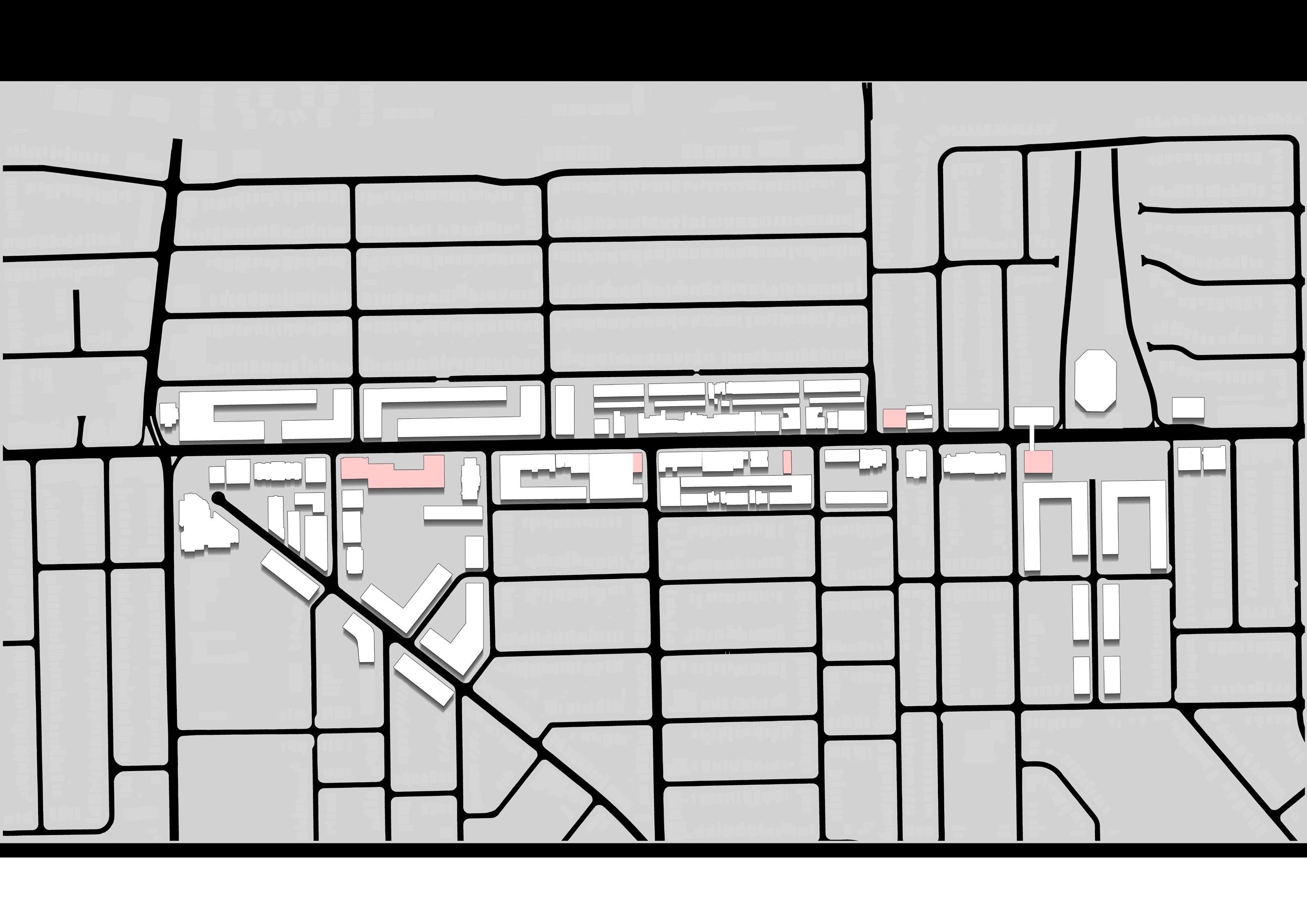
STRATERGY PLAN
The vision of the urban design exercise was to revitalise the urban spaces while preserving the spirit of Little Jamaica. To achieve this, important landmarks have been protected and surroundings are densified.
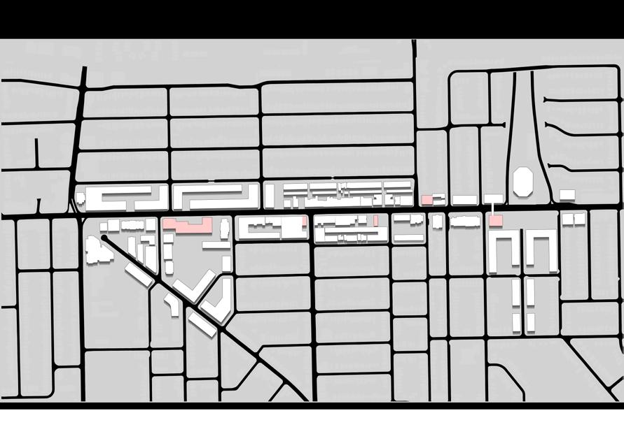
T T T * * * * * * * * * * EGLINGTON AVE MAJOR VEHICULAR ROUTES
T * * * * T * EGLINGTON AVE MAJOR VEHICULAR ROUTES PEDESTRIAN CONNECTION PEDESTRIAN ROUTES ACTIVE STREETWALL EDGE STREETWALL EDGE LRT STATIONS PROGRAMMING OPPORTUNITIES ACTIVATED PLAZA CONNECTION TO RAVINES & PARKS CULTURAL/ HIGH FOOTFALL PROGRAMS
Little Jamaica Retail
Footall Generator (like - Gym)
Connection to the Beltway Trails
Connection to the Ravine System
Connection to the community Parks & Pool
Mid-Rise Courtyard blocks
Community Courtyard
Affordable Housing on Station Land
Police station renovated to Exposition Center + Police station
Elevations


Resturant with outdoor seating
Laneway Houses

Barber shop with social canopy
Record store with open shop front

Elevations

Grocery store with outdoor display
Rap’s
Trejah
Adding on top of exisiting retail to densify and create public space
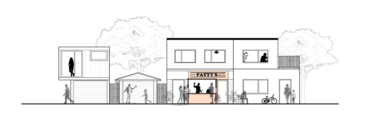
ADDING TO THE EXISTING

Laneway Houses
Converting garages to laneway housing and Affordable laneway retail
Reggae Lane emerges as a magnetic force, drawing crowds from Eglton Avenue into a lively retail street and plaza pulsating with music, cultural activities, and community engagement. Backlanes serve as vital pathways, guiding pedestrians to more secret pockets of community spaces
The hospital has been designed considering fast and easy circulation. Light, Ventilation have been optimized with a fully functional Emergency + OPD + Rehabilitative spaces. This monolithic building’s uniform, translucent glass rain screen veils the interior spaces. The cavity in the built form provides thermal control and light diffusion. Inside, an independent concrete structure positions double height reception above which is the rehabilitation space with its open corridor.
Arch Sem 3 | Individual | New Delhi, India | 2019
B.
Typical Block Extruded courtyard Sense of arrival Chamfer to connect 1. SELECTED TYPICAL GROUND COVERAGE FOR PROGRAM 2. EXTRUDED COURTYARD FOR MAXIMUM DAYLIGHT 5. MULTIPLE CORES FOR SPECIFIC FUNCTIONS 3. MOVED TO CREATE SENSE OF ARRIVAL 6.ROOFTOP REHAB FACILITIES 4. CHAMFERED TO CONNECT IPD EMERGENCY SERVICES 1. SELECTED TYPICAL GROUND COVERAGE FOR PROGRAM 2. EXTRUDED COURTYARD FOR MAXIMUM DAYLIGHT 5. MULTIPLE CORES FOR SPECIFIC FUNCTIONS 3. MOVED TO CREATE SENSE OF ARRIVAL 6.ROOFTOP REHAB FACILITIES 4. CHAMFERED TO CONNECT IPD EMERGENCY SERVICES 1. SELECTED TYPICAL GROUND COVERAGE FOR PROGRAM 2. EXTRUDED COURTYARD FOR MAXIMUM DAYLIGHT 5. MULTIPLE CORES FOR SPECIFIC FUNCTIONS 3. MOVED TO CREATE SENSE OF ARRIVAL 6.ROOFTOP REHAB FACILITIES 4. CHAMFERED TO CONNECT IPD EMERGENCY SERVICES 1. SELECTED TYPICAL GROUND COVERAGE FOR PROGRAM 2. EXTRUDED COURTYARD FOR MAXIMUM DAYLIGHT 5. MULTIPLE CORES FOR SPECIFIC FUNCTIONS 4. CHAMFERED TO CONNECT IPD EMERGENCY SERVICES
VALE ORTHOPEDIC HOSPITAL 03
THE

REVEAL
A Courtyard provides daylighting and promotes healing. It also acts as a spillover space to reduce over crowding and congestion.


Service Core


IPD Department

IPD Core

Service Floor over O.T.

Rehab @ Roof

Radiology

ACCESS FOR STAFF AND SERVICES
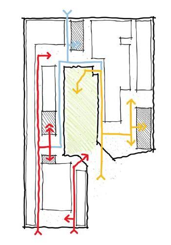
ACCESS TO RECEPTION

IPD + OPD Reception

Service Area

Emergency
ACCESS TO EMERGENCY


CIRCULATION TO USE BASKING IN THE SUN
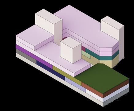
ZONING DIAGRAM
AXONOMETRIC DIAGRAM
The section emphasizes the various layers of programs inside a hospital, these were first extensively researched as part of the studio to understand the relationship between various functions.
LEGEND
IN- PATIENT DEPARTMENT
CORE
OPERATION THEATER
INTENSE CARE UNIT
OUT PATIENT DEPARTMENT
EMERGENCY
RADIOLOGY
MORTUARY
DOCTORS LOUNGE
CSSD


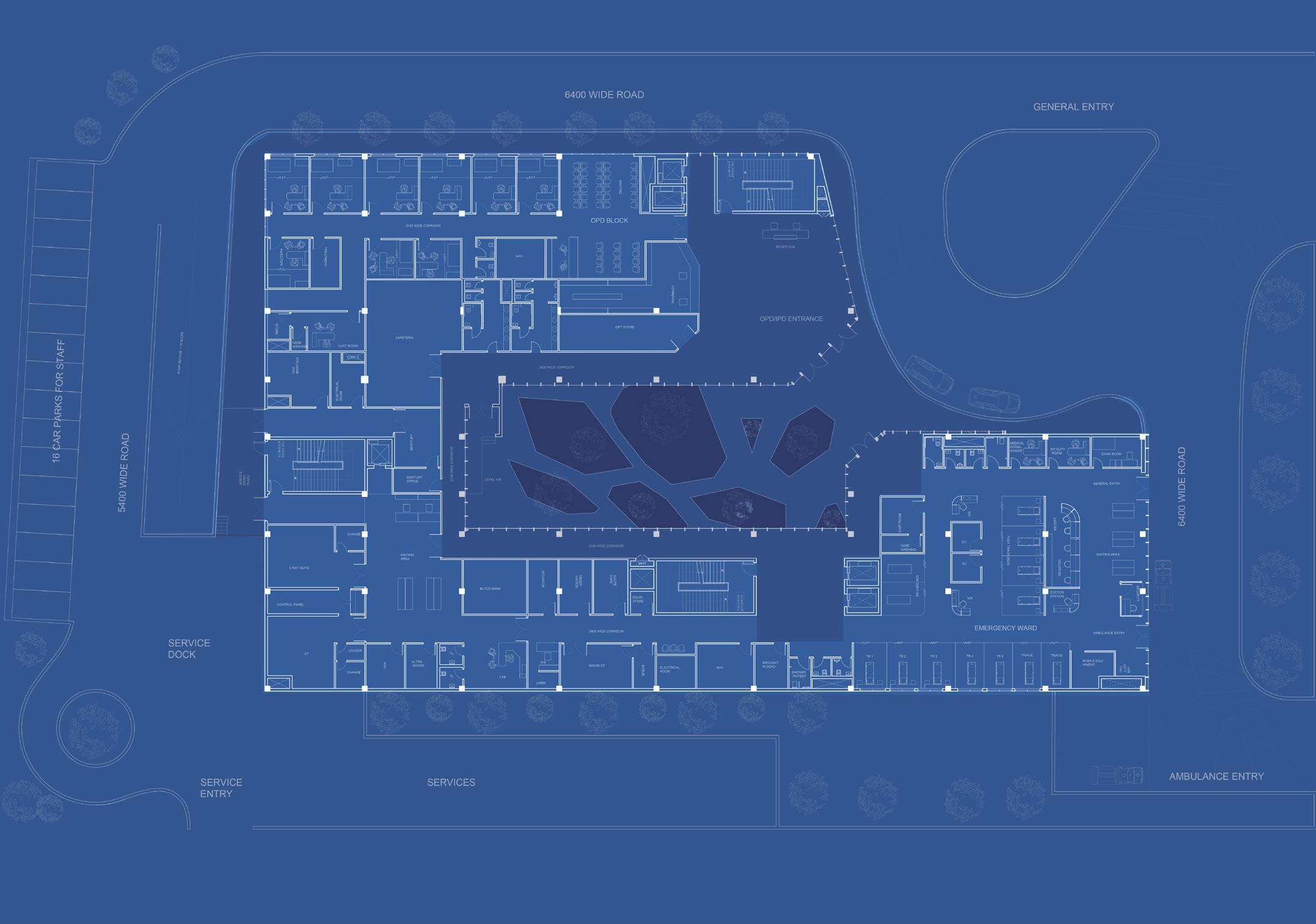
GROUND FLOOR LAYOUT
The plan is organized to allow for an easy access between departments. It is based on the multi-pronged layout which would allow for expansion of the hospital.


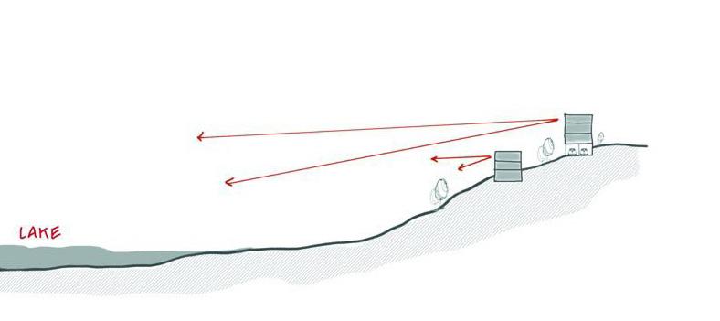
The Site was looked as left over from the passive reaction to the steep topography in an otherwise flat landscape. The value of the land is defined by its function as a housing society, but the project is envisioned as a large recreational green space. Where the design was based on an interest to activate the land through responding to the beautiful views of the lake as well as amplifying meeting place all around the site.


B. Arch. Housing Studio | Individual | Bhopal, India | 2019
looking clusters Projections facing lake INVERTED HOUSING OVERLOOKING LAKE 04
to topography
Outwards
Responding


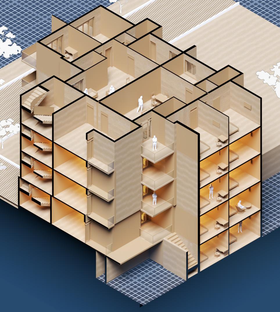


PHYSICAL MODEL
With the use of CNC machine, this model was build to experiment with strategic placement of building blocks on contours and create community spaces.
Cafe
Badminton
Tot- Lot Central Green + Club
Relax Sky-walk Picnic Pool
O.A.T 1 BHK EWS
3 BHK 2 BHK
3 BHK
SLOPE
To manage slopes, duplexes and basements are created along the slope lines.
VIEWS
Balcony is given along possible view lines to provide unhindered access to the view of the Lake from all rooms.
LIGHT & VENTILATION
Large openings provide light while external curtain system prevents exposure from sun. This also allows for ventilation of Hot air from inside through stack effect.
LEGEND
1. Green Roof Assembly
2. External Curtain
3. Louver Assembly
4. Community space at Stilt
5. Screen for Basement
Common Area

Duplex style layout
View to the Lake for all rooms
TOWNHOUSE LAYOUT
Common Area Courtyard

View to the Lake
3 BED ROOM DWELLING UNITS
SKIN SECTION
The design utilized contour to create dwelling units, all with natural light and ventilation and some which are spread over multiple floor allowing for an easy spill over onto the gardens at the lower level.
Walk-in Closet
Toilet & Bath
Separate
1
VIEW OF THE FOREST RESERVE




RESPONDING TO THE SITE
The houses are arranged to maximize potential sight-lines while responding to the contours to create interesting spaces. Allowing for sight-lines from kitchen balconies overlooking children playing in the courtyards.
SERVICE SPACE EWS PARK FACING CLUB HOUSE 1 BHK SKY WALK CONNECTION CENTRAL GREEN SPACE TO LAKE FACING GREENS
Joint Household Extended Household Nuclear Household Shared Household TOTAL 340 UNITS
LINEAR SETTLEMENT

BOBBIN’
Winter Station U.W. Team
Competition Winner | Group | Toronto, Canada | 2024
Bobbin’ is a design build project which is aimed to invite the visitors to a place where pivotal moments and whimsical memories prompt reflection. It shelters visitors with slats that create an ever-changing threshold between the bobbing zone and the surrounding beach. The seesaws draw from the playground-like Sling Swing and Lifeline projects, while its form within the landscape reflects HotBox and Introspection. Each material has been sourced from previous student projects in addition to salvaged materials from the community of Cambridge. As you navigate through, bobbing up and down, a fresh perspective unfolds, encouraging resonance with the surrounding and past Winter Stations.
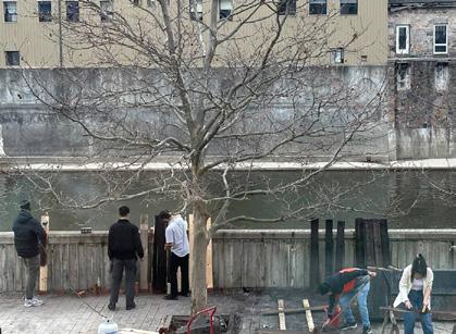


 TEAM WORK
CLEANING
BLOW TORCHING
TEAM WORK
TEAM WORK
CLEANING
BLOW TORCHING
TEAM WORK
05

This residence was designed for Dr, Jameel, it was a very rewarding experience for me. Design process as well as site interactions helped me in learning architectural design in a more comprehensive manner. The residence was a multistory dwelling designed to be inhabited by the extended family of the client, at one floor. The rest were to be either rented or sold. This required thinking about privacy and conversations with the client about their desired lifestyle.
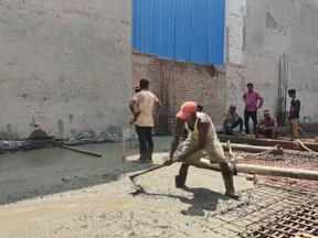

laying Slab pouring Personal project | Individual | New Delhi, India | 2022 RESIDENCE Freelance design and Site supervision 06
Beam


WORKING DRAWINGS
The challenging aspect of the project was delivering drawings which would allow all the involved stakeholders to complete the project without any problems. This required meticulous display of required measurements on the drawings.
DATA CENTER PROJECTS
BIM Modeling and Co-ordination
Architectural Internship | Team Work | Gurugram, India | 2023
I played a crucial role in the final stages of building development, focusing on refining construction drawings for GFC and Tendering stages. Collaborating closely with engineers, I ensured coherence and compliance of the building Information Model (BIM), facilitating interdisciplinary coordination. Additionally, I engaged with international Aecom Design teams, contributing to knowledge sharing between the U.K. and India offices, including involvement in the proposal stage of another project. Below, you’ll find the BIM models and drawings produced for this endeavor.


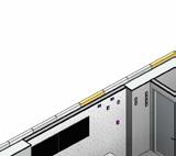




G.F.C LEVEL BIM DRAWINGS SOC OFC 1.01.A.09 2700 SP1-1 Carpet Tile 30.00mm 2700 ACT (F-14) (F-29) (F-11) (F-5) E-43 1 3 L01 PLINTH FFL 101250.00 2 3300 2350 4000 ACT Carpet Tile 30.00mm SOC 1.01.A.08 3970 1680 1350 (F-49) (F-11) E-33 TEL (F-11) (F-49) E-50 (B-DRAW) GLASS AS PER SPECS PASSTHROUGH DRAWERS WITHIN FIXED DETAILS (B-DRAW) SP1-1 SW1 GLZ-3 1 3 L01 PLINTH FFL 101250.00 2 3300 2350 ACT 4000 1680 SECURE LOBBY 1.01.A.02 Concrete Sealer 30.00mm DEAL DRAWERS (F-49) (F-49) SW1 GLZ-3 SP1-1 1260 1800 910 GLASS AS PER SPECS SECURE GUARD PASSTHROUGH DRAWERS WITHIN FIXED JOINERY. REFER TO DETAILS CIR ENROLLMENT READER CIR ENROLLMENT READER 1 3 4 L01 PLINTH FFL 101250.00 2 Carpet Tile 30.00mm SP1-1 SP1-1 ACT 2700 SOC OFC 1.01.A.09 SOC STORE 1.01.A.10 3300 2350 2290 (F-14) E-11 (F-22) (F-5) (F-30) (F-31) (F-31) 330 2680 2670 (F-11) (WB) Carpet Tile 30.00mm 2110 1850 600 762 1680 CARD READER ACT 4000 Concrete Sealer 30.00mm 3970 FORCED ENTRY/IMPACT RESISTANT WALL IMPACT RESISTANT GLASS AS PER SPECS (F-49) (F-11) 1 3 4 L01 PLINTH FFL 101250.00 2 SOC 1.01.A.08 1.01.A.08A 4000 ACT (COAT HANGER) (F-49) (F-29) (F-49) 914.5 1340 RESPONDER AO (PRIV-SC-01) 4000 1680 1 3 4 2 SOC 1.01.A.08 SP1-1 SP1-1 1.01.A.09 1.01.A.10 2 J-004-0 AED FIRST AID BOX (F-19) (F-20) ACT MICROSOFT LOGO LOCATION FOR MICROSOFT LOGO DIRECT FIXED TO WALL 'AED' WALL MOUNTED AUTOMATED EXTERNAL DEFIBRILLATOR GLZ-5 FLUSHED WITH WALL 4000 N DRAWING STATUS CLIENT OWNER PRINCIPAL CONSULTANT PROJECT DRAWING TITLE DWG NO. DRAWN BY DESIGNED BY CHECKED BY APPROVED BY DATE OF FIRST ISSUE REV. PROJECT NO. HYD01 HYDERABAD DATA CENTER SCALE A1 NOTES: 9th Floor, Infinity Tower- 'C', DLF Cybercity, DLF Phase Gurugram, 122002 +91 124 4830100, 91 124 4830108 Web:- www.aecom.com AECOM ©AECOM Asia Company Ltd. 2020 The information contained this document produced AECOM solely use the Client identified the cover sheet the purpose for which has been prepared and AECOM undertakes no duty accepts any responsibility any third party who ma rely upon this document. rights reserved. No section element document may removed from this document, reproduced, electronically stored transmitted any form without the written permissio AECOM. KEY PLAN P.17983 ©2021 AECOM Corporation PROTECTIVE SECURITY CONSULTANT 300 Beach Road #23-00 The Concourse Singapore 199555 +65 6299 2466, +65 6299 0297 Web:- www.aecom.com AECOM Singapore Pte Ltd EPCM CONTRACTOR 6th Floor, Infinity Tower B, DLF Cybercity, DLF Phase Gurugram, Haryana, India 122002 www.fluor.com Fluor Daniel India Private Limited AECOM PROJECT NO. 60683502 As indicated HYD01-A-L-120-A PG JB JB AC ISSUED FOR CONSTRUCTION (IFC) 25-Nov-2022 SOC DETAIL SHEET 2 1 50 ELEVATION - F ( SOC ) 5 1 : 50 ELEVATION - G ( SOC ) 1 1 50 ELEVATION - I ( SOC ) 7 REV DATE DESCRIPTION 25-NOV-2022 ISSUED FOR CONSTRUCTION (IFC)
50 ELEVATION - E ( SOC ) 3 1 50 ELEVATION - H ( SOC ) 6 ELECTRICAL AND HARDWARE NOTES: 1. DOOR HARDWARE COMPONENTS SUCH AS KEYS, SEALS, CLOSURES, COORDINATORS, AUTOMATIC OPENERS AND OTHER MATERIALS USED IN THE CONSTRUCTION OF THE DOOR MUST BE INSTALLED AND IN GOOD WORKING ORDER PRIOR TO INSTALLATION OF SECURITY DEVICES. 2. ELECTRONIC DOOR HARDWARE COMPONENTS, SUCH AS ELECTRIFIED LOCKS, ELECTRIC TRANSFER HINGES AND LOCAL HIGH AMP IN-RUSH POWER SUPPLIES ARE TO BE PROVIDED AND INSTALLED BY DOOR HARDWARE CONTRACTOR. TERMINATIONS BY SPECIALTY LOW VOLTAGE CONTRACTOR EXCEPT WHERE PRE-MADE IN FACTORY. 3. ELECTRICAL COMPONENTS SUCH AS BOXES, COVERS, RINGS, COUPLERS, HANGERS, STRUTS, CONDUITS, CABLE WIREWAYS/TRUNKING, POLES, POLE BASES AND OTHER MATERIALS USED IN THE CABLE RACEWAY SYSTEM SHALL BE PROVIDED ND INSTALLED BY ELECTRICAL CONTRACTOR UNLESS OTHERWISE NOTED. SECURITY NOTES: 1. SECURITY EQUIPMENT PROVIDED AND INSTALLED BY THE SECURITY CONTRACTOR UNLESS OTHERWISE NOTED. 2. CONTACT THE SECURITY DESIGNER IF ANY EQUIPMENT CANNOT BE MOUNTED WITHIN THE DISTANCES AND TOLERANCES SPECIFIED. 3. TERMINATE SHIELDED DRAIN WIRES AT THE PANEL SIDE ONLY. 4. USE END OF LINE (EOL) SUPERVISION RESISTORS AT ALL DOOR CONTACTS, REQUEST TO EXITS, ALARM DEVICES, AND OTHER MONITORED POINTS. 5. MINIMIZE ALL SPLICES IN CABLES, BUT WHERE REQUIRED USE NYLON CRIMP CONNECTORS AND PROTECT SPLICE WITH PROTECTIVE SHRINK TUBE COVER. 6. FOR SURFACE MOUNTED CONTACTS, AN ARMORED CABLE IS ACCEPTABLE UP TO 460mm BEFORE CONNECTING TO AN ELECTRICAL BOX. SPECIAL NOTE: 1. SECURITY CONTRACTOR TO ENSURE TWO "DEAL DRAWERS" ARE INSTALLED AND CENTERED ON THE WALL BETWEEN SOC AND LOBBY. 2. EACH DEAL DRAWER SHALL MEASURE 18 in. (86 cm) WIDE X 5 n. (13 cm) HEIGHT X 25 in. (64 cm) LENGTH AND HAVE A DOUBLE-HINGED LID. 3. THE DEAL DRAWER SHALL BE INSTALLED AT 30 in. (86 cm) ABOVE FINISHED FLOOR AND DESKTOP SURFACES ADJOINING THE "DEAL DRAWER" ON EITHER SIDE WILL BE INSTALLED FLUSH WITH HIS HEIGHT. 4. SECURITY CONTRACTOR TO ENSURE BADGE STORAGE DRAWERS (TYPICALLY TWO) BE PROVISIONED WITH CUSTOM INSERTS TO ACCOMMODATE UPRIGHT TEMPORARY BADGE STORAGE PROXIMATE TO THE DEAL DRAWER. 5. EACH BADGE STORAGE DRAWER SHALL BE BUILT WITH 150 SLOTS (TYPICALLY 5 ROWS, 30 SLOTS EACH) ANGLED BACKWARD 10 DEGREES, AND PROPERLY SIZED TO ACCOMMODATE THE BADGE BEING USED. TYPICAL BADGE SIZE IS 2-1/8 n. W x 3-3/8 in. H 1/32 in. D. 6. SECURITY CONTRACTOR TO ENSURE KEY MANAGEMENT SYSTEM BE ROVISIONED ACCORDING TO PROJECT REQUIREMENT. 7. SECURITY CONTRACTOR TO ENSURE CRS WORKSTATION BE PROVISIONED WITH MONITOR MOUNT CAPABLE OF HOLDING SIX (6) MONITORS IN A 3-OVER-3 CONFIGURATION. 8. SECURITY CONTRACTOR TO ENSURE CRS WORKSTATION AND DCAT WORKSTATION BE PROVISIONED WITH USB READER. 9. SECURITY CONTRACTOR TO ENSURE SOC DURESS BUTTONS ARE WITHIN EASY AND INCONSPICUOUS REACH WHILE SEATED (RIGHT SIDE WHEN SEATED). 10. SECURITY CONTRACTOR TO ENSURE PROVISION OF TWO UNITS OF SOC REMOTE RELEASE READERS AT CRS WORKSTATION. A CARD READER THAT CONTROLS THE ADMIN ENTRY (EXIT ONLY) DOOR (FURTHEST FROM THE SOC) SHALL BE LOCATED UNDER THE CRS WORKSTATION DESK (RIGHT SIDE WHEN SEATED). A CARD READER THAT CONTROLS THE INTERIOR SET OF VESTIBULE DOORS SHALL BE LOCATED UNDER THE CRS WORKSTATION DESK (LEFT SIDE WHEN SEATED). NOTE1. WINDOWS AND WALLS THAT ARE GLZ2-2 GLZ2-3 BETWEEN THE LOBBY AND THE SOC (SECURITY OFFICE), WILL UTILIZE FORCED ENTRY RATED MATERIALS. 2. REFER HYD01-E-P-109-A FOR POWER POINTS 3. REFER HYD01-T-D-102 FOR DATA POINTS NOTEALL FIXTURES TO BE ADDED IN COMPLIANCE WITH SECURITY REQUIREMENT THE LOCATION OF HANGERS SHOULD BE COORDINATED WITH PT SLAB TENDONS. 1 50 ELEVATION - C ( SOC ) 4 1 50 ELEVATION - D ( SOC ) 2 3D - SOC 8 07
1

FACADE OPTION 1: RENDERING
Adding complimentary colors to the Data Center building making it lively, this was amongst multiple proposed options as part of the design scheme.






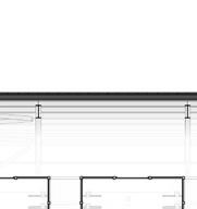
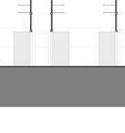


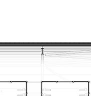
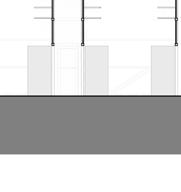


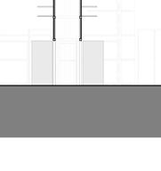


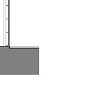

TRANSVERSE SECTION OF OFFICE


FLOOR PLAN OF AXILLARY GIS BUILDING BUILDING SECTION OF AXILLARY GIS BUILDING
G.F.C BIM MODEL
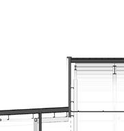
Delivering drawing and model which can would smoothly guide construction on site, Required co-ordination with various disciplines as well as the U.K. Office. I was involved in clash detection and creating the co-ordinated drawing set.
Level 0G 0 A C E B D FSA Level 01 4500 DH Roof Level 9385 DH Level 01 7000 B1 C1 D1 E1 F1 G1 H1 I1 J1 K1 L1 A1 4000 4000 4000 4000 2500 6000 6000 6000 6000 6000 6000 6000 6000 6000 2500 59000 19 m² Entrance/Vestibule 0A101 21 m² Entrance Lobby 0A100 46 m² Disk Erase Processing 0A205 42 m² BUZ 0A140 Insulated Signle Ply Roof System Gypsum lining system Internal composite panel partition Internal composite panel partition Aluminium standing seam profiled sheet built up roof system on steel deck over purlins Structural grid ceiling system Main Passenger Entrance External Canopy 16000 0A110B 0A204C 3 1200 Entrance Curtain Wall 3200 Panel Height 8920 9002 5438 1413 m² Data Hall 0A500 59830 mm - DCH 16733 mm - FSA -150 5747 4767 1 19 -150 5400 5400 5400 5400 5400 5400 5400 Typical 5400 5400 Typical 1500 Typical 1868 Level 0G 0 1 2 4 3 6 7 8 5 9 FSA Level 01 4500 DH Roof Level 9385 DH Level 01 7000 02 01 10 11 12 4000 4000 4000 4000 4000 4000 4000 4000 4000 4000 4000 44000 84 m² Loading Dock 0A200 24 m² FOH/BOH Control & Security 0A111 19 m² Entrance/Vestibule 0A101 m² Toilet/Shower 01 0A104 23 m² Network Operation Centre 0A136 23 m² Security Operation Centre 0A135 23 m² Conference Incident Room 0A134 0A203A 0A203B 0A208A 0A111A 0A106A 0A136A 0A134A Main Passenger Entrance External Canopy Typical 1000 1 6 9 48732 mm FSA 2 Typical 8000 5665 Aluminium standing seam profiled sheet built up roof system on steel deck over purlins Insulated Signle Ply Roof System TX Enclosure 23000 MV Rooms 9465 -1200 4200 1 6 9 13 10 m² Vestibule 0A209 74 m² FSA Office 0A102 1:19 3° 0A135A 0A102B 0A102A Level 0G FSA Level 01 4500 DH Roof Level 9385 DH Level 01 7000 02 01 19 m² Electrical Switchroom 0A307 14 m² TX Enclosure 0A302 23000 11574 mm Mechanical Yard Generator IAC 1 6 9 Clear 2500 Typical 17300 4163 9384 5438 HACs 2631 14931 4838 5500 3800 23983 mm - DCH 2592 Typical 5920 2612 9 1:6 -150 -150 Space allowance for plenumsubject to CFD study. 2374 7458 Structural grid ceiling system Typical 5500 Fuel Tank Drawing notes: Drawings to be read in colour and in scale. All dimensions are in mm (millimetre) U.N.O. All levels are and in m (meter) U.N.O. No dimensions are to be scaled off this drawing planning or QS purposes. in doubt ask BWT. Other relevant documents: Architectural: 1A-A-2001-0Ground Floor Plan (DCH, FSA, Yard) 1A-A-2100-0 Fire Strategy Plan -Ground Floor (DCH, FSA, Yard) 1A-A-2102-0Security Diagrams -Ground Floor (DCH, FSA, Yard) 1A-A-2104-0Outline Scoping Plan -Ground Floor (DCH, FSA, Yard) 1A-A-2106-0Access and Maintenance -Ground (DCH, FSA, Yard) 1A-A-2200-RRoof Plan 1A-A-3000-ZNorth and South Elevations 1A-A-3001-ZEast and West Elevations 1A-A-3300-ZTransverse and Longitudinal Sections Structural drawings MEP drawings Civils drawings Legend: General Dimensions xxx Note: The FSA displayed in this drawing represents Option. For extended versions, refer to the 1 100 Longitudinal Section -FSA & DCH 1 1 100 Transverse Section -FSA 2 1 100 Transverse Section -DCH 3 DN UP UP DN DN DN UP UP DN DN 2 I-001-0 H-001-0 3 CABLE CELLAR STAIR 2 H-001-0 2 3 I-001-0 STAIR 1 D2 D2 D2 900 3000 106.850 106.850 3300 1 L-001-0 D4 2000 2000 900 H-001-0 4 106.850 F-31 F-32 F-32 F-32 F-31 F-25 F-31 F-31 F-25 STORE ROOM 8930 D2 W3 PL SHAFT 3780 106.850 1500 8700 8900 500 2530 GS2 GS1 GS3 GS4 GS5 GSA GSB GSC 11660 6750 9750 3750 31910 2700 12250 22110 3500 3600 22110 D2 Room Legend CABLE CELLAR PL SHAFT STAIR 1 STAIR 2 STORE ROOM I-001-0 2 I-001-0 H-001-0 1 H-001-0 3 4 I-001-0 H-001-0 2 OPENABLE RAILING D1 D1 D1 D1 D1 D1 D1 D1 3 I-001-0 RS1 D1 4860 D2 D2 D1 3600 110.400 110.350 110.410 110.400 EYE WASH PROJECTION AS/ STR. 3300 1500 8700 D3 7 L-201-0 2 L-001-0 9 L-001-0 W1 W1 W1 W1 W1 W1 W1 W1 W1 W1 W1 W1 W1 W2 W1 W1 2580 500 3760 1500 F-32 F-32 F-32 9840 3000 11850 H-001-0 4 1500 2430 F-30 F-12 F-30 F-12 F-12 CONTROL ROOM BATTERY ROOM 1200 760 11610 LV SWITCHGEAR ROOM MEETING ROOM/ OFFICE F-38 F-38 F-38 F-38 F-38 F-38 F-41 F-41 110.400 F-12 F-12 F-12 880 780 4050 220kV AIS CONTROL ROOM CORRIDOR 2500 TOILET 3220 CORRDIOR 1500 110.350 110.497 1 L-201-0 110.400 110.350 GS2 GS1 GS3 GS4 GS5 GSA GSB GSC GSD 7160 2700 12250 22110 11660 6750 9750 3750 31910 7860 3300 7060 6300 7060 7060 10080 2520 12130 16590 9120 2800 METERING ROOM 21660 STAIR 2 GIS ROOM STAIR 1 SLOPE 1:100 550 700 870 2550 1180 2640 2820 1200 2060 800 2370 1880 1040 2050 3470 3330 2770 3970 2260 PROJECTION AS/ STR. PROJECTION AS/ STR. PROJECTION AS/ STR. Room Legend 220kV AIS CONTROL ROOM BATTERY ROOM CONTROL ROOM CORRDIOR CORRIDOR GIS ROOM LV SWITCHGEAR ROOM MEETING ROOM/ OFFICE METERING ROOM PL SHAFT STAIR 1 STAIR 2 TOILET 2 I-001-0 H-001-0 3 H-001-0 2 3 I-001-0 3 L-001-0 3300 1500 1500 1500 115.500 3500 H-001-0 4 1830 D2 W1 W1 D2 115.416 115.390 GS2 GS1 GS3 GS4 GS5 GSA GSB GSC 2700 12250 22110 11660 6750 9750 3750 31910 GIS ROOM STAIR 2 16590 12130 8700 SLOPE 8900 13210 16820 12340 SLOPE 1:100 SLOPE 1:100 Room Legend GIS ROOM STAIR 1 STAIR 2 1 I-001-0 2 I-001-0 H-001-0 1 H-001-0 3 4 I-001-0 H-001-0 2 3 I-001-0 SLOPE1:100 SLOPE1:100 SLOPE 1:100 123.400 3600 12330 9780 H-001-0 4 SLOPE 1:100 28060 119.150 119.150 115.419 GS2 GS1 GS3 GS4 GS5 GSA GSB GSC GSD 11660 6750 9750 3750 31910 7160 2700 12250 22110 22110 3600 16620 7740 3400 12130 12130 SLOPE 1:100 SLOPE 1:100 SLOPE 1:100 3700 DOG HOUSE (ELEC.) AS PER DETAIL DOG HOUSE (FIRE FIGHTING) AS PER DETAIL DOG HOUSE (FIRE FIGHTING) AS PER DETAIL DOG HOUSE (MECH.) AS PER DETAIL GIS FINISHES SCHEDULE ROOM NAME FINISHES FLOOR WALL CABLE CELLAR CONCRETE SEALER PAINT STAIR 2 CONCRETE SEALER PAINT STAIR 1 CONCRETE SEALER PAINT PL SHAFT CONCRETE SEALER PAINT STORE ROOM CONCRETE SEALER PAINT METERING ROOM CONCRETE SEALER PAINT CONTROL ROOM CONCRETE SEALER PAINT LV SWITCHGEAR ROOM CONCRETE SEALER PAINT TOILET TILES TILE 220kV AIS CONTROL ROOM CONCRETE SEALER PAINT CORRIDOR CONCRETE SEALER PAINT METERING ROOM CONCRETE SEALER PAINT MEETING ROOM/ OFFICE CONCRETE SEALER PAINT BATTERY ROOM CONCRETE SEALER PAINT CORRDIOR CONCRETE SEALER PAINT STAIR 1 CONCRETE SEALER PAINT 1 100 GIS L01 1 1 100 GIS L02 2 1 : 100 GIS L03 3 1 : 100 GIS L04 4 CONTROL ROOM 2.07 CABLE CELLAR 1.04 D1 D2 D2 7900 4900 3550 450 2520 16800 8000 CORRIDOR 2.06 PARAPET 1000MM HIGH PARAPET 1000 MM HIGH 1000MM HIGH PROJECTION AS/ STR. DOUBLE HEIGHT SPACE CRANE GIRDER AS/VENDOR 8800 4200 750 2600 12050 ACT 3050 3050 2200 CAGE LADDER FOR ROOF ACCESS AS/ SPECS. D2 D4 GIS ROOM 3.07 Room Legend CABLE CELLAR CONTROL ROOM CORRIDOR GIS ROOM GIS L01 106.800 FGL 106.350 GIS L02 110.350 GIS L03 115.250 GIS L04 123.150 D1 CABLE CELLAR 1.04 7900 4900 3550 450 16800 3450 8700 D1 D1 D1 TOILET 2.10 CORRIDOR 2.06 STAIR 2 1.02 MUMTY 1000MM HIGH PARAPET 1000MM HIGH PROJECTION AS/ STR. RAILING AS/ SPEC. RAILING AS/ SPEC. 2900 600 5150 2850 450 2400 950 4000 750 CORRDIOR 2.02 ACT 2750 2800 1950 2800 CAGE LADDER FOR ROOF ACCESS AS/ SPECS. DUCT AS/ MECH. Room Legend CABLE CELLAR CORRDIOR CORRIDOR PL SHAFT STAIR 2 TOILET 7900 4900 3550 450 16800 D1 D1 D1 D1 CABLE CELLAR 1.04 BATTERY ROOM 2.04 PARAPET 1000MM HIGH 8000 MUMTY PROJECTION OVER LOADING DOCK PROJECTION AS/ STR. RAILING AS/ SPEC. STAIR 1 STORE ROOM 3.03 DOUBLE HEIGHT SPACE CRANE GIRDER AS/VENDOR GS2 GS1 GS3 GS4 GS5 11660 6750 9750 3750 31910 450 2850 5150 1100 2400 600 2750 2800 CORRDIOR 2.02 750 3990 750 2600 8350 CAGE LADDER FOR ROOF ACCESS AS/ SPECS. 650 12000 GIS ROOM 3.07 Room Legend BATTERY ROOM CABLE CELLAR CORRDIOR GIS ROOM STAIR 1 STORE ROOM GIS L01 106.800 FGL 106.350 GIS L02 110.350 GIS L03 115.250 4900 3550 450 TOILET 2.10 CABLE CELLAR 1.04 220kV AIS CONTROL ROOM 2.09 METERING ROOM 2.11 D2 STAIR 1 8900 3450 5000 3700 5800 3980 2370 4770 2350 3690 1330 W1 W1 PROJECTION AS/ STR. PARAPET 1000MM HIGH PARAPET 600MM HIGH GSA GSB GSC GSD 12250 2700 7160 22110 750 2600 600 1120 3030 ACT 1 3050 ACT 2750 2800 1950 650 4100 DOG HOUSE (MECH.) AS PER DETAIL Room Legend 220kV AIS CONTROL CABLE CELLAR METERING ROOM STAIR 1 TOILET 1 : 100 Section - A (GIS) 1 1 : 100 Section - B (GIS) 2 1 : 100 Section - C (GIS) 3 1 : 100 Section - D (GIS) 4
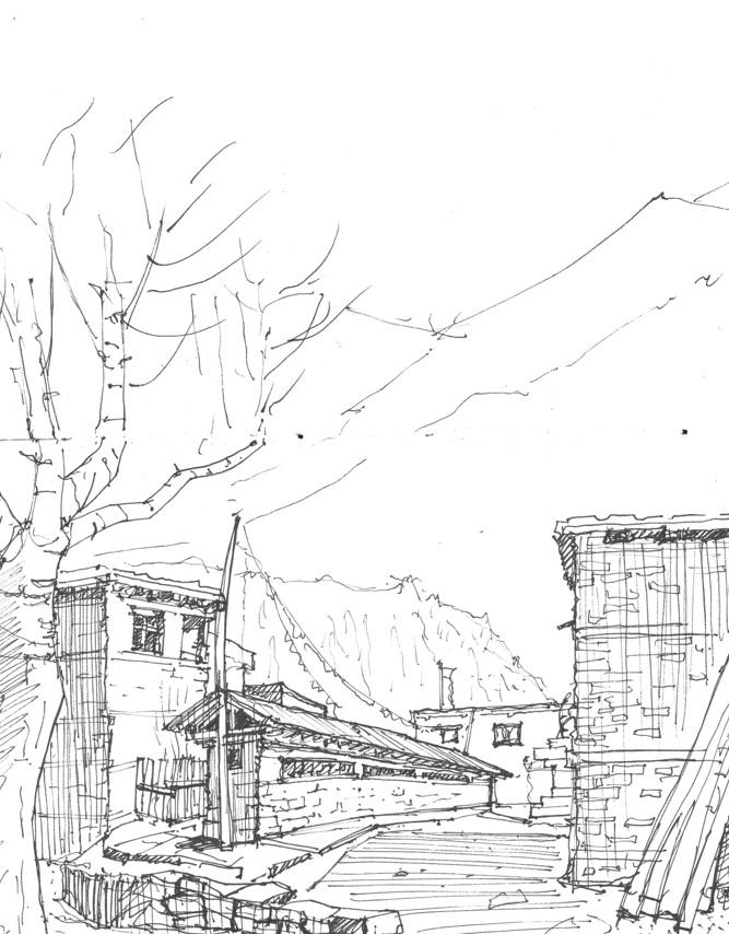
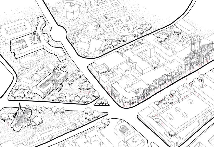
MISCELLANEOUS Field sketching + Heritage documentation 08



GENERATIVE DESIGN
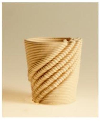
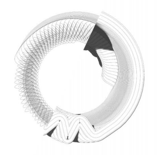
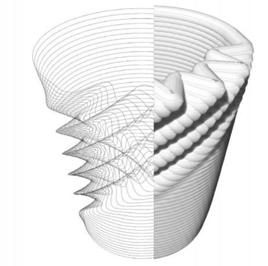
With the use of grasshopper scripts, I have attempted to explore new possibilites of materialization beyond predefined creation of forms.
Clay 3d printed using simple grasshopper scripts
Modelling a High rise tower with the use of generative design in grasshopper

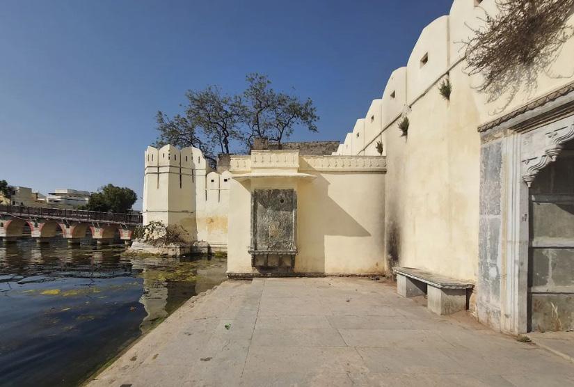
HERITAGE DOCUMENTATION
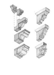


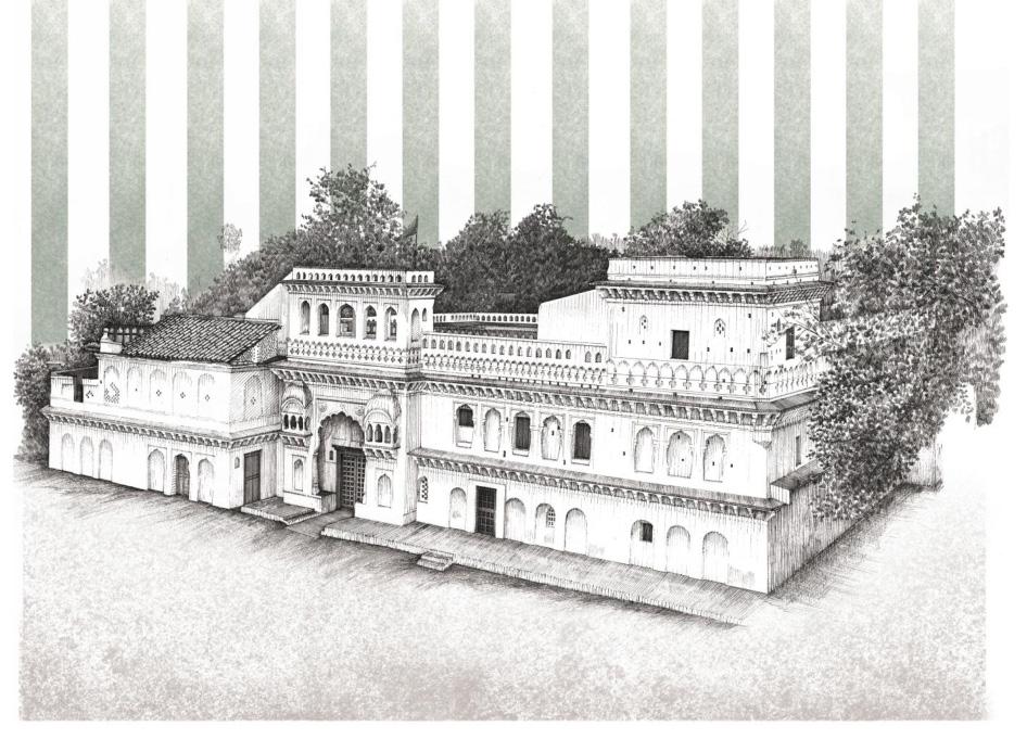
 Above are hand drafted documentation of Havellis of Udaipur. This was a collaborative effort involving extensive site visits and field sketching.
SELECTED WORK 2018 - 2024
a59hasan@uwaterloo.ca
+12262017336


 TEAM WORK
CLEANING
BLOW TORCHING
TEAM WORK
TEAM WORK
CLEANING
BLOW TORCHING
TEAM WORK


