12 minute read
Additive Manufacturing as a Problem-Solving Tool in Pharmaceutical Processing
A hybrid raxial mixing impeller is designed and implemented to resolve dispersion mixing issues in a pharmaceutical application
While process automation, a core tenet of the transition to Industry 4.0, can minimize or eliminate processing issues associated with a wide range of material variability, some variations require physical alterations to processing equipment to be implemented. In this article segregation issues caused by an API supplier-change are addressed rapidly and efficiently via another pillar of Industry 4.0, additive manufacturing.
Chris O’Callaghan*
Innopharma Technology Ltd.
Caroline McCormack
Innopharma Technology Ltd.
Sam Solomon
Department of Chemical Sciences and Bernal Institute, University of Limerick
Patrick Cronin
Department of Chemical Sciences and Bernal Institute, University of Limerick
Ian Jones
Innopharma College of Applied Sciences Ltd.
At the core of the transition to Industry 4.0 is the drive toward robust, reliable and comprehensive process automation. Three of the nine pillars of Industry 4.0 : Internet of Things, System Integration and Autonomous Robotics are particularly well suited to supporting this objective. With effective and democratised automation delivered by a range of available process digitalisation platforms, processing issues such as those caused by raw material variability from supplier or up-stream processing steps can often be addressed with no quality or time penalties.
Some raw material variations however require more intervention than pure automation tools can provide, instead requiring physical re-configuration of process equipment. In this application another pillar of Industry 4.0, additive manufacturing, can be employed to address certain physical/ equipment issues in shorter timeframes than otherwise possible, ensuring quality is optimally maintained and production schedules can continue to be met.
In this article, a processing issue is discussed in which a change in the supply of Propranolol HCL API resulted in significant challenges coating this API onto substrate pellets in an established Wurster Coating process. When analysed the new-supplier API was found to have a multimodal particle size distribution, as compared to the broadly Gaussian distribution of the original API. This multimodality resulted in significant settling of the coating dispersion even while actively stirred throughout processing. Process and control constraints limited how aggressively this dispersion could be stirred and how much stirrer clearance could be used, ultimately requiring a change to the mixing impeller used.
“Standard” axial and radial impeller types were both trialed but solids separation issues were identified for each in their respectively weaker mixing areas. Ultimately a hybrid radialaxial or “raxial” impeller was designed and rapid-prototyped via FDM printing. This impeller was determined to resolve the separation issues identified as well as significantly improve impeller performance against secondary design objectives, allowing for further optimisation of the real-time process automation.
Identifying the issue
The author’s company operates a process application and contract research laboratory in Dublin, Ireland. This lab provides a wide range of non-GMP development-scale pharmaceutical processing operations including crystallisation, fluid bed (drying, granulation and coating), twin-screw granulation / extrusion, and compression. A suite of accompanying analytical instruments is also available. As part of ongoing partner-research on advanced control of fluid bed Wurster coating, a series of experiments were to be conducted involving the API coating and subsequent functional coating of a variety of sizes of sucrose pellet cores.
Since previous experimental campaigns, a fresh supply of API (Propranolol HCL) had been sourced from a new supplier (Supplier B), meeting an equivalent material specification to that which had been used previously. All other materials and mixing parameters remained unchanged. The impeller used was an axial design.
In executing the first of these API-layering batches a similar automated process control strategy was followed to that which had been used in previous experimental campaigns. The process scientist monitoring the batch noted however that a significant sludgy deposit remained
around the outer edge of the coating dispersion beaker base when the API & binder dispersion had been fully sprayed. In the execution of a subsequent batch, the contents of the dispersion beaker were carefully monitored with solids settling noted despite an increase in stirrer RPM. Assay results for these batches confirmed API concentrations below 80% indicating significant losses. On a subsequent batch, a radial-design impeller was trialed with some improvement, however deposits still remained on the bottom of the beaker.
Analysis of API materials
To investigate the root cause of the observed solids sedimentation, a sample from each API batch (Supplier A and Supplier B) was analysed for particle size distribution (PSD) and morphology at the University of Limerick.
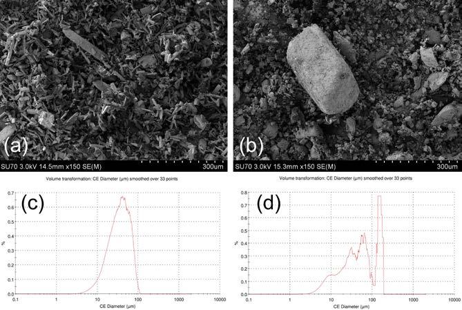
A visual examination was first conducted by Scanning Electron Microscopy (SEM) at multiple magnifications. The results confirmed differences in the physical characteristics / morphological features of both API samples. API from Supplier A was found to be more needle-like in appearance Figure 1a, while the API from Supplier B appeared more cubic in shape Figure 1b, indicating the two samples are likely different polymorphic forms.
PSD analysis was conducted on both samples using Malvern’s Morpholgi G3 particle characterisation instrument. Significant differences were again observed for both API samples. The volume distribution from Supplier A Figure 1c produced a typical Gaussian curve while Supplier BFigure 1d produced a multi-modal distribution curve with a larger maximum particle size.
These differences in particle size, distribution and shape morphology between the API batches would contribute to differences in mixing behaviors observed for the two API coating dispersions under similar mixing conditions. The difficulties experienced maintaining the API from Supplier B in suspension are therefore likely due to the greater percentage of larger particles present, represented by the visible right-hand spike in CE diameter values.
Stirring Constraints and Secondary Optimisation Objectives
In an initial attempt to resolve the observed settling issue the axial impeller previously used was swapped for a radial impeller which altered the location of observed deposits, but was similarly unable to effectively homogenize the dispersion without the use of excessive mixing speed. Several additional constraints existed on the process in question beyond the core need to effectively homogenize the dispersion, exacerbating the mixing challenges. • Any impeller design used had to be installed with minimal clearance to the bottom of the dispersion beaker, approximately 5 - 10mm. This was to avoid the need to mix significant
Material D[v 0.1] D[v 0.5] D[v 0.9] Supplier A 14.72 35.41 67.37 Supplier B 10.44 51.23 157.9 Table 1: Volume Distribution CE diameters for both supplier APIs
Figure 1: SEM and PSD analysis of Supplier A API (a & c) and Supplier B API (b & d)
overages of coating dispersion while allowing mixing to continue to the very end of the spraying phase. While non-optimal from a mixing perspective this was important in terms of overall processing efficiency. • It was important to minimise the stirring speed of any impeller used, to limit the aeration of the suspension during the final minutes of coating. At this point, the height of the dispersion has dropped to that of the impeller, and aggressive stirring was prone to incorporate air bubbles. • An optimum impeller design would minimize the vertical force imparted to the stirred dispersion. Automated control of the Wurster coating process implemented via Innopharma Technology’s SmartX utilized real-time data from the dispersion scale to control spray rate via a loss-in-weight approach as well as to end the liquid addition phase when the target quantity of dispersion had been sprayed. A substantial constant force or excessive oscillation
in measured scale values caused by the mixer would limit the precision with which these attributes could be controlled.
The following optimisation objectives were drawn from the identification of the processing issue and the constraints above: An optimum impeller design should: 1. Effectively maintain suspension of all API particles within the coating dispersion for the duration of processing 2. Operate effectively with a minimal “clearance” of ~6mm 3. Not require excessively high mixer RPM to operate / not aerate the dispersion when the level drops to that of the impeller 4. Impart minimal vertical force on the scale while in use
Assessing Mixing Performance
With neither of the tested impellers delivering acceptable mixing performance it was decided that as an experiment an impeller should be designed and produced via additive manufacturing to address the areas of weaker mixing performance observed for each of the impeller designs already tested. To quantify the success level of any rapidly developed impeller solution however, a similarly rapid testing methodology would be required to allow comparative performance data to be generated and analysed.
A simple test was devised whereby a full coating dispersion beaker was elevated on a scale to allow clear visibility of the sides and underside. No agitation was applied for approximately 5 minutes, after which time the majority of solids had settled out of dispersion. After this time the impeller under test, positioned with 6mm clearance to the bottom of the beaker was started at an initial low RPM, and gradually increased until all settled material had been re-suspended. The average vertical force caused by the impeller at this “minimum re-suspension RPM” was also noted. Finally, the areas in which settled solids deposits were last to re-suspend were noted for each impeller design as an indication of the distribution of mixing effectiveness
A Rapid Solution with Rapid Prototyping
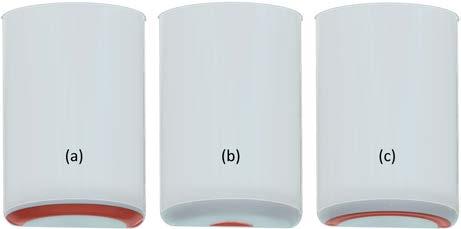
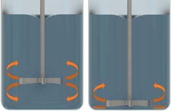
As can be observed in Figure 2 a & b the distributions of mixing effectiveness of the axial and radial impellers could be considered complimentary, with the axial impeller clearing the center-bottom of the beaker more effectively, and the radial impeller clearing the outer bottom more effectively. It was theorized that the weakness of the radial impeller resulted from the lower flow regime being effectively stalled due to the minimal impeller clearance as shown in Figure 3. It was thought that by introducing an axial flow component at the center of an
otherwise radial impeller, this mixing dead-zone could be reduced or eliminated. Effectively reversing the typical flow direction of the lower flow regime of the radial impeller and solving the dead zone created by the minimal clearance. This concept of a hybrid radial and axial impeller approach was termed a “raxial” impeller.
A prototype of this raxial impeller was designed in Autodesk Fusion 360, sliced with PrusaSlicer V2.4.2, and printed in ColorFabb HT on an enclosed Prusa i3MK3S+. A parametric design was employed to allow the area ratio between axial (central) and radial (outer) components to be easily varied in future iterations. This was to allow for easy optimisation in future for use in suspensions with differing properties. An initial effective area ratio of 1:12 was chosen. Total design and printing time to deliver this prototype solution was approximately 90 minutes.

Figure 2: Approximate patterns of last settled deposits to be cleared by each impeller type. (a) axial, (b) radial, (c) raxial

Figure 3: Radial impeller mixing pattern: upper and lower flow regimes, with optimum (left) and minimal (right) clearance.
Performance Testing
All three impeller designs were tested using the method outlined above. Results can be seen inTable 1, with the approximate distribution of settled deposits which were last to re-suspend shown in Figure 2. * 72 RPM technically resuspended all settled material but failed to effectively homogenize the suspension, with a visible higher density area between the center of the impeller and the bottom of the beaker, and visible stratification in the suspension density. This is likely due to the lesser

Figure 4: (a) axial, (b) radial, and (c) raxial impeller designs
vertical mixing effect of a radial impeller as compared to axial. Based on this the radial impeller could not be considered to have met the primary objective of effectively mixing the API solution for spraying.
In terms of force exerted on the scale, the radial impeller tested was noted to be superior to the axial, likely due to its force on the dispersion being primarily exerted in the horizontal plane, as compared to the axial impellers force being exerted along its vertical axis. The raxial impeller’s axial flow component likely adds slightly to the force it exerts, but could be considered a worthwhile design compromise to eliminate the radial impeller’s mixing dead-zone.
As can be seen from Table 1 the 3D printed raxial impeller scored considerably better than the axial design for both minimum RPM and force on the scale, while maintaining all API particles in suspension and visually achieving similarly effective inter-mixing throughout the suspension beaker.
Further Notes & Observations
• Based on the distribution of deposits just below re-suspension RPM with the raxial impeller, it could be concluded that the ratio of axial to radial effective area is somewhat higher than required, and that a slight reduction might create an impeller that resuspends all settled deposits at a lower RPM. • FDM printing at a coarse layer height of 0.25mm was used for speed in the production of the prototype impeller, which as demonstrated proved effective. The polymer used (ColorFabb
HT - Eastman Amphora HT5300) was selected for its solvent resistance and sufficient toughness to minimise the risk of brittle failure during use. • SLA / resin-based printing technologies do hold some advantages in this application due to the precision and smoothness of the exterior surfaces that can be produced. • Printing in this case was performed with non-GMP materials and equipment as the application
was non-GMP. FDA-approved food-safeFDM printing materials and printer configurations are available however, enabling similar problem-solving approaches in GMP applications.
Conclusions
• Changes in raw material suppliers can often impact established processes to the point of no longer meeting the Quality Target Product Profile (QTPP). While advanced control and automation methodologies core to the Industry 4.0 transition can handle many of these variations seamlessly, some necessitate manual intervention. • In this case a change in API supplier resulted in a multimodal particle size distribution, with the largest mode causing aggressive segregation of the mixed coating dispersion compared to previous batches executed. • Additive manufacturing technologies, even in GMP applications, can present opportunities for rapid problem-solving without reliance on external suppliers and potential supply chain delays. • Solutions customised to the specific application and problem can be very quickly developed, tested, and implemented, further supporting manufacturing efficiency. • The low cost of failure provided by these tools enables more creative engineering solutions to be trialed. In this case the solution was engineered not just to resolve the primary mixing issue, but also to successfully optimise against several secondary objectives, ultimately allowing further improvement of the implemented real time process automation.
AUTHOR BIO
Chris O’Callaghan is head of engineering within Innopharma Technology and is responsible for process analytical technologies and control products, applications development, and customer project delivery. He and his team manage the custom engineering projects required to successfully interface control systems with new and existing product lines in the continuous and batch manufacturing spaces, as well as control strategy development and deployment


