My Working Drawing Portfolio showcases my technical proficiency and attention to detail in architectural drafting. It features working drawings from my first two significant projects, alongside selected works from a total of six projects, illustrating my comprehensive experience.
FEATURED PROJECTS
RESIDENTIAL BUILDER FLOOR:
Site Plans, Floor Plans, Elevations, and Sections: Detailed layouts and structural details.
LUXURY RESIDENTIAL:
Structural, MEP, and Detail Drawings: Framework, essential systems integration, and intricate construction details.
I am skilled in AutoCAD, SketchUp, and Adobe Creative Suite, ensuring precision and clarity. I understand the scheduling of drawings, ensuring efficient project progression.
CONCLUSION
This portfolio demonstrates my ability to produce high-quality architectural drawings that support successful project execution.
| SETTING OUT PLAN
| EXCAVATION FRAWING
| STRUCTURE
| SITE PLAN
| FLOOR PLANS
| SLAB PROFILE
| SECTIONS
| WALL SECTIONS
| SHAFT DETAILS
| ELEVATION
| DOOR WINDOW SCHEDULE
| STAIRCASE DETAIL
| ELEVATOR DETAIL
| WET AREA DETAIL TOILET/KITCHEN | MECHANICAL | ELECTRCIAL | PLUMBING | MISCELLENEOUS
W1b W1c W1a C1b C1b C1a C2a C2b C2c C2b C2a C1b C1a C2b C1b A B 01 03 04 05 02 J I H E F C D G COLUMN SETTING OUT 1:60 @A3 SCALE: DRAWING TITLE: DRAWN BY VS CHECKED BY REV NO A377 DEFENCE COLONY New Delhi PRINCIPAL DESIGN CONSULTANT UnBox Design B-119, Ground Floor, East of Kailash, New Delhi 110065 STRUCTURAL CONSULTANT STAGE NAME STAMP NOTE: 1. All dimensions are in millimeters. 2. All levels are in millimeters. 3. This drawing is a copyright and property of the architect, is not to be produced, copied, handed over to third party or used for any other purpose other than for which is intended. 4. This drawing is to be read and not to be scaled. 5. All dimensions shall be verified on site prior to start of work any discrepancy shall be brought to the notice of the Architect. 6. The Contractor Project Manager must check all dimensions and details and be responsible for the same. Any discrepancy shall be notice of the Architect. 7. This drawing shall be read in conjunction with all relevant architectural, structural and services drawings. Any discrepancy noticed shall be brought to the attention of the consultants and resolved as soon as possible, but always prior to procurement execution of works. 8. All the services ducts cut-outs are to be covered after services provisions. 9. Drawing approval is for the conformity with outline design intent and does not relieve the contractor/ subcontractor from full responsibility for the accuracy, integration and fitness for purpose of design. 10. Construction Manager/Project Manager to revert back within 7 working days of receiving the drawings on coordination and buildability issues. otherwise it would be deemed that they have understood and accepted the drawing/design and own full responsibility for the works carried out accordingly. Brick wall R.C.C. Dry wall Partiton Stone LEGEND Grass Blockwork Wardrobe Level Drop R.C.C. For Review Purpose Rev. Date N REFERENCE POINT - 1 1553 230 1553 230 1553 230 1553 230 1553 230 230 3000 600 230 4884 230 600 2080 450 1235 230 600 2830 600 4884 600 230 230 230 230 230 230 4700 7300 200 1981 370 920 5085 600 2160 600 6847 920 3000 16812 230 3571 230 1820 1521 230 6933 230 3982 230 3115 230 570 450 2162 450 4100 600 1521 230 6933 230 1 Setting Out Plan 1:60 DRAWING NO REFERENCE POINT - 2 19812 9144 W1b W1c W1a C1b C1b C1a C2a C2b C2c C2b C2a C1b C1a C2b C1b A B 01 03 04 05 02 J I H E F C D G 300THK. 300THK. 300THK. 600THK. 600THK. 600THK. 600THK. 3650 4900 2050 1752 1465 1400 1020 1415 480 1463 3285 1445 1105 1895 1170 EXCAVATION 1:60 @A3 SCALE: DRAWING TITLE: DRAWN BY VS CHECKED BY REV NO A377 DEFENCE COLONY New Delhi PRINCIPAL DESIGN CONSULTANT UnBox Design B-119, Ground Floor, East of Kailash, New Delhi 110065 STRUCTURAL CONSULTANT STAGE NAME STAMP NOTE: 1. All dimensions are in millimeters. 2. All levels are in millimeters. 3. This drawing is a copyright and property of the architect, is not to be produced, copied, handed over to third party or used for any other purpose other than for which is intended. 4. This drawing is to be read and not to be scaled. 5. All dimensions shall be verified on site prior to start of work any discrepancy shall be brought to the notice of the Architect. 6. The Contractor Project Manager must check all dimensions and details and be responsible for the same. Any discrepancy shall be notice of the Architect. 7. This drawing shall be read in conjunction with all relevant architectural, structural and services drawings. Any discrepancy noticed shall be brought to the attention of the consultants and resolved as soon as possible, but always prior to procurement execution of works. 8. All the services ducts cut-outs are to be covered after services provisions. 9. Drawing approval is for the conformity with outline design intent and does not relieve the contractor/ subcontractor from full responsibility for the accuracy, integration and fitness for purpose of design. 10. Construction Manager/Project Manager to revert back within 7 working days of receiving the drawings on coordination and buildability issues. otherwise it would be deemed that they have understood and accepted the drawing/design and own full responsibility for the works carried out accordingly. Brick wall R.C.C. Dry wall Partiton Stone LEGEND Grass Blockwork Wardrobe Level Drop R.C.C. For Review Purpose Rev. Date N 16809 877 2125 9145 2125 874 16810 9145 19812 9144 Plot Line 1230 1920 1450 6465 13290 6465 4540 3580 6520 3580 2230 1230 1601 1450 600 1 Excavation Plan 1:60
X06 X05 Y02 Y01 X01 X02 X03 X04 X01 Y01 Y02 Y03 Y04 Y05 Y06 Y07 Y08 Y09 Y10 Y11 X02 X03 X04 X05 X06 X07 X08 X09 X10 X11 X12 X13 X14 X15 X16 X17 Y03 X07 Y02 Y01 X06 X05 X04 X03 X02 X01 1 Site Plan 1:125 UG TANK 5200lt 1800 W 1800 H 1600 Site Plan A- 101 Purpose Rev. Date SCALE: DRAWING NO DRAWING TITLE: DRAWN BY VS CHECKED BY REV NO NOTE: 1. All dimensions are in millimeters. 2. All levels are in millimeters. 3. This drawing copyright and property of the architect, not to be produced, copied, handed over to third party or used for any other purpose other than for which intended. 4. This drawing to be read and not to be scaled. 5. All dimensions shall be verified on site prior to start of work any discrepancy shall be brought to the notice of the Architect. 6. The Contractor Project Manager must check all dimensions and details and be responsible for the same. Any discrepancy shall be notice of the Architect. 7. This drawing shall be read in conjunction with all relevant architectural, structural and services drawings. Any discrepancy noticed shall be brought to the attention of the consultants and resolved as soon as possible, but always prior to procurement / execution of works. 8. All the services ducts cut-outs are to be covered after services provisions. 9. Drawing approval for the conformity with outline design intent and does not relieve the contractor/ subcontractor from full responsibility for the accuracy, integration and fitness for purpose of design. 10. Construction Manager/Project Manager to revert back within 7 working days of receiving the drawings on coordination and buildability issues. otherwise it would be deemed that they have understood and accepted the drawing/design and own full responsibility for the works carried out accordingly. PROJECT: SITE: EURONICS FARMHOUSE DERA MANDI, NEW DELHI PRINCIPAL DESIGN CONSULTANT CLIENT: MEP CONSULTANT STRUCTURAL CONSULTANT JAPAN SHAH CONSULTING ENGINEER 601, Sixth Floor, Silver Oaks Building, Near Mahalaxmi Cross Road, Paldi, Ahmedabad 380007 Mobile (direct): +91-94264 01793 JAIN FAMILY STAGE NAME 111 TOS +600 mm FFL +675 mm 112 TOS +600 mm FFL +675 mm 113 TOS +600 mm FFL +660 mm 110 TOS +600 mm FFL +675 mm 109 S1 TOS +600 mm FFL +675 mm 108 TOS +600 mm FFL +660 mm 107 TOS +600 mm FFL +675 mm Double Height Corridor 104 TOS +600 mm FFL +675 mm 105 TOS +600 mm FFL +675 mm 103 TOS +600 mm FFL +675 mm 102 TOS +600 mm FFL +675 mm TOS +600 mm FFL +675 mm 101 116 TOS +600 mm FFL +675 mm 114 TOS +600 mm FFL +675 mm 115 SWIMMING POOL DEPTH 1350mm(4.5 ft) TOS -750 Outside Sitting Deck 16050 x 3000 Deck 2250 x 10625 UP UP UP UP UP UP UP UP Front Lawn 28116mm 15156mm Entrance Porch Family Lawns 35588mm X 5640mm UG TANK 5200lt 1800 W 1800 H 1600 UG TANK 5200lt 1800 W 1800 H 1600 UG TANK 5200lt 1800 W 1800 1600 Front Main Road Courtyard N 118 119 120 121 122 123 124 125 123 122 FFL +150 mm FFL +300 mm Vehicular Entry/Exit Pedestrian Entry/Exit Guard Room Drive Way 01 02 03 04 05 06 07 08 09 10 11 12 13 14 15 16 17 18 19 20 23 22 24 25 26 44 43 41 40 27 28 29 30 31 32 33 34 35 36 37 38 39 Service Road Vehicular Entry/Exit Septic Tank Septic Tank Existing BoreWell 117 126 R0 Issued to PMC 23-12-2022 1:125 @A1 Reference Copy R0 21 42 For Detail Refer Drawing: A105.2 For Detail Refer Drawing: A105.1 ROOM INDEX -Ground Floor Name Room size (mm) Entrance Foyer Kitchen 4135 X 2690 Staircase/Lift Lobby 6875 X 4540 Room 102 101 105 106 107 108 Utility/Washing 2885 X 2690 Puja Room 4870 X 5525 2580 X 3060 Powder Room 109 110 111 112 113 114 115 Electrical room Dresser Toilet Grandparent BDR Living & Dining Room Swimming Pool Family Lounge 1800 x 1800 7250 x 7120 4500 x 7120 3600 x 3570 3485 x 3620 12600 x 7800 7450 x 8625 104 4135 X 6115 103 Entertainment Room 11320 X 7120 7050 X 8780 Service Area 116 Corridor 12470 x 2400 117 Courtyard 5500 x 7120 ROOM INDEX Ancillary Block Name Room size (mm) Room 118 119 120 121 122 123 124 Pump Room Powder Room (F) Staff Quarter Common Shower Toilet Pantry/Utility Powder Room (M) 3300 x 2270 3300 x 2715 1750 x 1952 3300 x 2800 4400 x 2700 2145 x 1750 2460 x 2515 125 Service/Store 1825 2515 126 DG Room 4860 3070 127 Guard Room 4415 3270 Existing Tree (to be moved)

Room ROOM INDEX - Stilt Floor Name Room size(mm) Stilt Parking Stair & Lift Lobby 201 202 203 204 205 206 3915 x 1390 Stair Lobby 1455 X 1540 Servant Toilet 2150 X 1350 Servant Room 1555 X 2200 Servant Room 2600 X 1570 1520 x 1650 SHAFT INDEX Type Shaft size (mm) Elevator Shaft S1 S2 1520 X 790 Plumbing Shaft no. S1 S2 201 206 204 205 202 206 206 DOOR SCHEDULE- STILT Type no. Rough opening size (mm) FFL to sill lvl 201 FFL to lintel lvl 00 202 203 204 205 00 00 00 00 1000 X 2100 201 202 203 204 205 206 207 D3 750 X 2100 206 207 00 00 x205 x206 WINDOW SCHEDULE- STILT Type no. Rough opening size (mm) FFL to sill lvl X201 FFL to lintel lvl 450 X 1000 X202 1750 450 X 1000 750 W3 TOS +200 FFL +260 2100 2100 Stilt Floor Staircase Floor to Floor Height:2700 No. of Steps 18 Tread 250mm Riser =150 mm Width 900 mm A A101 A203 B A101 A203 C A101 A203 STILT FLOOR PLAN 1:60 @A3 SCALE: DRAWN BY VS CHECKED BY REV NO For Review Purpose Rev. Date R0 R1 For Review 28-04-2023 For Review 22-05-2023 R2 For Review 03-08-2023 DRAWING TITLE: A377 DEFENCE COLONY New Delhi PRINCIPAL DESIGN CONSULTANT UnBox Design B-119, Ground Floor, East of Kailash, New Delhi 110065 STRUCTURAL CONSULTANT STAGE NAME STAMP NOTE: 1. All dimensions are in millimeters. 2. All levels are in millimeters. 3. This drawing is a copyright and property of the architect, is not to be produced, copied, handed over to third party or used for any other purpose other than for which is intended. 4. This drawing is to be read and not to be scaled. 5. All dimensions shall be verified on site prior to start of work any discrepancy shall be brought to the notice of the Architect. 6. The Contractor Project Manager must check all dimensions and details and be responsible for the same. Any discrepancy shall be notice of the Architect. 7. This drawing shall be read in conjunction with all relevant architectural, structural and services drawings. Any discrepancy noticed shall be brought to the attention of the consultants and resolved as soon as possible, but always prior to procurement execution of works. 8. All the services ducts cut-outs are to be covered after services provisions. 9. Drawing approval is for the conformity with outline design intent and does not relieve the contractor/ subcontractor from full responsibility for the accuracy, integration and fitness for purpose of design. 10. Construction Manager/Project Manager to revert back within 7 working days of receiving the drawings on coordination and buildability issues. otherwise it would be deemed that they have understood and accepted the drawing/design and own full responsibility for the works carried out accordingly. Brick wall R.C.C. Dry wall Partiton Stone LEGEND Grass Blockwork Wardrobe Level Drop R.C.C. N JAPAN SHAH CONSULTING ENGINEER 601, Sixth Floor, Silver Oaks Building, Near Mahalaxmi Cross Road, Paldi, Ahmedabad 380007 1 STILT 1:60 600 345 600 230 9144 19812 5085 600 2160 3000 4770 450 330 450 310 230 1520 230 4100 450 2165 450 570 230 3985 920 3000 4510 230 4030 600 1565 1150 600 1460 385 750 300 750 100 1460 450 750 75 270 450 750 75 100 750 75 5000 600 115 370 230 3115 230 600 2080 450 1235 230 1750 790 1650 1520 1000 75 230 630 560 115 115 2110 230 2760 2760 2760 1820 230 230 930 360 470 185 800 590 3380 675 920 6850 920 3985 145 245 145 135 450 135 203 TOS +200 FFL +275 x204 x203 x202 X203 450 X 1000 X204 450 X 800 1200 X205 450 X 800 1200 D1 D1 D1 D1 D1 D1 x201 X206 560 X 700 1650 2325 TOS +200 FFL +275 W2 W3 W3 W4 W4 2000 2000 1750 750 1750 750 I.C. 600 600 MM I.C. I.C. I.C. I.C. S5 S4 S4 S5 Plumbing Shaft Plumbing Shaft 445 X 465 800 X 185 R1 2100 2100 2100 2100 2100 750 X 2100 750 X 2100 750 X 2100 750 X 2100 750 X 2100 1 2 3 4 5 6 7 10 11 12 13 14 15 16 17 18 UP DN DN -1 -2 -3 -4 -5 -6 -7 -8 -9 -10 -11 -12 A B 01 03 04 05 02 J I H E F C D G DB Room ROOM INDEX - Basement Name Room size(mm) Stair & Lift Lobby 301 302 303 304 305 306 307 308 309 310 311 312 Bedroom 1 Bedroom 1 Toilet Balcony Living And Dinning Central Lobby Kitchen Bedroom 2 Bedroom 2 Toilet Balcony 2 Bedroom 3 301 303 302 305 306 304 309 310 311 312 313 308 307 313 Bedroom 3 Toilet Powder Room 3570 x 4790 1570 x 4790 8915 x 2100 3560 x 7655 1350 x 2340 3800 x 2500 1370 x 2130 3530 x 3170 3530 x 1400 3480 x 4570 4570 x 1570 3915 x 1390 2045 x 3515 x308 x307 x306 x302 x303 x304 DOOR SCHEDULE- GROUND FLOOR Type S no. Rough opening size (mm) FFL to sill lvl 301 FFL to lintel lvl 00 3000 302 303 304 305 306 D1 00 00 00 00 00 1000 X 3000 D3 D3 D2 D3 D2 1000 X 2400 900 X 2400 750 X 2400 1000 X 2400 900 X 2400 307 308 00 00 D3 D2 1000 X 2400 900 X 2400 WINDOW SCHEDULE- GROUND FLOOR Type S no. Rough opening size (mm) FFL to sill lvl X301 FFL to lintel lvl X303 X304 X305 X302 W5 600 X 2675 450 W8 2400 X 1500 900 X306 DW1 2400 X 3200 -75 3125 DW1 2400 X 3200 -75 W7 600 X 1500 900 DW2 1900 X 2475 -75 301 302 303 304 305 306 308 309 310 309 00 D3 1000 X 2400 x305 X307 W6 600 X 1200 1200 S3 S1 TOS +2900 FFL +2975 TOS +2900 FFL +2960 TOS +2900 FFL +2960 TOS +2900 FFL +2975 TOS +2900 FFL +2975 TOS +2900 FFL +2975 TOS +2900 FFL +2975 TOS +2900 FFL +2975 TOS +2900 FFL +2960 TOS +2900 FFL +2975 TOS +2900 FFL +2960 2400 2400 2400 2400 2400 2400 2400 2400 3125 3125 x309 X308 W7 600 X 1950 450 Stilt Floor Staircase Floor to Floor Height:3700 No. of Steps 20 Tread 250mm Riser =185 mm Width 900 mm A A101 A203 B A101 A203 C A101 A203 TYPICAL FLOOR PLAN 1:60 @A3 SCALE: DRAWN BY VS CHECKED BY REV NO For Review Purpose Rev. Date R0 R1 For Review 28-04-2023 For Review 22-05-2023 R2 For Review 03-08-2023 DRAWING TITLE: A377 DEFENCE COLONY New Delhi PRINCIPAL DESIGN CONSULTANT UnBox Design B-119, Ground Floor, East of Kailash, New Delhi 110065 STRUCTURAL CONSULTANT STAGE NAME STAMP NOTE: 1. All dimensions are in millimeters. 2. All levels are in millimeters. 3. This drawing is a copyright and property of the architect, is not to be produced, copied, handed over to third party or used for any other purpose other than for which is intended. 4. This drawing is to be read and not to be scaled. 5. All dimensions shall be verified on site prior to start of work any discrepancy shall be brought to the notice of the Architect. 6. The Contractor Project Manager must check all dimensions and details and be responsible for the same. Any discrepancy shall be notice of the Architect. 7. This drawing shall be read in conjunction with all relevant architectural, structural and services drawings. Any discrepancy noticed shall be brought to the attention of the consultants and resolved as soon as possible, but always prior to procurement execution of works. 8. All the services ducts cut-outs are to be covered after services provisions. 9. Drawing approval is for the conformity with outline design intent and does not relieve the contractor/ subcontractor from full responsibility for the accuracy, integration and fitness for purpose of design. 10. Construction Manager/Project Manager to revert back within 7 working days of receiving the drawings on coordination and buildability issues. otherwise it would be deemed that they have understood and accepted the drawing/design and own full responsibility for the works carried out accordingly. Brick wall R.C.C. Dry wall Partiton Stone LEGEND Grass Blockwork Wardrobe Level Drop R.C.C. N JAPAN SHAH CONSULTING ENGINEER 601, Sixth Floor, Silver Oaks Building, Near Mahalaxmi Cross Road, Paldi, Ahmedabad 380007 1 GROUND FLOOR 1:60 Align S2 230 3420 615 2400 500 230 115 600 230 600 4100 450 2165 450 570 2110 1235 230 3985 920 2100 600 5085 600 2160 600 6850 920 2100 810 600 600 2160 600 830 670 600 230 1900 1000 235 115 3685 760 1000 2570 600 485 745 600 2080 450 115 1000 390 600 2830 370 1150 485 4790 4905 2750 1750 790 1520 1650 230 750 1495 1000 760 115 2110 1000 4580 1520 1260 115 3535 2265 1140 805 7650 2040 1275 1035 600 900 2595 1520 2400 3430 1000 150 75 485 230 115 560 115 230 120 115 235 600 1565 3400 3420 805 2520 900 565 805 270 115 1000 1020 115 1465 805 230 600 115 230 700 2400 490 2400 945 230 600 1215 1260 900 230 230 1820 230 115 900 790 4045 145 900 4090 1980 2060 115 115 230 115 615 2400 2400 2400 2400 2400 x301 X309 TOS +2900 FFL +2975 TOS +2825 FFL +2900 560 X 790 2335 3125 W2 307 D3 1000 X 2400 00 2400 310 S4 S5 1520 x 1650 SHAFT INDEX Type Shaft size (mm) Elevator Shaft S1 S2 1520 X 790 Plumbing Shaft S no. S3 S4 S5 Plumbing Shaft Plumbing Shaft Plumbing Shaft 600 X 1275 445 X 465 800 X 185 R1 1 2 3 4 5 6 7 8 9 10 11 12 13 14 15 16 17 18 19 20 UP DN DB SLOPE SLOPE SLOPE SLOPE JAAL EXTENDED 2FT AHEAD SLOPE SLOPE

STILT FLOOR PLAN 1:60 @A3 SCALE: DRAWN BY VS CHECKED BY REV NO For Review Purpose Rev. Date R0 For Review 25-05-2023 DRAWING TITLE: A377 DEFENCE COLONY New Delhi PRINCIPAL DESIGN CONSULTANT UnBox Design B-119, Ground Floor, East of Kailash, New Delhi 110065 STRUCTURAL CONSULTANT STAGE NAME STAMP NOTE: 1. All dimensions are in millimeters. 2. All levels are in millimeters. 3. This drawing is a copyright and property of the architect, is not to be produced, copied, handed over to third party or used for any other purpose other than for which is intended. 4. This drawing is to be read and not to be scaled. 5. All dimensions shall be verified on site prior to start of work any discrepancy shall be brought to the notice of the Architect. 6. The Contractor Project Manager must check all dimensions and details and be responsible for the same. Any discrepancy shall be notice of the Architect. 7. This drawing shall be read in conjunction with all relevant architectural, structural and services drawings. Any discrepancy noticed shall be brought to the attention of the consultants and resolved as soon as possible, but always prior to procurement / execution of works. 8. All the services ducts cut-outs are to be covered after services provisions. 9. Drawing approval is for the conformity with outline design intent and does not relieve the contractor/ subcontractor from full responsibility for the accuracy, integration and fitness for purpose of design. 10. Construction Manager/Project Manager to revert back within 7 working days of receiving the drawings on coordination and buildability issues. otherwise it would be deemed that they have understood and accepted the drawing/design and own full responsibility for the works carried out accordingly. Brick wall R.C.C. Dry wall Partiton Stone LEGEND Grass Blockwork Wardrobe Level Drop R.C.C. N JAPAN SHAH CONSULTING ENGINEER 601, Sixth Floor, Silver Oaks Building, Near Mahalaxmi Cross Road, Paldi, Ahmedabad 380007 150mm thk +2650 mm 150mm thk +2650 mm 150mm thk +2650 mm 150mm thk +2650 mm 150mm thk +2650 mm 150mm thk +2650 mm 150mm thk +2650 mm 150mm thk +2650 mm 150mm thk +2650 mm 150mm thk +2650 mm 150mm thk +2650 mm 150mm thk +2650 mm 150mm thk +2650 mm 1415 3285 1170 1445 1020 480 1400 1465 4900 3650 1465 2050 1750 1 Slab Profile : Stilt Roof 1:60 S4 S1 S2 S3 1520 790 1520 1650 600 1270 465 445 100MM DIA 2 X SLEEVES FOR PLUMBING SHAFT 125MM DIA EXHAUST SLEEVES 100MM DIA 2 X SLEEVES FOR PLUMBING SHAFT 100MM DIA 2 X SLEEVES FOR PLUMBING 150 150 150 100 150 150 150 2 Beam Detail 1:30 150 150 100 100 75MM DIA 2 X SLEEVES FOR ELECTRICAL 75MM DIA 2 X SLEEVES FOR ELECTRICAL 75MM DIA 2 X SLEEVES FOR ELECTRICAL 75MM DIA 2 X SLEEVES FOR ELECTRICAL 75MM DIA 2 X SLEEVES FOR ELECTRICAL 75MM DIA 2 X SLEEVES FOR ELECTRICAL 75MM DIA 2 X SLEEVES FOR ELECTRICAL 75MM DIA 2 X SLEEVES FOR ELECTRICAL 75MM DIA 2 X SLEEVES FOR ELECTRICAL 75MM DIA 2 X SLEEVES FOR ELECTRICAL 75MM DIA 2 X SLEEVES FOR ELECTRICAL 75MM DIA 2 X SLEEVES FOR ELECTRICAL 1250 150 1870 150 150 3650 230 900 150 1185 150 150 150 150 2970 150 150 2835 315 150 2305 1620 180 900 150 1185 750 150 2600 150 150 150 150 1070 100MM DIA 2 X SLEEVES FOR PLUMBING SHAFT 100MM DIA SLEEVE FOR PLUMBING 150 R0 A B 01 03 04 05 02 J H E F C D G 3-16 (B) 8 150 C/C LINKS 8 75 C/C LINKS Beam cover as/Structure 4 inch sleeve as/site AS/STR C/C LINKS AS/STR 3-16 (B) AS/STR GROUND FLOOR PLAN 1:60 @A3 SCALE: DRAWN BY VS CHECKED BY REV NO For Review Purpose Rev. Date R0 For Review 25-05-2023 DRAWING TITLE: A377 DEFENCE COLONY New Delhi PRINCIPAL DESIGN CONSULTANT UnBox Design B-119, Ground Floor, East of Kailash, New Delhi 110065 STRUCTURAL CONSULTANT STAGE NAME STAMP NOTE: 1. All dimensions are in millimeters. 2. All levels are in millimeters. 3. This drawing is a copyright and property of the architect, is not to be produced, copied, handed over to third party or used for any other purpose other than for which is intended. 4. This drawing is to be read and not to be scaled. 5. All dimensions shall be verified on site prior to start of work any discrepancy shall be brought to the notice of the Architect. 6. The Contractor Project Manager must check all dimensions and details and be responsible for the same. Any discrepancy shall be notice of the Architect. 7. This drawing shall be read in conjunction with all relevant architectural, structural and services drawings. Any discrepancy noticed shall be brought to the attention of the consultants and resolved as soon as possible, but always prior to procurement execution of works. 8. All the services ducts cut-outs are to be covered after services provisions. 9. Drawing approval is for the conformity with outline design intent and does not relieve the contractor/ subcontractor from full responsibility for the accuracy, integration and fitness for purpose of design. 10. Construction Manager/Project Manager to revert back within 7 working days of receiving the drawings on coordination and buildability issues. otherwise it would be deemed that they have understood and accepted the drawing/design and own full responsibility for the works carried out accordingly. Brick wall R.C.C. Dry wall Partiton Stone LEGEND Grass Blockwork Wardrobe Level Drop R.C.C. N JAPAN SHAH CONSULTING ENGINEER 601, Sixth Floor, Silver Oaks Building, Near Mahalaxmi Cross Road, Paldi, Ahmedabad 380007 +6550 mm 150mm thk +6550 mm 150mm thk +6550 mm 150mm thk +6550 mm 150mm thk +6550 mm 150mm thk +6550 mm 150mm thk +6550 mm 150mm thk +6550 mm 150mm thk +6550 mm 150mm thk +6550 mm 150mm thk +6550 mm 150mm thk +6550 mm 150mm thk +6550 mm 150mm thk 1415 3285 1170 1445 1020 480 1400 1465 4900 3650 1465 2050 1750 1500 9144 1 Slab Profile : Ground Floor Roof Slab 1:60 S4 S1 S2 S3 600 1270 1520 790 1520 1650 465 445 75MM DIA 2 X SLEEVES FOR ELECTRICAL 75MM DIA 2 X SLEEVES FOR ELECTRICAL 75MM DIA 2 X SLEEVES FOR ELECTRICAL 75MM DIA 2 X SLEEVES FOR ELECTRICAL 75MM DIA 2 X SLEEVES FOR ELECTRICAL 125MM DIA EXHAUST SLEEVES 125MM DIA 2 X SLEEVES FOR EXHAUST AND CHIMNEY 125MM DIA PLUMBING SLEEVE 75MM DIA 2 X SLEEVES FOR ELECTRICAL 75MM DIA 2 X SLEEVES FOR ELECTRICAL 75MM DIA 2 X SLEEVES FOR ELECTRICAL 125MM DIA 2 X SLEEVES FOR PLUMBING SHAFT 75MM DIA 2 X SLEEVES FOR ELECTRICAL 75MM DIA 2 X SLEEVES FOR ELECTRICAL 150MM DIA 3 X SLEEVES FOR HVAC 150MM DIA 2 X SLEEVES FOR HVAC 150MM DIA SLEEVES FOR HVAC 150MM DIA X SLEEVES FOR HVAC 125MM DIA SLEEVES FOR HVAC 1250 150 1570 150 600 750 150 2600 150 150 2605 150 1280 150 1185 150 150 1185 150 900 150 150 100 150 150 150 2565 150 375 100 100 150 315 150 2305 1990 2730 150 150 150 4220 150 150 2970 150 150 2830 100 100 125 350 125 595 125 350 150 150 150 495 150 150 EQ EQ 150 815 150 150 150 150 150 150 150 185 150 150 185 150 150 150 +6475mm 150mm thk 150MM DIA 2 X SLEEVES FOR HVAC 75MM DIA 2 X SLEEVES FOR ELECTRICAL 75MM DIA 2 X SLEEVES FOR ELECTRICAL 75MM DIA 4 X SLEEVES FOR ELECTRICAL 75MM DIA 2 X SLEEVES FOR ELECTRICAL 75MM DIA 2 X SLEEVES FOR ELECTRICAL 125MM DIA SLEEVE FOR PLUMBING 75MM DIA 2 X SLEEVES FOR ELECTRICAL 150MM DIA SLEEVE FOR HVAC 125MM DIA 2 X SLEEVES FOR PLUMBING SHAFT 125MM DIA 2 X SLEEVES FOR PLUMBING SHAFT 125MM DIA EXHAUST SLEEVES R0 A B 01 03 04 05 02 J H E F C D G

607 703 603 ± 00 +150 mm +2850 mm +5850 mm +8850 mm +11850 mm +15865 mm TOS- TERRACE TOS- SECOND FLOOR TOS- FIRST FLOOR TOS- GROUND FLOOR TOS STILT +18865mm TOS- MUMTY ROOF FRONT ROAD LVL TOS- THIRD FLOOR -3850 mm TOS- BASEMENT -600 mm SER. ROAD 1 Section - AA' 1:75 606 604 603 x302 507 505 502 504 505 501 503 405 402 401 305 303 302 303 301 203 202 207 205 105 104 103 106 104 103 x703 3250 600 150 2700 3000 3000 3000 4015 3000 15865 Issued to PMC 20-10-2022 R0 1:75 @A2 Purpose Rev. Date SCALE: DRAWING NO DRAWING TITLE: DRAWN BY VS CHECKED BY AB REV NO PRINCIPAL DESIGN CONSULTANT MEP CONSULTANT STRUCTURAL CONSULTANT STAGE NAME STAMP NOTE: 1. All dimensions are in millimeters. 2. All levels are in millimeters. 3. This drawing is a copyright and property of the architect, is not to be produced, copied, handed over to third party or used for any other purpose other than for which it is intended. 4. This drawing is to be read and not to be scaled. 5. All dimensions shall be verified on site prior to start of work any discrepancy shall be brought to the notice of the Architect. 6. The Contractor / Project Manager must check all dimensions and details and be responsible for the same. Any discrepancy shall be notice of the Architect. 7. This drawing shall be read in conjunction with all relevant architectural, structural and services drawings. Any discrepancy noticed shall be brought to the attention of the consultants and resolved as soon as possible, but always prior to procurement / execution of works. 8. All the services ducts / cut-outs are to be covered after services provisions. 9. Drawing approval is for the conformity with outline design intent and does not relieve the contractor/ subcontractor from full responsibility for the accuracy, integration and fitness for purpose of design. 10. Construction Manager/Project Manager to revert back within working days of receiving the drawings on coordination and buildability issues. If otherwise it would be deemed that they have understood and accepted the drawing/design and own full responsibility for the works carried out accordingly. PROJECT: SITE: CLIENT: JAPAN SHAH CONSULTING ENGINEER 601, Sixth Floor, Silver Oaks Building, Near Mahalaxmi Cross Road, Paldi, Ahmedabad 380007 Mobile (direct): +91-94264 01793 Gandhi Town House New Delhi UnBox Design Mr. Kovid Gandhi B-119, Ground Floor, East of Kailash, New Delhi - 110065 Good For Construction A-201 Section - AA' Key Plan G H F E D C B A 1670 X 1990 S3 SHAFT INDEX Type Shaft size (mm) Elevator Shaft S1 1000 X 1125 Plumbing Shaft 1 S2 200 X 692 Electrical Shaft S4 1250 X 600 Plumbing Shaft 2 S5 1000 X 1000 Lift Shaft Room ROOM INDEX - Terrace Floor Name Room size(mm) Terrace Stair & Lift Lobby Store 701 702 703 704 705 3020 X 4300 3770 X 1590 Powder Room 7920 X 13630 2370 X 1590 1785 X 1920 Utility Room Room ROOM INDEX - Basement Name Room size(mm) Store Room Stair & Lift Lobby Massage Room Powder Room Gym 101 102 103 104 105 106 4540 X 3075 2640 X 3615 4350 X 4860 5770 X 7425 2825 X 3660 2485X 3435 107 1785 X 1920 Kids Play Room Electrical Room Room ROOM INDEX - Stilt Floor Name Room size(mm) Stilt Parking Stair & Lift Lobby Driver's Toilet Utility/Laundry Staff Toilet 201 202 203 204 205 206 4655 X 6000 7915 X 11500 4290 X 5270 1900 X 2885 1885 X 1260 1885 X 3900 207 Staff Quarter Utility Balcony 3280 X 3960 208 CCTV Room 1785 X 1920 Room ROOM INDEX - Ground Floor Name Room size(mm) Formal Living Stair & Lift Lobby 301 302 303 304 305 306 4540 X 4140 7900 X 9265 4135 X 6945 2030 X 4055 Rear Balcony 307 Front Balcony 308 Guest Bedroom Guest Toilet Electrical Room Room ROOM INDEX - First Floor Name Room size(mm) Side Balcony Stair & Lift Lobby Utility Balcony Kitchen Store Kitchen 401 402 403 404 405 406 4540 X 4140 6575 X 4625 4320 X 6945 1735 X 3370 Powder Room 407 1860 X 1985 Dining Area 408 Electrical Room Room ROOM INDEX - Second Floor Name Room size(mm) Puja Stair & Lift Lobby Toilet Lounge Study 501 502 503 504 505 506 4540 X 4140 5630 X 5025 2150 X 5025 6580 X 4140 507 3535 X 2890 Front Balcony Parents Bedroom 508 4130 X 6945 Rear Balcony Parents Toilet 509 510 511 2030 X 4060 3155 X 1070 Electrical Room Room ROOM INDEX - Third Floor Name Room size(mm) Side Balcony Family Living Master Toilet Master Dresser Master Bedroom 601 602 603 604 605 606 4540 X 4140 5630 X 6160 2150 X 6090 4420 X 3085 Kids Bedroom 607 4130 X 6945 Front Balcony Kids Dresser 608 2285 X 1865 Rear Balcony Kids Toilet 609 610 611 2040 X 5035 Electrical Room Bar/Service 3845 X 2830 512 Pantry/Bar Side Balcony 1785 X 1920 6400 X 1500 3045 X 2620 3045 X 2620 3270 X 1865 1785 X 1920 3045 X 2620 1785 X 1920 3270 X 1865 6400 X 1500 3045 X 2620 1785 X 1920 3270 X 1865 6400 X 1500 1850 750 2600 Dumbwaiter Shaft 1000 8850 WINDOW SCHEDULE- STILT FLOOR Type S no. Rough opening size (mm) FFL to sill lvl X201 FFL to lintel lvl W1 750 X 975 X202 1200 2175 W2 750 X 2025 X203 300 2325 WINDOW SCHEDULE- GROUND FLOOR Type S no. Rough opening size (mm) FFL to sill lvl X301 FFL to lintel lvl X303 X304 W4 750 X 2175 300 2475 X305 1590 X 2550 X302 2475 W3 DW1 6080 X 2550 -75 2475 DW2 1800 X 2475 00 2475 -75 WINDOW SCHEDULE- FIRST FLOOR Type S no. Rough opening size (mm) FFL to sill lvl X401 FFL to lintel lvl W10 750 X 1275 900 2475 X405 6080 X 2550 2475 X404 -75 X403 X402 DW3 2580 X 2550 -75 2475 W5 DW2 1800 X 2475 00 2475 WINDOW SCHEDULE- SECOND FLOOR Type S no. Rough opening size (mm) FFL to sill lvl DW4 4000 X 2675 X501 FFL to lintel lvl 2600 DW2 W4 750 X 2175 1800 X 2475 300 2475 2475 X503 X506 00 X507 -75 X502 X504 X505 3154 X 2025 700 2725 W4 750 X 2175 300 2475 W6 W7 Curtain Glazing as/detail WINDOW SCHEDULE- THIRD FLOOR Type S no. Rough opening size (mm) FFL to sill lvl X601 FFL to lintel lvl DW2 1800 X 3300 3300 X603 X606 00 X607 X602 X604 X605 DW3 2580 X 3565 -75 B.O.B DW4 4000 X 3565 B.O.B -75 W8 750 X 3000 300 3300 W8 750 X 3000 300 3300 W7 Curtain Glazing as/detail WINDOW SCHEDULE- TERRACE Type S no. Rough opening size (mm) W9 750 X 1175 X704 FFL to lintel lvl 2375 W9 750 X 1175 1200 X705 1200 2375 X703 X702 X701 FFL to sill lvl DW3 2580 X 2300 00 2650 X 2300 00 DW5 2300 2300

R0 1:50 @A2 Purpose Rev. Date SCALE: DRAWING NO DRAWING TITLE: DRAWN BY VS CHECKED BY AB REV NO PRINCIPAL DESIGN CONSULTANT MEP CONSULTANT STRUCTURAL CONSULTANT STAGE NAME STAMP NOTE: 1. All dimensions are in millimeters. 2. All levels are in millimeters. 3. This drawing is a copyright and property of the architect, is not to be produced, copied, handed over to third party or used for any other purpose other than for which it is intended. 4. This drawing is to be read and not to be scaled. 5. All dimensions shall be verified on site prior to start of work any discrepancy shall be brought to the notice of the Architect. 6. The Contractor / Project Manager must check all dimensions and details and be responsible for the same. Any discrepancy shall be notice of the Architect. 7. This drawing shall be read in conjunction with all relevant architectural, structural and services drawings. Any discrepancy noticed shall be brought to the attention of the consultants and resolved as soon as possible, but always prior to procurement / execution of works. 8. All the services ducts / cut-outs are to be covered after services provisions. 9. Drawing approval is for the conformity with outline design intent and does not relieve the contractor/ subcontractor from full responsibility for the accuracy, integration and fitness for purpose of design. 10. Construction Manager/Project Manager to revert back within 7 working days of receiving the drawings on coordination and buildability issues. If otherwise it would be deemed that they have understood and accepted the drawing/design and own full responsibility for the works carried out accordingly. PROJECT: SITE: CLIENT: JAPAN SHAH CONSULTING ENGINEER 601, Sixth Floor, Silver Oaks Building, Near Mahalaxmi Cross Road, Paldi, Ahmedabad 380007 Mobile (direct): +91-94264 01793 Brick wall R.C.C. Dry wall Partiton Stone LEGEND Grass Blockwork Wardrobe Level Drop Gandhi Town House New Delhi UnBox Design Mr. Kovid Gandhi B-119, Ground Floor, East of Kailash, New Delhi 110065 Advance Copy N Wall Sections A-209.1 ± 00 +150 mm +2850 mm +5850 mm +8850 mm +11850 mm +15865 mm TOS- TERRACE TOS- SECOND FLOOR TOS- FIRST FLOOR TOS- GROUND FLOOR TOS - STILT FRONT ROAD LVL TOS- THIRD FLOOR -600 mm SER. ROAD -3850 mm TOS- BASEMENT 1 Wall Section - 1 1:50 25mm thk coping stone sloped to drain Exterior Wall finish detail as/Contractor 230mm thk Brick wall 25mm thk Stone Flooring finish as/Selection 75mm P.C.C laid in slope 55mm Insulation & water proofing as/specs from 'Roofers Combine' Glass Railing 10-12mm thk stone tile flooring laid to slope 115mm high R.C.C toe wall MS Plate fixed to beam detail as/contractor False Celing Finish as/Architect Glass Railing 35-45mm thk chapp plaster 6mm thk MS jaali welded over 6mm thk MS Sheet 100 x 200 mm thk MS box section C/C 600mm 25mm thk stone laid over 50mm screeding False ceiling as/Interior 25mm thk stone laid over 50mm screeding False ceiling as/Architect False Celing +5600 from Ground floor FFL Finish as/Selection 25mm thk stone laid over 50mm screeding 1000mm high from FFL MS railing detail as/Elevation 100mm high Stone skirting 25mm thk coping stone sloped to drain Boundary wall stone cladding as/approved sample (Refer Boundary wall detail) Fixing Dry clad as/contractor Planter as/detail 25mm thk coping stone sloped to drain 450x450x450 Inspection chamber 230mm thk basment R.C.C wall detail as/structure 75mm thk Guniting specs as/contractor 115mm thk internal brick wall 600mm R.C.C raft slab detail as/Structure False ceiling as/Interior KEY PLAN 1 1 3 3 4 4 6 6 5 5 8 8 9 9 7 7 2 2 A209.1A209.1 1 100 x 100 mm thk MS box section C/C 600mm Glass Railing fixing as/vendor 100mm stone skirting 25mm thk stone laid over 50mm screeding SS frame for railing fixing as/vendor 10x10mm drip edge groove Exterior wall plaster finish as/selection 230mm thk brick wall Glass Railing as/vendor 100mm stone skirting 6mm thk MS jaali welded over 6mm thk MS Sheet 100 x 100 mm thk MS box section (grid 600x600) 100 x 200 mm thk MS box section 230mm thk brick wall 100mm stone skirting on Terrace 75mm P.C.C laid in slope 55mm Insulation & water proofing as/specs from 'Roofers Combine' Exterior wall plaster finish as/selection 10 x 10 grove in plaster Window glazing detail as/vendor False ceiling as/Interior 230 170 R.C.C lintel detail as/structure 230mm thk brick wall 20mm thk stone jamb Window glazing detail as/vendor 230mm thk brick wall Height: 300mm from FFL 200mm thk R.C.C slab detail as/structure 3.5" x 1.5" MS hollow pipe 3.0" x1.5" MS hollow pipe Minimal glazing detail as/vendor 6 Detail - 4 1:15 4 Detail - 3 1:15 3 Detail - 2 1:15 2 Detail - 1 1:15 ± 00 +150 mm +2850 mm +5850 mm +8850 mm +11850 mm +15865 mm TOS- TERRACE TOS- SECOND FLOOR TOS- FIRST FLOOR TOS- GROUND FLOOR TOS STILT FRONT ROAD LVL TOS- THIRD FLOOR -600 mm SER. ROAD -3850 mm TOS- BASEMENT 5 Wall Section - 2 1:50 25mm thk coping stone sloped to drain 230mm thk Brick wall Exterior Wall plaster finish as/Selection 75mm P.C.C laid in slope 55mm Insulation & water proofing as/specs from 'Roofers Combine' 100mm stone skirting 20mm thk Stone Jamb Toilet window detail as/vendor False ceiling as/Interior Glass Railing 115mm high R.C.C toe wall 100mm Stone skirting Glass Railing 100mm Stone skirting 20mm thk Stone Jamb 6mm thk MS jaali welded over 6mm thk MS Sheet 100 200 mm thk MS box section Minimal fixed window section as/vendor Metal plate cladded to beam finish as/Selection Metal railing fixed over MS L-Section 115mm high R.C.C toe wall 25mm thk stone laid over 50mm screeding 25mm thk stone ramp Slope 1:5 230mm thk basment R.C.C wall 75mm thk Guniting specs as/contractor 115mm thk internal brick wall 600mm R.C.C raft slab detail as/Structure 25mm thk stone laid over 50mm screeding False ceiling as/Interior A209.1A209.1 3 A209.1A209.1 4 5 170x230 mm R.C.C Linte detail as/structure 230mm thk brick wall 230x450 mm R.C.C beam detail as/Structure 100 x 100 mm thk MS box section Grid size 600mm x 600mm 7 Detail - 5 1:15 Minimal Fixed glazing detail as/vendor 10mm thk MS plate 3.5" x 2.0" MS hollow pipe 3.0" x 2.0" MS hollow pipe 450 x 230mm R.C.C beam detail as/structure 1.0" x 1.5" MS hollow pipe Minimal sliding glazing detail as/vendor 10mm thk MS plate fixed to beam detail as/contractor 2 A209.1A209.1 1 2 25mm thk stone coping 100 100 20mm thk stone jamb 10 x 10mm grove in plaster 230mm thk Brick wall 100mm stone skirting 10-12mm thk stone tile flooring laid in slope 115mm high R.C.C toe wall MS Plate fixed to beam detail as/contractor 25mm thk stone coping 100mm stone skirting 10-12mm thk stone tile flooring laid in slope MS Base plate fixed to slab detail as/contractor MS Plate fixed to beam detail as/contractor 115mm high R.C.C toe wall 25mm thk stone laid over 50mm screeding SS frame for railing fixing as/vendor 10x10mm drip edge groove MS Plate fixed to beam detail as/contractor 115mm high R.C.C toe wall 35-45mm thk chapp plaster False ceiling finish as/selection detail as/vendor False ceiling finish as/selection detail as/vendor Wall plaster finish as/interior 230 450 mm RCC beam detail as/Structure 25mm thk Stone Flooring finish as/Selection 200mm thk RCC slab detail as/structure 25mm thk Stone Flooring finish as/Selection MS Plate fixed to beam detail as/contractor 25mm thk stone coping 10-12mm thk stone tile flooring laid in slope False ceiling finish as/selection detail as/vendor 115mm high R.C.C toe wall MS Plate fixed to beam detail as/contractor 25mm thk stone coping 35-45mm thk chapp plaster 10-12mm thk stone tile flooring laid in slope MS Plate fixed to beam detail as/contractor False ceiling finish as/selection detail as/vendor 10-12mm thk stone tile flooring laid in slope 100mm Stone skirting 10-12mm thk stone tile flooring laid in slope Y01 Y01


Issued to PMC 20-10-2022 R0 1:75 @A2 Purpose Rev. Date SCALE: DRAWING NO DRAWING TITLE: DRAWN BY VS CHECKED BY AB REV NO PRINCIPAL DESIGN CONSULTANT MEP CONSULTANT STRUCTURAL CONSULTANT STAGE NAME STAMP NOTE: 1. All dimensions are in millimeters. 2. All levels are in millimeters. 3. This drawing a copyright and property of the architect, is not to be produced, copied, handed over to third party or used for any other purpose other than for which it is intended. 4. This drawing is to be read and not to be scaled. 5. All dimensions shall be verified on site prior to start of work any discrepancy shall be brought to the notice of the Architect. 6. The Contractor / Project Manager must check all dimensions and details and be responsible for the same. Any discrepancy shall be notice of the Architect. 7. This drawing shall be read in conjunction with all relevant architectural, structural and services drawings. Any discrepancy noticed shall be brought to the attention of the consultants and resolved as soon as possible, but always prior to procurement execution of works. 8. All the services ducts / cut-outs are to be covered after services provisions. 9. Drawing approval is for the conformity with outline design intent and does not relieve the contractor/ subcontractor from full responsibility for the accuracy, integration and fitness for purpose of design. 10. Construction Manager/Project Manager to revert back within 7 working days of receiving the drawings on coordination and buildability issues. If otherwise it would be deemed that they have understood and accepted the drawing/design and own full responsibility for the works carried out accordingly. PROJECT: SITE: CLIENT: JAPAN SHAH CONSULTING ENGINEER 601, Sixth Floor, Silver Oaks Building, Near Mahalaxmi Cross Road, Paldi, Ahmedabad 380007 Mobile (direct): +91-94264 01793 Gandhi Town House New Delhi UnBox Design Mr. Kovid Gandhi B-119, Ground Floor, East of Kailash, New Delhi - 110065 ADVANCE COPY A-301 Front Elevation 600 2700 3000 3000 3000 4015 3000 150 15865 ± 00 +150 mm +2850 mm +5850 mm +8850 mm +11850 mm +15865 mm TOS- TERRACE TOS- SECOND FLOOR TOS- FIRST FLOOR TOS- GROUND FLOOR TOS - STILT FRONT ROAD LVL TOS- THIRD FLOOR -600 mm SER. ROAD +18865mm TOS- MUMTY ROOF 703 702 201 Metal louvred screen as/detail Metal louvred screen as/detail Metal Column -2800 -14860 -3275 +830 600 2700 3000 3000 3000 4015 3000 150 15865 ± 00 +150 mm +2850 mm +5850 mm +8850 mm +11850 mm +15865 mm TOS- TERRACE TOS- SECOND FLOOR TOS- FIRST FLOOR TOS- GROUND FLOOR TOS STILT FRONT ROAD LVL TOS- THIRD FLOOR -600 mm SER. ROAD +18865mm TOS- MUMTY ROOF 201 703 702 Projected Entrance as/Elevation detail -2800 -5140 +830 -14860 -3275 +830 1 Front Elevation (Outer) 1:75 2 Front Elevation (Inner) 1:75 -4870 -4820 -4770 -4950 -4870 -4820 -4770 -4950 -4870 -4820 -4770 -4950 -4870 -4820 -4770 -4950 -4870 -4820 -4770 -4950 -4870 -4820 -4770 -4950 -4870 -4820 -4770 -4950 -4870 -4820 -4770 -4950 -4870 -4820 -4770 -4950 -4870 -4820 -4770 -4950 X07 X06 X05 X04 X03 X02 X01 X07 X06 X05 X04 X03 X02 X01


Issued to PMC 20-10-2022 R0 1:75 @A2 Purpose Rev. Date SCALE: DRAWING NO DRAWING TITLE: DRAWN BY VS CHECKED BY AB REV NO PRINCIPAL DESIGN CONSULTANT MEP CONSULTANT STRUCTURAL CONSULTANT STAGE NAME STAMP NOTE: 1. All dimensions are in millimeters. 2. All levels are in millimeters. 3. This drawing a copyright and property of the architect, is not to be produced, copied, handed over to third party or used for any other purpose other than for which it is intended. 4. This drawing to be read and not to be scaled. 5. All dimensions shall be verified on site prior to start of work any discrepancy shall be brought to the notice of the Architect. 6. The Contractor / Project Manager must check all dimensions and details and be responsible for the same. Any discrepancy shall be notice of the Architect. 7. This drawing shall be read in conjunction with all relevant architectural, structural and services drawings. Any discrepancy noticed shall be brought to the attention of the consultants and resolved as soon as possible, but always prior to procurement execution of works. 8. All the services ducts / cut-outs are to be covered after services provisions. 9. Drawing approval is for the conformity with outline design intent and does not relieve the contractor/ subcontractor from full responsibility for the accuracy, integration and fitness for purpose of design. 10. Construction Manager/Project Manager to revert back within 7 working days of receiving the drawings on coordination and buildability issues. If otherwise it would be deemed that they have understood and accepted the drawing/design and own full responsibility for the works carried out accordingly. PROJECT: SITE: CLIENT: JAPAN SHAH CONSULTING ENGINEER 601, Sixth Floor, Silver Oaks Building, Near Mahalaxmi Cross Road, Paldi, Ahmedabad 380007 Mobile (direct): +91-94264 01793 Gandhi Town House New Delhi UnBox Design Mr. Kovid Gandhi B-119, Ground Floor, East of Kailash, New Delhi - 110065 ADVANCE COPY A-303 Side Elevation (East Face) ±00 ±00 ±00 x503 x603 Curtain glazing as/detail 400 mm high Glass railing on 600mm high toe wall Metal column Metal louvred screen as/detail Glass Railing as/detail Cladding as/detail Metal railing as/detail Metal louvred screen as/detail 1000mm high parapet wall Metal column Wall finish as/selection -5170 -5170 -1900 -4940 -11940 -6900 -11940 -6900 -5020 -1900 600 2700 3000 3000 3000 4015 3000 150 15865 ± 00 +150 mm +2850 mm +5850 mm +8850 mm +11850 mm +15865 mm TOS- TERRACE TOS- SECOND FLOOR TOS- FIRST FLOOR TOS- GROUND FLOOR TOS - STILT FRONT ROAD LVL TOS- THIRD FLOOR -600 mm SER. ROAD +18865mm TOS- MUMTY ROOF ±00 x503 x603 -5170 -1900 -6900 -11940 -6900 -1900 -5020 1 Side Elevation (Outer) 1:75 2 Side Elevation (Inner) 1:75 -5020 -5020 Y04 Y05 Y03 Y02 Y01 Y04 Y05 Y03 Y02 Y01 Y07


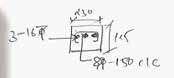
Issued to Contractor R0 1:50 @A2 Purpose Rev. Date SCALE: DRAWING NO DRAWING TITLE: DRAWN BY CHECKED BY REV NO PRINCIPAL DESIGN CONSULTANT MEP CONSULTANT STRUCTURAL CONSULTANT STAGE NAME STAMP NOTE: 1. All dimensions are in millimeters. All levels are in millimeters. This drawing copyright and property of the architect, is not to be produced, copied, handed over to third party or used for any other purpose other than for which intended. This drawing to be read and not to be scaled. All dimensions shall be verified on site prior to start of work any discrepancy shall be brought to the notice of the Architect. 6. The Contractor Project Manager must check all dimensions and details and be responsible for the same. Any discrepancy shall be notice of the Architect. 7. This drawing shall be read in conjunction with all relevant architectural, structural and services drawings. Any discrepancy noticed shall be brought to the attention of the consultants and resolved as soon as possible, but always prior to procurement execution of works. All the services ducts cut-outs are to be covered after services provisions. Drawing approval is for the conformity with outline design intent and does not relieve the contractor/ subcontractor from full responsibility for the accuracy, integration and fitness for purpose of design. 10. Construction Manager/Project Manager to revert back within 7 working days of receiving the drawings on coordination and buildability issues. If otherwise would be deemed that they have understood and accepted the drawing/design and own full responsibility for the works carried out accordingly. PROJECT: SITE: CLIENT: JAPAN SHAH CONSULTING ENGINEER 601, Sixth Floor, Silver Oaks Building, Near Mahalaxmi Cross Road, Paldi, Ahmedabad 380007 Mobile (direct): +91-94264 01793 Brick wall R.C.C. Dry wall Partiton Stone LEGEND Grass Blockwork Wardrobe Level Drop Gandhi Town House New Delhi UnBox Design Mr. Kovid Gandhi B-119, Ground Floor, East of Kailash, New Delhi 110065 Detail A 1 Detail - A : Plan 1:50 R = 1200 300 R = 1200 1500 300 1200 1200 5870 R = 1450 50 R = 1450 1450 3325 Cut-out in slab 4775 S4 Eboard wall as/interior detail x404 x403 1450 2 Front Elevation 1:50 3 Arch Side Elevation 1:50 00 +150 mm TOS STILT FRONT ROAD LVL -600 mm SER. ROAD Radius = 5190 Radius = 5190 1952 1455 Centre Point 8520 1200 5870 1450 +2850 TOS Ground Floor Lvl +5850 TOS First Floor Lvl +8850 TOS Second Floor Lvl 2700 750 3000 3000 4775 8535 01 -4940 -11940 -11940 -6900 x303 x404 ±00 -12265 -10000 -10000 -5140 -2800 +1500 1400 +1500 1740 R1 4 Section - 01 1:10 230 x 300mm R.C.C beam detail as/structure 115mm RCC toe wall detail as/structure MS flashing in approved paint fnish fixing as/vendor 18mm thk stone coping as/approved sample Glass railing section fixing as/vendor Metal framing for balcony false ceiling, detail as/vendor MS box section for front arch support Spec and fixing as/vendor Aluminum/Thermoash false ceiling as/approved sample Perforated fin detail as/vendor Linear Up-lighter detail as/vendor C/L MS Louvered railing detail as/elevation design MS plated fixed to stone to provide base for the front facade MS flashing in approved finish fixed to beam detail as/vendor MS plate fixed to beam to support facade screen, detail as/vendor 10mm tile balcony flooring over 40mm screeding as/approved sample 18mm thk stone skirting as/approved sample 18mm thk stone coping as/approved sample 100 40 200 100 Perforated Screen detail as/vendor Perforated Screen detail as/vendor 125 35 5 Section - 02 1:10 02 For Reference Metal Railing Details Ground Floor A-304.1 50 125 35mm MS Framed structure for front arch, detail as/vendor 125 35mm MS Framed structure for front arch, detail as/vendor 100 25 150 40 500 (as/site) 475 (as/site) SIDE PROFILE LIGHT DETAIL 1:60 @A3 SCALE: DRAWING TITLE: DRAWN BY VS CHECKED BY REV NO A377 DEFENCE COLONY New Delhi PRINCIPAL DESIGN CONSULTANT UnBox Design B-119, Ground Floor, East of Kailash, New Delhi 110065 STRUCTURAL CONSULTANT STAGE NAME STAMP NOTE: 1. All dimensions are in millimeters. 2. All levels are in millimeters. 3. This drawing is a copyright and property of the architect, is not to be produced, copied, handed over to third party or used for any other purpose other than for which is intended. 4. This drawing is to be read and not to be scaled. 5. All dimensions shall be verified on site prior to start of work any discrepancy shall be brought to the notice of the Architect. 6. The Contractor Project Manager must check all dimensions and details and be responsible for the same. Any discrepancy shall be notice of the Architect. 7. This drawing shall be read in conjunction with all relevant architectural, structural and services drawings. Any discrepancy noticed shall be brought to the attention of the consultants and resolved as soon as possible, but always prior to procurement execution of works. 8. All the services ducts cut-outs are to be covered after services provisions. 9. Drawing approval is for the conformity with outline design intent and does not relieve the contractor/ subcontractor from full responsibility for the accuracy, integration and fitness for purpose of design. 10. Construction Manager/Project Manager to revert back within 7 working days of receiving the drawings on coordination and buildability issues. otherwise it would be deemed that they have understood and accepted the drawing/design and own full responsibility for the works carried out accordingly. Brick wall R.C.C. Dry wall Partiton Stone LEGEND Grass Blockwork Wardrobe Level Drop R.C.C. For Review Purpose Rev. Date N 1050 1050 450 1050 1050 1050 450 1050 1050 1050 1050 450 1050 1 PLAN GF & FF 1:30 2 PLAN SF & TF 1:30 3 SECTION GF & FF 1:30 4 SECTION SF & TF 1:30 Section Section PROFILE LIGHT AS/SELECTION PROFILE LIGHT AS/SELECTION PROFILE LIGHT AS/SELECTION PROFILE LIGHT AS/SELECTION PROFILE LIGHT AS/SELECTION GLASS RAILING AS/SELECTION METAL RAILING AS/SELECTION PROFILE LIGHT AS/SELECTION PROFILE LIGHT AS/SELECTION OUTSIDE INSIDE OUTSIDE INSIDE OUTSIDE INSIDE OUTSIDE INSIDE OUTSIDE TERRACE 1052 450 212 65 SLOPE SLOPE SLOPE SLOPE
R1 1:50 @A2 Purpose Rev. Date SCALE: DRAWING NO DRAWING TITLE: DRAWN BY VS CHECKED BY AB REV NO PRINCIPAL DESIGN CONSULTANT MEP CONSULTANT STRUCTURAL CONSULTANT STAGE NAME STAMP NOTE: 1. All dimensions are in millimeters. All levels are in millimeters. This drawing copyright and property of the architect, is not to be produced, copied, handed over to third party or used for any other purpose other than for which intended. This drawing to be read and not to be scaled. All dimensions shall be verified on site prior to start of work any discrepancy shall be brought to the notice of the Architect. 6. The Contractor Project Manager must check all dimensions and details and be responsible for the same. Any discrepancy shall be notice of the Architect. 7. This drawing shall be read in conjunction with all relevant architectural, structural and services drawings. Any discrepancy noticed shall be brought to the attention of the consultants and resolved as soon as possible, but always prior to procurement execution of works. All the services ducts cut-outs are to be covered after services provisions. Drawing approval is for the conformity with outline design intent and does not relieve the contractor/ subcontractor from full responsibility for the accuracy, integration and fitness for purpose of design. 10. Construction Manager/Project Manager to revert back within 7 working days of receiving the drawings on coordination and buildability issues. If otherwise would be deemed that they have understood and accepted the drawing/design and own full responsibility for the works carried out accordingly. PROJECT: SITE: CLIENT: JAPAN SHAH CONSULTING ENGINEER 601, Sixth Floor, Silver Oaks Building, Near Mahalaxmi Cross Road, Paldi, Ahmedabad 380007 Mobile (direct): +91-94264 01793 Brick wall R.C.C. Dry wall Partiton Stone LEGEND Grass Blockwork Wardrobe Level Drop Gandhi Town House New Delhi UnBox Design Mr. Kovid Gandhi B-119, Ground Floor, East of Kailash, New Delhi 110065 Good for construction Third floor height inc. 1 Section - X 1:50 ± 00 +150 mm +2850 mm +5850 mm +8850 mm +11850mm +15865mm TOS- TERRACE TOS- SECOND FLOOR TOS- FIRST FLOOR TOS- GROUND FLOOR TOS STILT +18865mm TOS- MUMTY ROOF SERVICE ROAD LVL TOS- THIRD FLOOR -3850 mm TOS- BASEMENT 2700 3000 3000 3000 3850 Basement to stilt floor Floor to Floor Height: 4000mm No. of Riser 24 Riser Height 4000 24 = 166.6 mm No. of Treads 23 Tread Width 250mm Stilt to Ground Floor Floor to Floor Height: 2700mm No. of Riser 16 Riser Height 2700 16 = 168.75 mm No. of Treads 15 Tread Width 250mm Ground to First Floor Floor to Floor Height: 3000mm No. of Riser 18 Riser Height 3000 18 = 166.6 mm No. of Treads 17 Tread Width 250mm First to Second Floor Floor to Floor Height: 3000mm No. of Riser 18 Riser Height 3000 18 = 166.6 mm No. of Treads 17 Tread Width 250mm Second to Third Floor Floor to Floor Height: 3000mm No. of Riser 18 Riser Height 18 = 166.6 mm No. of Treads 17 Tread Width 250mm Third to Terrace Floor Floor to Floor Height: 4180mm No. of Riser 22 Riser Height 4180 = 190 mm No. of Treads 21 Tread Width 250mm -18 -17 -16 -15 -14 -13 -12 -11 -10 -09 -08 -07 -06 -05 -04 -03 -02 -01 00 01 02 03 04 05 06 07 08 09 10 12 13 14 15 16 16 17 18 19 20 21 22 23 24 25 26 27 28 29 30 31 32 33 34 34 35 36 37 38 39 40 41 42 43 44 45 46 47 48 49 50 51 52 52 53 54 55 56 57 58 59 60 61 62 63 64 65 66 67 68 69 70 70 71 72 73 74 75 76 77 78 79 80 81 82 83 84 85 86 87 88 00 101 201 301 401 501 601 701 1000 92 3000 4015 89 90 91 4180 2250 450 2550 450 2550 450 2550 450 3565 450 2550 450 300 4000 600 -18 -17 -16 -15 -14 -13 -12 -11 00 01 02 03 04 05 06 09 10 11 12 13 16 17 18 19 20 21 22 25 26 27 28 29 34 35 36 37 38 39 40 43 44 45 46 47 52 53 54 55 56 57 58 61 62 63 64 65 70 71 72 73 74 75 76 79 80 81 82 83 -09 08 24 42 60 78 101 201 301 401 501 601 701 2 Section - Y 1:50 ± 00 +150 mm +2850 mm +5850 mm +8850 mm +11850mm +15865mm TOS- TERRACE TOS- SECOND FLOOR TOS- FIRST FLOOR TOS- GROUND FLOOR TOS - STILT +18865mm TOS- MUMTY ROOF SERVICE ROAD LVL TOS- THIRD FLOOR -3850 mm TOS- BASEMENT 2700 3000 3000 3000 3850 3000 4015 2848 150 2534 150 2850 150 2850 150 5020 450 300 150 2228 600 84 85 86 92 Detail - 02 Detail 01 10mm Wall Finish 10mm Plaster Finish 230 mm Brick Wall 100mm Stone Skirting Floor Finish as/interior RCC Slab as/structure 100 3 Detail - 01 1:10 230 4 Detail - 02 1:20 190 190 190 79 80 81 78 82 83 Staircase Details A-402 Brickwork 150mm R.C.C Slab 190 380 570 50 150 3037 (As/site) 150 ± 00 +150 mm +2850 mm +5850 mm +8850 mm +11850 mm TOS- SECOND FLOOR TOS- FIRST FLOOR TOS- GROUND FLOOR TOS STILT FRONT ROAD LVL TOS- THIRD FLOOR -3900 mm TOS- BASEMENT -600 mm SER. ROAD -5400 mm TOS- LIFT PIT SCALE: DRAWING NO DRAWING TITLE: DRAWN BY VS CHECKED BY AB REV NO PROJECT: SITE: Gandhi Town House New Delhi PRINCIPAL DESIGN CONSULTANT UnBox Design CLIENT: STRUCTURAL CONSULTANT Mr. Kovid Gandhi STAGE NAME STAMP NOTE: 1. All dimensions are in millimeters. 2. All levels are in millimeters. 3. This drawing is a copyright and property of the architect, is not to be produced, copied, handed over to third party or used for any other purpose other than for which is intended. 4. This drawing is to be read and not to be scaled. 5. All dimensions shall be verified on site prior to start of work any discrepancy shall be brought to the notice of the Architect. 6. The Contractor Project Manager must check all dimensions and details and be responsible for the same. Any discrepancy shall be notice of the Architect. 7. This drawing shall be read in conjunction with all relevant architectural, structural and services drawings. Any discrepancy noticed shall be brought to the attention of the consultants and resolved as soon as possible, but always prior to procurement execution of works. 8. All the services ducts cut-outs are to be covered after services provisions. 9. Drawing approval is for the conformity with outline design intent and does not relieve the contractor/ subcontractor from full responsibility for the accuracy, integration and fitness for purpose of design. 10. Construction Manager/Project Manager to revert back within 7 working days of receiving the drawings on coordination and buildability issues. otherwise it would be deemed that they have understood and accepted the drawing/design and own full responsibility for the works carried out accordingly. JAPAN SHAH CONSULTING ENGINEER 601, Sixth Floor, Silver Oaks Building, Near Mahalaxmi Cross Road, Paldi, Ahmedabad 380007 Mobile (direct): +91-94264 01793 1:40 @A3 B-119, Ground Floor, East of Kailash, New Delhi 110065 Staircase - Plans Purpose Rev. Date A-406 R1 1500 1990 3850 150 2700 3000 3000 3000 4015 3000 15865 ± 00 +150 mm +2850 mm +5850 mm +8850 mm +11850 mm +15865mm TOS- TERRACE TOS- SECOND FLOOR TOS- FIRST FLOOR TOS- GROUND FLOOR TOS - STILT +18865mm TOS- MUMTY ROOF FRONT ROAD LVL TOS- THIRD FLOOR -3900 mm TOS- BASEMENT -600 mm SER. ROAD -5400 mm TOS- LIFT PIT 1500 3850 150 2700 3000 3000 3000 3000 15865 1670 565 100 500 865 540 R0 Issued on Site 13-07-2022 1 Section - YY' 1:40 2 Section - XX' 1:40 +15865mm TOS- TERRACE +18865m TOS- MUMTY ROOF 4015 5150 5150 R1 3rd floor ht. inc. 05-11-2022
SLOPE Washing Machine SLOPE w2 DOOR-WINDOW & WINDOW SCHEDULE 1:60 @A3 SCALE: DRAWING TITLE: DRAWN BY VS CHECKED BY REV NO A377 DEFENCE COLONY New Delhi PRINCIPAL DESIGN CONSULTANT UnBox Design B-119, Ground Floor, East of Kailash, New Delhi 110065 STRUCTURAL CONSULTANT STAGE NAME STAMP NOTE: 1. All dimensions are in millimeters. 2. All levels are in millimeters. 3. This drawing is a copyright and property of the architect, is not to be produced, copied, handed over to third party or used for any other purpose other than for which is intended. 4. This drawing is to be read and not to be scaled. 5. All dimensions shall be verified on site prior to start of work any discrepancy shall be brought to the notice of the Architect. 6. The Contractor Project Manager must check all dimensions and details and be responsible for the same. Any discrepancy shall be notice of the Architect. 7. This drawing shall be read in conjunction with all relevant architectural, structural and services drawings. Any discrepancy noticed shall be brought to the attention of the consultants and resolved as soon as possible, but always prior to procurement execution of works. 8. All the services ducts cut-outs are to be covered after services provisions. 9. Drawing approval is for the conformity with outline design intent and does not relieve the contractor/ subcontractor from full responsibility for the accuracy, integration and fitness for purpose of design. 10. Construction Manager/Project Manager to revert back within 7 working days of receiving the drawings on coordination and buildability issues. otherwise it would be deemed that they have understood and accepted the drawing/design and own full responsibility for the works carried out accordingly. Brick wall R.C.C. Dry wall Partiton Stone LEGEND Grass Blockwork Wardrobe Level Drop R.C.C. For Review Purpose Rev. Date N ±00 FFL Lvl ELEVATION ELEVATION ELEVATION ELEVATION ELEVATION PLAN PLAN W4 DW1 PLAN W6 PLAN W8 PLAN DW2 ±00 FFL Lvl Window No. S.No WINDOW SCHEDULE Remarks Rough opening Width x Height (mm) Room name & no. Window type Cill height from FFL (mm) Lintel height from FFL (mm) x202 Kitchen Retractable mesh Quantity Material x301 Bedroom 1 toilet 02 x303 01 03 x304 Bedroom 3 toilet 04 x302 Bedroom 1 02 x201 01 05 x305 Living and dinning STILT FLOOR GROUND FLOOR (As/art & glass) 06 07 x306 x307 Bedroom 3 Bedroom 2 DW1 DW1 W5 W6 W7 W8 DW2 01 01 01 01 01 01 01 2400 X 3200 600 X 2675 600 X 1200 600 X 1500 2400 X 1500 1900 X 2475 -75 -75 450 1200 900 900 -75 3125 (B.O.B.) No No No No No No No 08 x308 Bedroom 2 toilet W7 01 600 X 1950 450 No FIRST FLOOR Kitchen x401 Bedroom 1 toilet 02 x403 03 x404 Bedroom 3 toilet 04 x402 Bedroom 1 01 05 x405 Living and dinning 06 07 x406 x407 Bedroom 3 Bedroom 2 01 01 01 01 01 01 01 No No No No No No No 08 Bedroom 2 toilet 01 No x408 SECOND & THIRD FLOOR Kitchen x501, X601 Bedroom 1 toilet 02 x503, X 603 03 x504, X604 Bedroom 3 toilet 04 x502, X602 Bedroom 1 01 05 x505, X605 Living and dinning 06 07 x506, X606 x507, X607 Bedroom 3 Bedroom 2 01 01 01 01 01 01 01 No No No No No No No 08 Bedroom 2 toilet 01 No x508, X608 03 04 05 x203 x204 x205 Bathroom 1200 No 01 450 X 800 1200 No 01 450 X 800 W2 01 01 01 450 X 1000 750 750 750 2325 (B.O.B.) No No No Servant Room Servant Room Servant Room 3125 (B.O.B.) 3125 (B.O.B.) 2400 450 X 1000 450 X 1000 BASEMENT 01 x101 W1 01 560 X 1450 1200 2650 No Kitchen 06 x206 Toilet Staircase 560 X 700 W3 W3 W3 W4 W4 09 x309 01 1650 3125 (B.O.B.) Staircase 560 X 790 01 2335 No 09 x409 Staircase 01 No 09 x509, X609 Staircase 01 No 1750 2000 No W2 TERRACE x701 01 2400 Toilet 450 X 900 01 1500 No W2 2000 1750 1750 DW1 DW1 W5 W6 W7 W8 DW2 W7 W2 DW1 DW1 W5 W6 W7 W8 DW2 W7 W2 2400 X 3200 2400 2400 2400 2400 2400 X 3200 600 X 2675 600 X 1200 600 X 1500 2400 X 1500 1900 X 2475 -75 -75 450 1200 900 900 -75 3125 (B.O.B.) 600 X 1950 450 3125 (B.O.B.) 3125 (B.O.B.) 2400 3125 (B.O.B.) 560 X 790 2335 2400 X 3200 2400 2400 2400 2400 2400 X 3200 600 X 2675 600 X 1200 600 X 1500 2400 X 1500 1900 X 2475 -75 -75 450 1200 900 900 -75 3125 (B.O.B.) 600 X 1950 450 3125 (B.O.B.) 3125 (B.O.B.) 2400 3125 (B.O.B.) 560 X 790 2335 2400 X 3200 2400 2400 2400 2400 ELEVATION PLAN W3 ELEVATION PLAN W1 ELEVATION PLAN W2 ELEVATION PLAN W5 ELEVATION PLAN W7 560 VARIES 1200 560 VARIES 2335 450 1000 750 450 800 1200 2400 3125 3750 600 2675 450 600 1200 1200 600 1500 900 2400 1500 900 1900 3125 75 R0 A-501 DRAWING NO SCALE: DRAWING NO DRAWING TITLE: DRAWN BY AB CHECKED BY REV NO PROJECT: SITE: Gandhi Town House New Delhi PRINCIPAL DESIGN CONSULTANT UnBox Design CLIENT: STRUCTURAL CONSULTANT Mr. Kovid Gandhi STAGE NAME STAMP NOTE: 1. All dimensions are in millimeters. 2. All levels are in millimeters. 3. This drawing is a copyright and property of the architect, is not to be produced, copied, handed over to third party or used for any other purpose other than for which is intended. 4. This drawing is to be read and not to be scaled. 5. All dimensions shall be verified on site prior to start of work any discrepancy shall be brought to the notice of the Architect. 6. The Contractor Project Manager must check all dimensions and details and be responsible for the same. Any discrepancy shall be notice of the Architect. 7. This drawing shall be read in conjunction with all relevant architectural, structural and services drawings. Any discrepancy noticed shall be brought to the attention of the consultants and resolved as soon as possible, but always prior to procurement execution of works. 8. All the services ducts cut-outs are to be covered after services provisions. 9. Drawing approval is for the conformity with outline design intent and does not relieve the contractor/ subcontractor from full responsibility for the accuracy, integration and fitness for purpose of design. 10. Construction Manager/Project Manager to revert back within 7 working days of receiving the drawings on coordination and buildability issues. otherwise it would be deemed that they have understood and accepted the drawing/design and own full responsibility for the works carried out accordingly. JAPAN SHAH CONSULTING ENGINEER 601, Sixth Floor, Silver Oaks Building, Near Mahalaxmi Cross Road, Paldi, Ahmedabad 380007 Mobile (direct): +91-94264 01793 B-119, Ground Floor, East of Kailash, New Delhi 110065 1:50 @A3 Purpose Rev. Date A-502 ±00 FFL Lvl 750 650 900 800 1000 900 VARIES VARIES VARIES VARIES VARIES VARIES ELEVATION PLAN D1 PLAN D2 PLAN D3 F1 D1 D2 F3 D3 ELEVATION ELEVATION F2 75 75 75 Door No. Width x Height (mm) S.No. DOOR SCHEDULE 101 900 X 2400 01 02 Rough opening Room name & no. Width x Height (mm) Door Size Door Type Frame Material Frame Finish 102 BASEMENT STILT FLOOR 01 02 201 1000 x 2100 Pantry Quantity 01 01 01 03 01 750 x 2100 04 01 750 x 2100 Toilet 202 203 204 05 205 01 06 07 206 207 D2 D3 D2 Wood Wood Wood Wood Wood Wood Wood Wood Wood 01 01 01 800 X 2350 900 x 2050 800 X 2350 750 x 2100 750 x 2100 750 x 2100 750 x 2100 650 x 2050 650 x 2050 650 x 2050 650 x 2050 650 x 2050 650 x 2050 GROUND FLOOR 01 02 301 1000 x 3000 01 03 01 900 x 2400 04 01 750 x 2400 302 303 304 05 305 01 06 07 306 307 08 308 D3 Wood Wood Wood Wood Wood Wood Wood Wood 01 01 01 900 x 2950 01 1000 x 2400 D3 D2 1000 x 2400 900 x 2400 1000 x 2400 900 x 2400 900 x 2350 800 x 2350 650 x 2350 900 x 2350 800 x 2350 900 x 2350 800 x 2350 D1 D3 D2 D3 D2 09 309 Wood 01 1000 x 2400 900 x 2350 D3 FIRST FLOOR 01 02 401 01 03 01 04 01 402 403 404 05 405 01 06 07 406 407 08 408 Wood Wood Wood Wood Wood Wood Wood Wood 01 01 01 01 09 409 Wood 01 SECOND & THIRD FLOOR 01 02 501,601 01 03 01 04 01 502,602 503,603 504,604 05 505,605 01 06 07 506,606 507,607 08 508,608 D3 Wood Wood Wood Wood Wood Wood Wood Wood 01 01 01 01 D3 D2 D3 D2 D3 D3 D2 09 509,609 Wood 01 D3 TERRACE 01 701 Wood 01 900 x 2100 800 x 2050 D3 02 702 Wood 01 1000 X 2100 900 x 2050 D2 03 103 750 x 2400 01 Store D1 Wood 650 X 2350 900 X 2400 D1 D1 D1 D1 D1 D1 Stair Lobby Servant Room Servant Room Servant Room Servant Room Servant Toilet Servant Toilet Bedroom Toilet Stair & Lift Lobby Bedroom 1 Powder Room Bedroom 2 Bedroom 2 Toilet Bedroom 3 Bedroom 3 Toilet Kitchen D3 D3 D2 D1 D3 D2 D3 D2 D3 Bedroom Toilet Stair & Lift Lobby Bedroom 1 Powder Room Bedroom 2 Bedroom 2 Toilet Bedroom 3 Bedroom 3 Toilet Kitchen Bedroom Toilet Stair & Lift Lobby Bedroom 1 Bedroom 2 Bedroom 2 Toilet Bedroom 3 Bedroom 3 Toilet Kitchen Stair & Lift Lobby Toilet 10 310 Wood 01 1000 x 2400 900 x 2350 D3 Bedroom 2 Balcony 10 410 Wood 01 D3 Bedroom 2 Balcony 10 510,610 Bedroom 2 Balcony 01 Wood D3 1000 x 3000 900 x 2400 750 x 2400 900 x 2950 1000 x 2400 1000 x 2400 900 x 2400 1000 x 2400 900 x 2400 900 x 2350 800 x 2350 650 x 2350 900 x 2350 800 x 2350 900 x 2350 800 x 2350 1000 x 2400 900 x 2350 1000 x 2400 900 x 2350 1000 x 3000 900 x 2400 750 x 2400 900 x 2950 1000 x 2400 1000 x 2400 900 x 2400 1000 x 2400 900 x 2400 900 x 2350 800 x 2350 650 x 2350 900 x 2350 800 x 2350 900 x 2350 800 x 2350 1000 x 2400 900 x 2350 1000 x 2400 900 x 2350 DOOR SCHEDULE R0 125 230 3-16 mm 8 -150mmC/C Lintel detail for main doors (301, 401, 501, 601) 1 Sketch 1 1:10


DB SLOPE SLOPE JAAL EXTENDED 2FT AHEAD SLOPE SLOPE A B 01 03 04 05 02 J I H E F C D G SB and WALL LIGHT levels L1 L2 300 L3 600 900 Note All levels indicated in mm from FFL. L4 L5 L6 L7 L8 1050 1500 1800 2100 2400 L0 0 L9 1200 SB level from FFL to Bottom of Box Symbol Name Exhaust Fan Down Light Concealed Down Light One Direction Spot Light Wall Mounted Light 4' 3'/2' Fan Chandelier Pendant Light/Lamp Split AC Unit AC Casette Unit One Side Down Throw Ceiling Mounted Exhaust Fan Mirror Light LEGEND - LIGHT FIXTURES Ceiling Mounted Down Lighter Cupboard Light(Wire outlet) Directional Wall Washer Spot Cove Lighting Switch Board Uplighter Wall Washer CCTV Distribution box Panel Foot Light Room ROOM INDEX Stilt Floor Name Room size(mm) Stilt Parking Stair & Lift Lobby 201 202 203 204 205 206 3915 1390 Stair Lobby 1455 X 1540 Servant Toilet 2150 X 1350 Servant Room 1555 X 2200 Servant Room 2600 X 1570 RCP First Floor 1:60 @A3 SCALE: DRAWN BY VS CHECKED BY REV NO For Review Purpose Rev. Date R0 29-05-2023 For Review R1 29-06-2023 For Review R2 For Review 07-07-2023 STRUCTURAL CONSULTANT JAPAN SHAH CONSULTING ENGINEER 601, Sixth Floor, Silver Oaks Building, Near Mahalaxmi Cross Road, Paldi, Ahmedabad - 380007 DRAWING TITLE: A377 DEFENCE COLONY New Delhi PRINCIPAL DESIGN CONSULTANT UnBox Design B-119, Ground Floor, East of Kailash, New Delhi 110065 STAGE NAME STAMP NOTE: 1. All dimensions are in millimeters. 2. All levels are in millimeters. 3. This drawing is a copyright and property of the architect, is not to be produced, copied, handed over to third party or used for any other purpose other than for which is intended. 4. This drawing is to be read and not to be scaled. 5. All dimensions shall be verified on site prior to start of work any discrepancy shall be brought to the notice of the Architect. 6. The Contractor Project Manager must check all dimensions and details and be responsible for the same. Any discrepancy shall be notice of the Architect. 7. This drawing shall be read in conjunction with all relevant architectural, structural and services drawings. Any discrepancy noticed shall be brought to the attention of the consultants and resolved as soon as possible, but always prior to procurement / execution of works. 8. All the services ducts cut-outs are to be covered after services provisions. 9. Drawing approval is for the conformity with outline design intent and does not relieve the contractor/ subcontractor from full responsibility for the accuracy, integration and fitness for purpose of design. 10. Construction Manager/Project Manager to revert back within 7 working days of receiving the drawings on coordination and buildability issues. otherwise it would be deemed that they have understood and accepted the drawing/design and own full responsibility for the works carried out accordingly. Brick wall R.C.C. Dry wall Partiton Stone LEGEND Grass Blockwork Wardrobe Level Drop R.C.C. N 1 First Floor Lighting Layout 1:60 615 1055 230 1235 200 465 1055 995 995 795 790 1000 175 1250 1250 1250 1250 1255 720 eq eq 105 600 470 150 320 630 745 1610 1610 1610 1610 1235 700 810 200 2150 175 195 540 515 475 810 550 550 700 450 570 230 1880 230 730 870 490 510 515 695 745 465 230 1030 740 740 915 230 195 600 1420 450 450 175 1000 430 960 430 360 450 685 1640 1250 800 500 1250 1550 500 465 1170 1715 1715 285 620 620 515 920 575 255 700 255 300 330 330 300 300 480 480 185 295 300 eq eq 675 560 eq eq eq eq eq eq eq eq 540 810 115 515 130 400 600 515 750 850 3195 315 315 275 2150 225 515 515 765 315 315 1145 3645 810 700 375 1665 1180 1245 1600 870 605 805 805 920 1235 915 445 800 EQ EQ EQ EQ 1305 550 750 750 750 1085 925 570 770 770 775 1755 1755 300 300 300 300 300 300 765 300 730 360 PROFILE LIGHT PROFILE LIGHT PROFILE LIGHT 1 2 3 4 5 6 7 8 9 10 11 12 13 14 15 16 17 18 19 20 UP DN DB SLOPE SLOPE JAAL EXTENDED 2FT AHEAD SLOPE SLOPE SLOPE SLOPE A B 01 03 04 05 02 J I H E F C D G BELL SB-28 L2 SB-27 L1 SB-26 L2 SB-25 L2 SB-22 L3 SB-19 L1 SB-16 L2 SB-17 L1 SB-7 L5 SB-2 L3 SB-47 L9 SB-43 L3 SB-42 L5 SB-38 L1 SB-40 L2 SB-41 L2 SB-44 L1 SB-49 L7 SB-50 L4 SB-36 L2 SB-35 L2 SB-37 L6 SB-34 L5 SB-4 L2 SB-3 L5 SB-5 L2 SB-9 L2 SB-10 L2 SB-8 L5 SB-14 L2 SB-13 L2 SB-15 L6 SB-12 L5 SB-20 L5 SB-21 L3 SB-24 L5 SB-23 L5 SB-29 L5 SB-30 L1 SB-32 L2 SB-33 L2 SB-31 L6 SB-39 L1 SB-46 L4 SB-48 L4 CORRIDOR SB-1 L5 SB-2A L9 SB-15A L1 SB-8A L1 SB-18 L1 SB-22A L8 SB-11 L5 SB-51 L5 SB-16A L2 SB-22A L8 SB-45 L5 SB-21A L5 SB-48A L4 SB-6 L1 SB and WALL LIGHT levels L1 L2 300 L3 600 900 Note All levels indicated in mm from FFL. L4 L5 L6 L7 L8 1050 1500 1800 2100 2400 L0 0 L9 1200 SB level from FFL to Bottom of Box SB layout of First Floor 1:60 @A3 SCALE: DRAWN BY VS CHECKED BY REV NO For Review Purpose Rev. Date R0 29-05-2023 For Review R1 29-06-2023 For Review R2 For Review 07-07-2023 STRUCTURAL CONSULTANT JAPAN SHAH CONSULTING ENGINEER 601, Sixth Floor, Silver Oaks Building, Near Mahalaxmi Cross Road, Paldi, Ahmedabad - 380007 DRAWING TITLE: A377 DEFENCE COLONY New Delhi PRINCIPAL DESIGN CONSULTANT UnBox Design B-119, Ground Floor, East of Kailash, New Delhi 110065 STAGE NAME STAMP NOTE: 1. All dimensions are in millimeters. 2. All levels are in millimeters. 3. This drawing is a copyright and property of the architect, is not to be produced, copied, handed over to third party or used for any other purpose other than for which is intended. 4. This drawing is to be read and not to be scaled. 5. All dimensions shall be verified on site prior to start of work any discrepancy shall be brought to the notice of the Architect. 6. The Contractor Project Manager must check all dimensions and details and be responsible for the same. Any discrepancy shall be notice of the Architect. 7. This drawing shall be read in conjunction with all relevant architectural, structural and services drawings. Any discrepancy noticed shall be brought to the attention of the consultants and resolved as soon as possible, but always prior to procurement / execution of works. 8. All the services ducts cut-outs are to be covered after services provisions. 9. Drawing approval is for the conformity with outline design intent and does not relieve the contractor/ subcontractor from full responsibility for the accuracy, integration and fitness for purpose of design. 10. Construction Manager/Project Manager to revert back within 7 working days of receiving the drawings on coordination and buildability issues. otherwise it would be deemed that they have understood and accepted the drawing/design and own full responsibility for the works carried out accordingly. Brick wall R.C.C. Dry wall Partiton Stone LEGEND Grass Blockwork Wardrobe Level Drop R.C.C. N 1 First Floor SB Layout 1:60 400 250 500 500 1385 300 920 380 300 275 600 600 3200 1005 245 275 525 275 240 1300 450 580 915 300 935 610 300 860 1340 1650 390 390 400 290 230 1455 1435 1000 400 400 400 400 1665 400 400 275 1665 400 400 650 1360 220 175 195 250 275


DB SLOPE SLOPE JAAL EXTENDED 2FT AHEAD SLOPE SLOPE A B 01 03 04 05 02 J I H E F C D G BOFC BELL CORRIDOR SB-28 L2 SB-27 L1 SB-26 L2 SB-25 L2 SB-22 L3 SB-19 L1 SB-16 L2 SB-17 L1 SB-7 L5 SB-2 L3 SB-47 L9 SB-43 L3 SB-42 L5 SB-38 L1 SB-40 L2 SB-41 L2 SB-44 L1 SB-49 L7 SB-50 L4 SB-36 L2 SB-35 L2 SB-37 L6 SB-34 L5 SB-4 L2 SB-3 L5 SB-5 L2 SB-9 L2 SB-10 L2 SB-8 L5 SB-14 L2 SB-13 L2 SB-15 L6 SB-12 L5 SB-20 L5 SB-21 L3 SB-24 L5 SB-23 L5 SB-29 L5 SB-30 L1 SB-32 L2 SB-33 L2 SB-31 L6 SB-39 L1 SB-46 L4 SB-48 L4 SB-1 L5 SB-2A L9 SB-15A L1 SB-8A L1 SB-18 L1 SB-22A L8 SB-11 L5 SB-51 L5 SB-16A L2 SB-22A L8 SB-45 L5 SB-21A L5 SB-48A L4 SB-6 L1 Electrcial Looping First Floor 1:60 @A3 SCALE: DRAWN BY VS CHECKED BY REV NO For Review Purpose Rev. Date R0 29-05-2023 For Review R1 29-06-2023 For Review R2 For Review 07-07-2023 STRUCTURAL CONSULTANT JAPAN SHAH CONSULTING ENGINEER 601, Sixth Floor, Silver Oaks Building, Near Mahalaxmi Cross Road, Paldi, Ahmedabad - 380007 DRAWING TITLE: A377 DEFENCE COLONY New Delhi PRINCIPAL DESIGN CONSULTANT UnBox Design B-119, Ground Floor, East of Kailash, New Delhi 110065 STAGE NAME STAMP NOTE: 1. All dimensions are in millimeters. 2. All levels are in millimeters. 3. This drawing is a copyright and property of the architect, is not to be produced, copied, handed over to third party or used for any other purpose other than for which is intended. 4. This drawing is to be read and not to be scaled. 5. All dimensions shall be verified on site prior to start of work any discrepancy shall be brought to the notice of the Architect. 6. The Contractor Project Manager must check all dimensions and details and be responsible for the same. Any discrepancy shall be notice of the Architect. 7. This drawing shall be read in conjunction with all relevant architectural, structural and services drawings. Any discrepancy noticed shall be brought to the attention of the consultants and resolved as soon as possible, but always prior to procurement execution of works. 8. All the services ducts cut-outs are to be covered after services provisions. 9. Drawing approval is for the conformity with outline design intent and does not relieve the contractor/ subcontractor from full responsibility for the accuracy, integration and fitness for purpose of design. 10. Construction Manager/Project Manager to revert back within 7 working days of receiving the drawings on coordination and buildability issues. otherwise it would be deemed that they have understood and accepted the drawing/design and own full responsibility for the works carried out accordingly. Brick wall R.C.C. Dry wall Partiton Stone LEGEND Grass Blockwork Wardrobe Level Drop R.C.C. N 1 Electrcial Looping of First Floor 1:60 SB and WALL LIGHT levels L1 L2 300 L3 600 900 Note All levels indicated in mm from FFL. L4 L5 L6 L7 L8 1050 1500 1800 2100 2400 L0 0 L9 1200 SB level from FFL to Bottom of Box SB and WALL LIGHT levels L1 L2 300 L3 600 900 Note All levels indicated in mm from FFL. L4 L5 L6 L7 L8 1050 1500 1800 2100 2400 L0 L9 1200 SB level from FFL to Bottom of Box Symbol Name Exhaust Fan Down Light Concealed Down Light One Direction Spot Light Wall Mounted Light 4' 3'/2' Fan Chandelier Pendant Light/Lamp Split AC Unit AC Casette Unit One Side Down Throw Ceiling Mounted Exhaust Fan Mirror Light LEGEND LIGHT FIXTURES Ceiling Mounted Down Lighter Cupboard Light(Wire outlet) Directional Wall Washer Spot Cove Lighting Switch Board Uplighter Wall Washer CCTV DB Distribution box Panel Foot Light NOTE SB-04 SB-11 SB-24 SB-25 SB-34 SB-40 contains two way switch which are provision kept for cove light in false ceiling S.No. DESCRIPTION SWITCH BOARD DETAILS MODULE SB-1 SB-21 SB-19 SB-20 SB-22 SB-23 SB-24 SB-2 SB-3 SB-4 SB-5 SB-6 SB-7 SB-8 SB-9 SB-10 SB-11 SB-12 SB-25 SB-14 SB-15 SB-16 SB-17 SB-26 SB-27 SB-28 SB-29 SB-30 SB-18 SB-31 SB-32 SB-33 SB-34 SB-35 SB-36 SB-37 SB-38 SB-39 SB-40 SB-41 SB-42 SB-13 SB-43 SB-44 SB-45 SB-46 4 6 6+2 3 4 4 6+2 6 6 6 M 6 6 6 3 4 6 6 6 6 6+2 3 3 4 6 3 3 3 6 6 SB-47 SB-48 SB-49 SB-50 2 6 3 6 M 6 6+2 6 6 chimney 4 6+2 6 4 6+2 6 4 6+2 6 SB-2A 3 SB-8A 4 SB-15A 4 SB-22A gyser 3 SB-21A M M 6+2 6+2 6+2 gyser SB-48A profile 4 6 gyser gyser SB-51 4 PROFILE LIGHT PROFILE LIGHT PROFILE LIGHT DB SLOPE SLOPE JAAL EXTENDED 2FT AHEAD SLOPE SLOPE A B 01 03 04 05 02 J I H E F C D G BOFC +3100 +3500 BOS +3150 +3500 BOS +3150 BOFC +3100 BOFC +3100 BOFC +3500 BOS +3150 BOFC +3150 BOFC +3100 BOFC +3150 BOFC 3100 BOFC +3150 BOFC BOFC +3150 BOFC +3150 BOFC +3150 BOFC +3150 BOFC +3150 BOFC +3500 BOS SB and WALL LIGHT levels L1 L2 300 L3 600 900 Note All levels indicated in mm from FFL. L4 L5 L6 L7 L8 1050 1500 1800 2100 2400 L0 0 L9 1200 SB level from FFL to Bottom of Box Ceiling Finish First Floor 1:60 @A3 SCALE: DRAWN BY VS CHECKED BY REV NO For Review Purpose Rev. Date R0 29-05-2023 For Review R1 29-06-2023 For Review R2 For Review 07-07-2023 STRUCTURAL CONSULTANT JAPAN SHAH CONSULTING ENGINEER 601, Sixth Floor, Silver Oaks Building, Near Mahalaxmi Cross Road, Paldi, Ahmedabad - 380007 DRAWING TITLE: A377 DEFENCE COLONY New Delhi PRINCIPAL DESIGN CONSULTANT UnBox Design B-119, Ground Floor, East of Kailash, New Delhi 110065 STAGE NAME STAMP NOTE: 1. All dimensions are in millimeters. 2. All levels are in millimeters. 3. This drawing is a copyright and property of the architect, is not to be produced, copied, handed over to third party or used for any other purpose other than for which is intended. 4. This drawing is to be read and not to be scaled. 5. All dimensions shall be verified on site prior to start of work any discrepancy shall be brought to the notice of the Architect. 6. The Contractor Project Manager must check all dimensions and details and be responsible for the same. Any discrepancy shall be notice of the Architect. 7. This drawing shall be read in conjunction with all relevant architectural, structural and services drawings. Any discrepancy noticed shall be brought to the attention of the consultants and resolved as soon as possible, but always prior to procurement execution of works. 8. All the services ducts cut-outs are to be covered after services provisions. 9. Drawing approval is for the conformity with outline design intent and does not relieve the contractor/ subcontractor from full responsibility for the accuracy, integration and fitness for purpose of design. 10. Construction Manager/Project Manager to revert back within 7 working days of receiving the drawings on coordination and buildability issues. otherwise it would be deemed that they have understood and accepted the drawing/design and own full responsibility for the works carried out accordingly. Brick wall R.C.C. Dry wall Partiton Stone LEGEND Grass Blockwork Wardrobe Level Drop R.C.C. N 1 Ceiling Finish Plan First Floor 1:60 Symbol Name Exhaust Fan Down Light Concealed Down Light One Direction Spot Light Wall Mounted Light 4' 3'/2' Fan Chandelier Pendant Light/Lamp Split AC Unit AC Casette Unit One Side Down Throw Ceiling Mounted Exhaust Fan Mirror Light LEGEND LIGHT FIXTURES Ceiling Mounted Down Lighter Cupboard Light(Wire outlet) Directional Wall Washer Spot Cove Lighting Switch Board Uplighter Wall Washer CCTV DB Distribution box Panel Foot Light 400 400 400 600 200 BEAM LINE BEAM LINE BEAM LINE BEAM LINE 400 400 400 400 400 400 1350 400 600 BEAM LINE BEAM LINE BEAM LINE BEAM LINE BEAM LINE BEAM LINE 200 400 400 400 400 400 680 400 400 680 950 400 950 400 400 400 960 960 600 200 200 2800 185 300 2935 185 300 2800 185 300 115 115 100mm left for curtain 100mm left for curtain
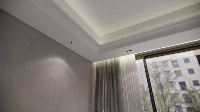
12mm thk. POP False celing 15mm Plaster R.C.C Beam 3 Section D - Typical Pelmet Detail For Bedrooms 1:5 Curtain track Ceiling Line In Elevation +3150 B.O.F.C +3500 B.O.S 12mm thk. POP False celing Cove Light Aluminium frame Aluminium Frame 150mm thk. slab +3500 B.O.S 1:5 @A3 SCALE: DRAWN BY VS CHECKED BY REV NO For Review Purpose Rev. Date R0 For Review 07-07-2023 STRUCTURAL CONSULTANT JAPAN SHAH CONSULTING ENGINEER 601, Sixth Floor, Silver Oaks Building, Near Mahalaxmi Cross Road, Paldi, Ahmedabad - 380007 DRAWING TITLE: A377 DEFENCE COLONY New Delhi PRINCIPAL DESIGN CONSULTANT UnBox Design B-119, Ground Floor, East of Kailash, New Delhi 110065 STAGE NAME STAMP NOTE: 1. All dimensions are in millimeters. 2. All levels are in millimeters. 3. This drawing is a copyright and property of the architect, is not to be produced, copied, handed over to third party or used for any other purpose other than for which is intended. 4. This drawing is to be read and not to be scaled. 5. All dimensions shall be verified on site prior to start of work any discrepancy shall be brought to the notice of the Architect. 6. The Contractor Project Manager must check all dimensions and details and be responsible for the same. Any discrepancy shall be notice of the Architect. 7. This drawing shall be read in conjunction with all relevant architectural, structural and services drawings. Any discrepancy noticed shall be brought to the attention of the consultants and resolved as soon as possible, but always prior to procurement execution of works. 8. All the services ducts cut-outs are to be covered after services provisions. 9. Drawing approval is for the conformity with outline design intent and does not relieve the contractor/ subcontractor from full responsibility for the accuracy, integration and fitness for purpose of design. 10. Construction Manager/Project Manager to revert back within 7 working days of receiving the drawings on coordination and buildability issues. otherwise it would be deemed that they have understood and accepted the drawing/design and own full responsibility for the works carried out accordingly. Brick wall R.C.C. Dry wall Partiton Stone LEGEND Grass Blockwork Wardrobe Level Drop R.C.C. N RCP - Typical Floor Section Details Cove Light 2 Section C - Typical False Ceiling Detail In Bedrooms 1:5 150mm thk slab Cove Light Curtain track Pelmet R.C.C Beam 150mm thk slab 200 115 300 300 400 +3200 B.O.B 10 325 eq eq Pelmet R.C.C Beam +3150 B.O.F.C +3500 B.O.S 15mm Plaster 1 Section B - Typical False Cieling Detail in Lobby 1:5 Aluminium Frame 12 mm thk. P.O.P. False Ceiling 12 mm thk. P.O.P. False Ceiling R.C.C Beam 150mm thk slab Aluminium Frame +3150 B.O.F.C +3200 B.O.B +3200 B.O.B 40 25 100 100 350 eq eq R.C.C Beam +3150 B.O.F.C +3500 B.O.S 1 Section A - Typical False Ceiling Detail In Living Room 1:5 +3200 B.O.B. Cove Light Aluminium Frame 1:5 @A3 SCALE: DRAWN BY VS CHECKED BY REV NO For Review Purpose Rev. Date R0 For Review STRUCTURAL CONSULTANT JAPAN SHAH CONSULTING ENGINEER 601, Sixth Floor, Silver Oaks Building, Near Mahalaxmi Cross Road, Paldi, Ahmedabad - 380007 DRAWING TITLE: A377 DEFENCE COLONY New Delhi PRINCIPAL DESIGN CONSULTANT UnBox Design B-119, Ground Floor, East of Kailash, New Delhi 110065 STAGE NAME STAMP NOTE: 1. All dimensions are in millimeters. 2. All levels are in millimeters. 3. This drawing is a copyright and property of the architect, is not to be produced, copied, handed over to third party or used for any other purpose other than for which is intended. 4. This drawing is to be read and not to be scaled. 5. All dimensions shall be verified on site prior to start of work any discrepancy shall be brought to the notice of the Architect. 6. The Contractor Project Manager must check all dimensions and details and be responsible for the same. Any discrepancy shall be notice of the Architect. 7. This drawing shall be read in conjunction with all relevant architectural, structural and services drawings. Any discrepancy noticed shall be brought to the attention of the consultants and resolved as soon as possible, but always prior to procurement execution of works. 8. All the services ducts cut-outs are to be covered after services provisions. 9. Drawing approval is for the conformity with outline design intent and does not relieve the contractor/ subcontractor from full responsibility for the accuracy, integration and fitness for purpose of design. 10. Construction Manager/Project Manager to revert back within 7 working days of receiving the drawings on coordination and buildability issues. otherwise it would be deemed that they have understood and accepted the drawing/design and own full responsibility for the works carried out accordingly. Brick wall R.C.C. Dry wall Partiton Stone LEGEND Grass Blockwork Wardrobe Level Drop R.C.C. N RCP - Typical Floor Section Details 07-07-2023 15mm Plaster 150mm thk slab R.C.C Beam 2 Section D - Pelmet Detail For Living Room 1:5 150mm thk. slab +3500 B.O.S +3150 B.O.F.C +3200 B.O.B. Pelmet 12mm thk. POP False celing Aluminium frame 15mm Plaster Curtain track Cove Light R-100 R-100 40 25 3 3D VIEW OF LIVING ROOM FALSE CEILING
-1 -2 -3 -4 -5 -6 -7 -8 -9 -11 DN UGT 1 1665 X 1550 UGT 2 1665 X 1550 UGT 3 1665 X 1550 UGT 4 1665 X 1550 UGT5 1665 X 1550 -12 -13 -14 -15 -16 -17 -18 -19 -20 -21 -10 -22 -23 A B 01 03 04 05 02 J I H E F C D G DB G BASEMENT WATER SUPPLY PLAN For Review 1:60 @A3 SCALE: DRAWN BY VS CHECKED BY REV NO Purpose Rev. Date STRUCTURAL CONSULTANT JAPAN SHAH CONSULTING ENGINEER 601, Sixth Floor, Silver Oaks Building, Near Mahalaxmi Cross Road, Paldi, Ahmedabad - 380007 DRAWING TITLE: A377 DEFENCE COLONY New Delhi PRINCIPAL DESIGN CONSULTANT UnBox Design B-119, Ground Floor, East of Kailash, New Delhi 110065 STAGE NAME STAMP NOTE: 1. All dimensions are in millimeters. 2. All levels are in millimeters. 3. This drawing is a copyright and property of the architect, is not to be produced, copied, handed over to third party or used for any other purpose other than for which is intended. 4. This drawing is to be read and not to be scaled. 5. All dimensions shall be verified on site prior to start of work any discrepancy shall be brought to the notice of the Architect. 6. The Contractor Project Manager must check all dimensions and details and be responsible for the same. Any discrepancy shall be notice of the Architect. 7. This drawing shall be read in conjunction with all relevant architectural, structural and services drawings. Any discrepancy noticed shall be brought to the attention of the consultants and resolved as soon as possible, but always prior to procurement execution of works. 8. All the services ducts cut-outs are to be covered after services provisions. 9. Drawing approval is for the conformity with outline design intent and does not relieve the contractor/ subcontractor from full responsibility for the accuracy, integration and fitness for purpose of design. 10. Construction Manager/Project Manager to revert back within 7 working days of receiving the drawings on coordination and buildability issues. otherwise it would be deemed that they have understood and accepted the drawing/design and own full responsibility for the works carried out accordingly. Brick wall R.C.C. Dry wall Partiton Stone LEGEND Grass Blockwork Wardrobe Level Drop R.C.C. N RW CUTOUT B.O.CUTOUT -500 FROM ±00 SIZE (800 X 230) RW CUTOUT B.O.CUTOUT = -350 FROM ±00 SIZE (800 X 230) RW CUTOUT B.O.CUTOUT = -350 FROM = ±00 SIZE (800 X 230) 20Ø DWS 20Ø DWS 15Ø DWS 15Ø DWS 15Ø DWS SUMP PIT 5# 25Ø MUNICIPAL LINE FROM WATER METER AT STILT FLOOR 5# 25Ø MUNICIPAL LINE TO WATER METER AT STILT FLOOR LEGEND: 110 OD uPVC SOIL PIPE DOM. WATER FOR 3rd FLOOR DOM. WATER FOR 2nd FLOOR DOM. WATER FOR 1st FLOOR DOM. WATER RISER FOR 4th.FLOOR DOM. WATER RISER FOR 3rd FLOOR DOM. WATER RISER FOR 2nd FLOOR DOM. WATER RISER FOR 1st FLOOR 10 DOM. WATER FOR STILT & BASEMENT FLOOR 11 BORE WELL RISER 12 110 OD PVC RAIN WATER PIPE R 110 OD uPVC Waste Water PIPE 13 DOM. WATER RISER FOR STILT & BASEMENT DOM. WATER FOR GROUND FLOOR 25Ø DWS 590 335 520 555 720 1100 R1 Issued on site 30-06-2023 R0 Issued on site 06-05-2023 P-102.1 R1 DRAWING NO 2 4 10 11 12 13 14 15 16 17 18 19 20 UP DN DB Washing Machine SLOPE SLOPE SLOPE SLOPE JAAL EXTENDED 2FT AHEAD SLOPE SLOPE G G G G GROUND FLOOR WATER SUPPLY PLAN For Review 1:60 @A3 SCALE: DRAWN BY VS CHECKED BY REV NO Purpose Rev. Date STRUCTURAL CONSULTANT JAPAN SHAH CONSULTING ENGINEER 601, Sixth Floor, Silver Oaks Building, Near Mahalaxmi Cross Road, Paldi, Ahmedabad - 380007 DRAWING TITLE: A377 DEFENCE COLONY New Delhi PRINCIPAL DESIGN CONSULTANT UnBox Design B-119, Ground Floor, East of Kailash, New Delhi 110065 STAGE NAME STAMP NOTE: 1. All dimensions are in millimeters. 2. All levels are in millimeters. 3. This drawing is a copyright and property of the architect, is not to be produced, copied, handed over to third party or used for any other purpose other than for which is intended. 4. This drawing is to be read and not to be scaled. 5. All dimensions shall be verified on site prior to start of work any discrepancy shall be brought to the notice of the Architect. 6. The Contractor Project Manager must check all dimensions and details and be responsible for the same. Any discrepancy shall be notice of the Architect. 7. This drawing shall be read in conjunction with all relevant architectural, structural and services drawings. Any discrepancy noticed shall be brought to the attention of the consultants and resolved as soon as possible, but always prior to procurement execution of works. 8. All the services ducts cut-outs are to be covered after services provisions. 9. Drawing approval is for the conformity with outline design intent and does not relieve the contractor/ subcontractor from full responsibility for the accuracy, integration and fitness for purpose of design. 10. Construction Manager/Project Manager to revert back within 7 working days of receiving the drawings on coordination and buildability issues. otherwise it would be deemed that they have understood and accepted the drawing/design and own full responsibility for the works carried out accordingly. Brick wall R.C.C. Dry wall Partiton Stone LEGEND Grass Blockwork Wardrobe Level Drop R.C.C. N LEGEND: 110 OD uPVC SOIL PIPE DOM. WATER FOR 3rd FLOOR DOM. WATER FOR 2nd FLOOR DOM. WATER FOR 1st FLOOR DOM. WATER RISER FOR 4th.FLOOR DOM. WATER RISER FOR 3rd FLOOR DOM. WATER RISER FOR 2nd FLOOR DOM. WATER RISER FOR 1st FLOOR 10 DOM. WATER FOR STILT & BASEMENT FLOOR 11 BORE WELL RISER 12 110 OD PVC RAIN WATER PIPE R 110 OD uPVC Waste Water PIPE 13 DOM. WATER RISER FOR STILT & BASEMENT DOM. WATER FOR GROUND FLOOR 610 610 630 350 280 115 840 575 2460 1345 720 1020 330 1120 1965 1055 350 510 700 2090 660 350 405 640 480 15Ø DWS 15Ø DWS 20Ø DWS 15Ø HWS 15Ø DWS 15Ø DWS 15Ø HWS 15Ø DWS 15Ø HWS 15Ø DWS 15Ø DWS 15Ø HWS 15Ø DWS 15Ø DWS 15Ø HWS 20Ø HWS 20Ø DWS 15Ø DWS 20Ø DWS 15Ø HWS 15Ø HWS 15Ø DWS 20Ø HWS 20Ø DWS 20Ø DWS 15Ø HWS 20Ø DWS R1 Issued on site 30-06-2023 R0 Issued on site 06-05-2023 P-102.3 R1 DRAWING NO
4 10 11 12 13 14 15 16 17 18 19 20 UP DN A B 01 03 04 05 02 J I H E F C D G DB SLOPE SLOPE SLOPE SLOPE SLOPE SLOPE SLOPE SLOPE SLOPE SLOPE SLOPE SLOPE TERRACE WATER SUPPLY PLAN For Review 1:60 @A3 SCALE: DRAWN BY VS CHECKED BY REV NO STRUCTURAL CONSULTANT JAPAN SHAH CONSULTING ENGINEER 601, Sixth Floor, Silver Oaks Building, Near Mahalaxmi Cross Road, Paldi, Ahmedabad - 380007 DRAWING TITLE: A377 DEFENCE COLONY New Delhi PRINCIPAL DESIGN CONSULTANT UnBox Design B-119, Ground Floor, East of Kailash, New Delhi 110065 STAGE NAME STAMP NOTE: 1. All dimensions are in millimeters. 2. All levels are in millimeters. 3. This drawing is a copyright and property of the architect, is not to be produced, copied, handed over to third party or used for any other purpose other than for which is intended. 4. This drawing is to be read and not to be scaled. 5. All dimensions shall be verified on site prior to start of work any discrepancy shall be brought to the notice of the Architect. 6. The Contractor Project Manager must check all dimensions and details and be responsible for the same. Any discrepancy shall be notice of the Architect. 7. This drawing shall be read in conjunction with all relevant architectural, structural and services drawings. Any discrepancy noticed shall be brought to the attention of the consultants and resolved as soon as possible, but always prior to procurement / execution of works. 8. All the services ducts cut-outs are to be covered after services provisions. 9. Drawing approval is for the conformity with outline design intent and does not relieve the contractor/ subcontractor from full responsibility for the accuracy, integration and fitness for purpose of design. 10. Construction Manager/Project Manager to revert back within 7 working days of receiving the drawings on coordination and buildability issues. otherwise it would be deemed that they have understood and accepted the drawing/design and own full responsibility for the works carried out accordingly. Brick wall R.C.C. Dry wall Partiton Stone LEGEND Grass Blockwork Wardrobe Level Drop R.C.C. N 20Ø DWS 20Ø DWS 25Ø DWS 20Ø DWS 20Ø DWS 20Ø DWS LEGEND: 110 OD uPVC SOIL PIPE DOM. WATER FOR 3rd FLOOR DOM. WATER FOR 2nd FLOOR DOM. WATER FOR 1st FLOOR DOM. WATER RISER FOR 4th.FLOOR DOM. WATER RISER FOR 3rd FLOOR DOM. WATER RISER FOR 2nd FLOOR DOM. WATER RISER FOR 1st FLOOR 10 DOM. WATER FOR STILT & BASEMENT FLOOR 11 BORE WELL RISER 12 110 OD PVC RAIN WATER PIPE R 110 OD uPVC Waste Water PIPE 13 DOM. WATER RISER FOR STILT & BASEMENT DOM. WATER FOR GROUND FLOOR 15Ø DWS 15Ø DWS 15Ø DWS 20Ø DWS 815 350 470 820 820 20Ø DWS Purpose Rev. Date R1 Issued on site 30-06-2023 R0 Issued on site 06-05-2023 P-102.7 R1 DRAWING NO DB FT FT BASEMENT DRAINAGE PLAN 1:60 @A3 SCALE: DRAWN BY VS CHECKED BY REV NO Purpose Rev. Date STRUCTURAL CONSULTANT JAPAN SHAH CONSULTING ENGINEER 601, Sixth Floor, Silver Oaks Building, Near Mahalaxmi Cross Road, Paldi, Ahmedabad - 380007 DRAWING TITLE: A377 DEFENCE COLONY New Delhi PRINCIPAL DESIGN CONSULTANT UnBox Design B-119, Ground Floor, East of Kailash, New Delhi 110065 STAGE NAME STAMP NOTE: 1. All dimensions are in millimeters. 2. All levels are in millimeters. 3. This drawing is a copyright and property of the architect, is not to be produced, copied, handed over to third party or used for any other purpose other than for which is intended. 4. This drawing is to be read and not to be scaled. 5. All dimensions shall be verified on site prior to start of work any discrepancy shall be brought to the notice of the Architect. 6. The Contractor Project Manager must check all dimensions and details and be responsible for the same. Any discrepancy shall be notice of the Architect. 7. This drawing shall be read in conjunction with all relevant architectural, structural and services drawings. Any discrepancy noticed shall be brought to the attention of the consultants and resolved as soon as possible, but always prior to procurement / execution of works. 8. All the services ducts cut-outs are to be covered after services provisions. 9. Drawing approval is for the conformity with outline design intent and does not relieve the contractor/ subcontractor from full responsibility for the accuracy, integration and fitness for purpose of design. 10. Construction Manager/Project Manager to revert back within 7 working days of receiving the drawings on coordination and buildability issues. otherwise it would be deemed that they have understood and accepted the drawing/design and own full responsibility for the works carried out accordingly. Brick wall R.C.C. Dry wall Partiton Stone LEGEND Grass Blockwork Wardrobe Level Drop R.C.C. N DRAWING NO P-101.2 C/L C/L C/L C/L C/L C/L C/L 50Ø G.I. SUMP RISER PIPE SUMP PIT 1365x1520 MM Depth 1500 MM WASTE PIPE Ø110MM OD uPVC SLOPE 1 :100 110MM WIDE SLEEVES 110MM WIDE SLEEVES MANHOLE SOIL PIPE Ø110MM OD uPVC SLOPE :100 WASTE WATER PIPE Ø110MM OD uPVC SLOPE 1 :100 WASTE WATER PIPE Ø110MM OD uPVC SLOPE :100 1 DETAIL 1 1:30 SUMP SECTION 1 SUMP SECTION 1:30 Ø110MM WIDE SLEEVES LEGEND: 110 OD uPVC SOIL PIPE 110 OD uPVC Waste Water PIPE 110 OD uPVC PIPE 600x600mm SUMP SECTION F.D. F.T. F.T. Good For Construction R1 1170 588 850 835 600 900 600 100 1500 100 468 Ø110MM OD uPVC WASTE WATER PIPE Ø110MM OD uPVC SOIL PIPE
9 10 11 12 13 14 15 16 17 18 UP DN DN -1 -2 -3 -4 -5 -6 -7 -8 -9 -10 -11 -12 A B 01 03 04 05 02 J H E F C D G DB STILT DRAINAGE PLAN For Review 1:60 @A3 SCALE: DRAWN BY VS CHECKED BY REV NO Purpose Rev. Date STRUCTURAL CONSULTANT JAPAN SHAH CONSULTING ENGINEER 601, Sixth Floor, Silver Oaks Building, Near Mahalaxmi Cross Road, Paldi, Ahmedabad - 380007 DRAWING TITLE: A377 DEFENCE COLONY New Delhi PRINCIPAL DESIGN CONSULTANT UnBox Design B-119, Ground Floor, East of Kailash, New Delhi 110065 STAGE NAME STAMP NOTE: 1. All dimensions are in millimeters. 2. All levels are in millimeters. 3. This drawing is a copyright and property of the architect, is not to be produced, copied, handed over to third party or used for any other purpose other than for which is intended. 4. This drawing is to be read and not to be scaled. 5. All dimensions shall be verified on site prior to start of work any discrepancy shall be brought to the notice of the Architect. 6. The Contractor Project Manager must check all dimensions and details and be responsible for the same. Any discrepancy shall be notice of the Architect. 7. This drawing shall be read in conjunction with all relevant architectural, structural and services drawings. Any discrepancy noticed shall be brought to the attention of the consultants and resolved as soon as possible, but always prior to procurement execution of works. 8. All the services ducts cut-outs are to be covered after services provisions. 9. Drawing approval is for the conformity with outline design intent and does not relieve the contractor/ subcontractor from full responsibility for the accuracy, integration and fitness for purpose of design. 10. Construction Manager/Project Manager to revert back within 7 working days of receiving the drawings on coordination and buildability issues. otherwise it would be deemed that they have understood and accepted the drawing/design and own full responsibility for the works carried out accordingly. Brick wall R.C.C. Dry wall Partiton Stone LEGEND Grass Blockwork Wardrobe Level Drop R.C.C. N 600 X 600 MM INSPECTION CHAMBER 600 X 600 MM INSPECTION CHAMBER I.C. I.C. I.C. I.C. Ø110MM OD uPVC PIPE Ø110MM OD uPVC PIPE Ø110MM OD uPVC SOIL PIPE Ø110MM OD uPVC WASTE WATER PIPE Ø110MM OD uPVC SOIL PIPE Ø110MM OD uPVC WASTE WATER PIPE Ø110MM OD uPVC SOIL PIPE FROM STILT ROOF Ø110MM OD uPVC WASTE WATER PIPE FROM STILT ROOF Ø110MM OD uPVC SOIL PIPE Ø110MM OD uPVC WASTE WATER PIPE Ø110MM OD uPVC PIPE Ø110MM OD uPVC PIPE 460 540 750 350 150 290 150 520 750 750 750 750 450 450 1190 6594 450 340 LEGEND: 110 OD uPVC SOIL PIPE DOM. WATER FOR 3rd FLOOR DOM. WATER FOR 2nd FLOOR DOM. WATER FOR 1st FLOOR DOM. WATER RISER FOR 4th.FLOOR DOM. WATER RISER FOR 3rd FLOOR DOM. WATER RISER FOR 2nd FLOOR DOM. WATER RISER FOR 1st FLOOR 10 DOM. WATER FOR STILT & BASEMENT FLOOR 11 BORE WELL RISER 12 110 OD PVC RAIN WATER PIPE R 110 OD uPVC Waste Water PIPE 13 DOM. WATER RISER FOR STILT & BASEMENT DOM. WATER FOR GROUND FLOOR I.C. Ø110MM OD uPVC WASTE WATER PIPE Ø110MM RAIN WATER PIPE TO MUNICIPAL DRAIN Ø110MM RAIN WATER PIPE TO MUNICIPAL DRAIN Ø110MM RAIN WATER PIPE TO MUNICIPAL DRAIN R1 Issued on site 30-06-2023 R0 Issued on site 06-05-2023 P-101.3 R1 DRAWING NO 10 11 12 13 14 15 16 17 18 19 20 UP DN DB SLOPE SLOPE SLOPE SLOPE JAAL EXTENDED 2FT AHEAD SLOPE SLOPE GROUND FLOOR DRAINAGE PLAN For Review 1:60 @A3 SCALE: DRAWN BY VS CHECKED BY REV NO Purpose Rev. Date STRUCTURAL CONSULTANT JAPAN SHAH CONSULTING ENGINEER 601, Sixth Floor, Silver Oaks Building, Near Mahalaxmi Cross Road, Paldi, Ahmedabad - 380007 DRAWING TITLE: A377 DEFENCE COLONY New Delhi PRINCIPAL DESIGN CONSULTANT UnBox Design B-119, Ground Floor, East of Kailash, New Delhi 110065 STAGE NAME STAMP NOTE: 1. All dimensions are in millimeters. 2. All levels are in millimeters. 3. This drawing is a copyright and property of the architect, is not to be produced, copied, handed over to third party or used for any other purpose other than for which is intended. 4. This drawing is to be read and not to be scaled. 5. All dimensions shall be verified on site prior to start of work any discrepancy shall be brought to the notice of the Architect. 6. The Contractor Project Manager must check all dimensions and details and be responsible for the same. Any discrepancy shall be notice of the Architect. 7. This drawing shall be read in conjunction with all relevant architectural, structural and services drawings. Any discrepancy noticed shall be brought to the attention of the consultants and resolved as soon as possible, but always prior to procurement execution of works. 8. All the services ducts cut-outs are to be covered after services provisions. 9. Drawing approval is for the conformity with outline design intent and does not relieve the contractor/ subcontractor from full responsibility for the accuracy, integration and fitness for purpose of design. 10. Construction Manager/Project Manager to revert back within 7 working days of receiving the drawings on coordination and buildability issues. otherwise it would be deemed that they have understood and accepted the drawing/design and own full responsibility for the works carried out accordingly. Brick wall R.C.C. Dry wall Partiton Stone LEGEND Grass Blockwork Wardrobe Level Drop R.C.C. N 650 565 630 350 280 1795 330 1120 520 700 510 350 1055 1965 2090 660 350 1120 LEGEND: 110 OD uPVC SOIL PIPE DOM. WATER FOR 3rd FLOOR DOM. WATER FOR 2nd FLOOR DOM. WATER FOR 1st FLOOR DOM. WATER RISER FOR 4th.FLOOR DOM. WATER RISER FOR 3rd FLOOR DOM. WATER RISER FOR 2nd FLOOR DOM. WATER RISER FOR 1st FLOOR 10 DOM. WATER FOR STILT & BASEMENT FLOOR 11 BORE WELL RISER 12 110 OD PVC RAIN WATER PIPE R 110 OD uPVC Waste Water PIPE 13 DOM. WATER RISER FOR STILT & BASEMENT DOM. WATER FOR GROUND FLOOR Ø110MM OD uPVC WASTE WATER PIPE Ø110MM OD uPVC SOIL PIPE Ø110MM OD uPVC WASTE WATER PIPE Ø110MM OD uPVC WASTE WATER PIPE Ø110MM OD uPVC SOIL PIPE FROM STILT ROOF Ø110MM OD uPVC WASTE WATER PIPE FROM STILT ROOF Ø110MM OD uPVC SOIL PIPE F.T. F.T. F.T. F.T. F.T. F.T. F.T. F.T. F.T. Ø110MM OD uPVC WASTE WATER PIPE Ø110MM OD uPVC WASTE WATER PIPE R1 Issued on site 30-06-2023 R0 Issued on site 06-05-2023 P-101.4 R1 DRAWING NO F.T. F.T. F.T. F.T.
-1 -2 -3 -4 -5 -6 -7 -8 -9 -11 DN UGT 1 1665 X 1550 UGT 2 1665 X 1550 UGT 3 1665 X 1550 UGT 4 1665 X 1550 UGT5 1665 X 1550 -12 -13 -14 -15 -16 -17 -18 -19 -20 -21 -10 -22 -23 DB L10 L10 L10 L10 BASEMENT HVAC PLAN For Review 1:60 @A3 SCALE: DRAWN BY VS CHECKED BY REV NO Purpose Rev. Date STRUCTURAL CONSULTANT JAPAN SHAH CONSULTING ENGINEER 601, Sixth Floor, Silver Oaks Building, Near Mahalaxmi Cross Road, Paldi, Ahmedabad - 380007 DRAWING TITLE: A377 DEFENCE COLONY New Delhi PRINCIPAL DESIGN CONSULTANT UnBox Design B-119, Ground Floor, East of Kailash, New Delhi 110065 STAGE NAME STAMP NOTE: 1. All dimensions are in millimeters. 2. All levels are in millimeters. 3. This drawing is a copyright and property of the architect, is not to be produced, copied, handed over to third party or used for any other purpose other than for which is intended. 4. This drawing is to be read and not to be scaled. 5. All dimensions shall be verified on site prior to start of work any discrepancy shall be brought to the notice of the Architect. 6. The Contractor Project Manager must check all dimensions and details and be responsible for the same. Any discrepancy shall be notice of the Architect. 7. This drawing shall be read in conjunction with all relevant architectural, structural and services drawings. Any discrepancy noticed shall be brought to the attention of the consultants and resolved as soon as possible, but always prior to procurement execution of works. 8. All the services ducts cut-outs are to be covered after services provisions. 9. Drawing approval is for the conformity with outline design intent and does not relieve the contractor/ subcontractor from full responsibility for the accuracy, integration and fitness for purpose of design. 10. Construction Manager/Project Manager to revert back within 7 working days of receiving the drawings on coordination and buildability issues. otherwise it would be deemed that they have understood and accepted the drawing/design and own full responsibility for the works carried out accordingly. Brick wall R.C.C. Dry wall Partiton Stone LEGEND Grass Blockwork Wardrobe Level Drop R.C.C. N SB and WALL LIGHT levels L1 L2 300 L3 600 900 Note All levels indicated in mm from FFL. L4 L5 L6 L7 L8 1050 1500 1800 2100 2400 L0 0 L9 1200 2800 L10 NOTE - ALL LEVELS OF ACs ARE TO BE MARKED TILL TOP. 150 150 150 DRAIN PIPE DRAIN PIPE 150MM 2 X SLEEVES FOR HVAC 150MM 2 X SLEEVES FOR HVAC 150MM 2 X SLEEVES FOR HVAC 150MM 2 X SLEEVES FOR HVAC 100MM 4 X SLEEVES FOR HVAC 1 3 5 7 8 9 10 11 12 13 14 15 16 17 18 19 20 UP DN DB SLOPE SLOPE JAAL EXTENDED 2FT AHEAD SLOPE SLOPE SLOPE SLOPE L10 L10 L10 L10 L10 BASEMENT HVAC PLAN For Review 1:60 @A3 SCALE: DRAWN BY VS CHECKED BY REV NO Purpose Rev. Date STRUCTURAL CONSULTANT JAPAN SHAH CONSULTING ENGINEER 601, Sixth Floor, Silver Oaks Building, Near Mahalaxmi Cross Road, Paldi, Ahmedabad - 380007 DRAWING TITLE: A377 DEFENCE COLONY New Delhi PRINCIPAL DESIGN CONSULTANT UnBox Design B-119, Ground Floor, East of Kailash, New Delhi 110065 STAGE NAME STAMP NOTE: 1. All dimensions are in millimeters. 2. All levels are in millimeters. 3. This drawing is a copyright and property of the architect, is not to be produced, copied, handed over to third party or used for any other purpose other than for which is intended. 4. This drawing is to be read and not to be scaled. 5. All dimensions shall be verified on site prior to start of work any discrepancy shall be brought to the notice of the Architect. 6. The Contractor Project Manager must check all dimensions and details and be responsible for the same. Any discrepancy shall be notice of the Architect. 7. This drawing shall be read in conjunction with all relevant architectural, structural and services drawings. Any discrepancy noticed shall be brought to the attention of the consultants and resolved as soon as possible, but always prior to procurement execution of works. 8. All the services ducts cut-outs are to be covered after services provisions. 9. Drawing approval is for the conformity with outline design intent and does not relieve the contractor/ subcontractor from full responsibility for the accuracy, integration and fitness for purpose of design. 10. Construction Manager/Project Manager to revert back within 7 working days of receiving the drawings on coordination and buildability issues. otherwise it would be deemed that they have understood and accepted the drawing/design and own full responsibility for the works carried out accordingly. Brick wall R.C.C. Dry wall Partiton Stone LEGEND Grass Blockwork Wardrobe Level Drop R.C.C. N SB and WALL LIGHT levels L1 L2 300 L3 600 900 Note All levels indicated in mm from FFL. L4 L5 L6 L7 L8 1050 1500 1800 2100 2400 L0 0 L9 1200 2800 L10 NOTE - ALL LEVELS OF ACs ARE TO BE MARKED TILL TOP. Mechanical Ventilation Mechanical Ventilation Mechanical Ventilation


Typical Toilet Detail of Toilet A Ground & First Floor 1:30 @A3 SCALE: DRAWN BY VS CHECKED BY REV NO For Review Purpose Rev. Date DRAWING TITLE: A377 DEFENCE COLONY New Delhi PRINCIPAL DESIGN CONSULTANT UnBox Design B-119, Ground Floor, East of Kailash, New Delhi 110065 STRUCTURAL CONSULTANT STAGE NAME STAMP NOTE: 1. All dimensions are in millimeters. 2. All levels are in millimeters. 3. This drawing is a copyright and property of the architect, is not to be produced, copied, handed over to third party or used for any other purpose other than for which is intended. 4. This drawing is to be read and not to be scaled. 5. All dimensions shall be verified on site prior to start of work any discrepancy shall be brought to the notice of the Architect. 6. The Contractor Project Manager must check all dimensions and details and be responsible for the same. Any discrepancy shall be notice of the Architect. 7. This drawing shall be read in conjunction with all relevant architectural, structural and services drawings. Any discrepancy noticed shall be brought to the attention of the consultants and resolved as soon as possible, but always prior to procurement execution of works. 8. All the services ducts cut-outs are to be covered after services provisions. 9. Drawing approval is for the conformity with outline design intent and does not relieve the contractor/ subcontractor from full responsibility for the accuracy, integration and fitness for purpose of design. 10. Construction Manager/Project Manager to revert back within 7 working days of receiving the drawings on coordination and buildability issues. otherwise it would be deemed that they have understood and accepted the drawing/design and own full responsibility for the works carried out accordingly. Brick wall R.C.C. Dry wall Partiton Stone LEGEND Grass Blockwork Wardrobe Level Drop R.C.C. N JAPAN SHAH CONSULTING ENGINEER 601, Sixth Floor, Silver Oaks Building, Near Mahalaxmi Cross Road, Paldi, Ahmedabad 380007 R0 1 Fixture layout plan 1:30 550 230mm thk Ledge Wall in Elevation Glass Partition Vanity as Per Detail Mirror as selection C/L Of Faucet C/L Of Shower C/L Of WC C/L Of Tap C/L Of WB Glass aligned with jamb +2960mm FFL A B C D 303 SLOPE SLOPE SLOPE SLOPE SLOPE SLOPE SLOPE SLOPE SLOPE Aligned 1465 625 660 350 350 405 405 600 115 150 115 270 220 +2945mm FFL +2900 mm TOS +2975mm FFL NICHE SLOPE +2960mm FFL 303 +2945mm FFL +2900 mm TOS +2975mm FFL 303 403 380 430 315 510 660 1405 A B C D F.T. F.T. F.T. F.T. F.T. F.T. 750 230mm thk Ledge Wall in Elevation Glass Partition Vanity as Per Detail Mirror as selection Glass aligned with jamb +2960mm FFL 303 +2945mm FFL +2900 mm TOS +2975mm FFL A B C D Pluming Shaft S4 Pluming Shaft S4 Pluming Shaft S4 2 Trap location point 1:30 3 Drainage plan 1:30 Typical Toilet A Detail 1:60 @A3 SCALE: DRAWN BY VS CHECKED BY REV NO For Review Purpose Rev. Date DRAWING TITLE: A377 DEFENCE COLONY New Delhi PRINCIPAL DESIGN CONSULTANT UnBox Design B-119, Ground Floor, East of Kailash, New Delhi 110065 STRUCTURAL CONSULTANT STAGE NAME STAMP NOTE: 1. All dimensions are in millimeters. 2. All levels are in millimeters. 3. This drawing is a copyright and property of the architect, is not to be produced, copied, handed over to third party or used for any other purpose other than for which is intended. 4. This drawing is to be read and not to be scaled. 5. All dimensions shall be verified on site prior to start of work any discrepancy shall be brought to the notice of the Architect. 6. The Contractor Project Manager must check all dimensions and details and be responsible for the same. Any discrepancy shall be notice of the Architect. 7. This drawing shall be read in conjunction with all relevant architectural, structural and services drawings. Any discrepancy noticed shall be brought to the attention of the consultants and resolved as soon as possible, but always prior to procurement execution of works. 8. All the services ducts cut-outs are to be covered after services provisions. 9. Drawing approval is for the conformity with outline design intent and does not relieve the contractor/ subcontractor from full responsibility for the accuracy, integration and fitness for purpose of design. 10. Construction Manager/Project Manager to revert back within 7 working days of receiving the drawings on coordination and buildability issues. otherwise it would be deemed that they have understood and accepted the drawing/design and own full responsibility for the works carried out accordingly. Brick wall R.C.C. Dry wall Partiton Stone LEGEND Grass Blockwork Wardrobe Level Drop R.C.C. N JAPAN SHAH CONSULTING ENGINEER 601, Sixth Floor, Silver Oaks Building, Near Mahalaxmi Cross Road, Paldi, Ahmedabad 380007 1 Elevation B 1:60 R0 1 Elevation A 1:60 1200 300 300 300 300 3025 800 450 1050 1210 2400 450 900 3325 Rain Shower Glass Partition Niche In Wall Tile Drop 15mm C/L C/L Vanity C/L C/L C/L +230 3025 Door Mirror C/L C/L Cupboard 1010 510 500 115 1350 115 1075 Switch Board Faucet Rain Shower Ceiling Fan 303 +550 ±00 +230 ±00 945 165 2400 625 930 450 Ceiling Fan


1:50 @A2 SCALE: DRAWING NO DRAWING TITLE: DRAWN BY CHECKED BY REV NO PRINCIPAL DESIGN CONSULTANT MEP CONSULTANT STRUCTURAL CONSULTANT STAGE NAME STAMP NOTE: 1. All dimensions are in millimeters. 2. All levels are in millimeters. 3. This drawing is a copyright and property of the architect, is not to be produced, copied, handed over to third party or used for any other purpose other than for which it is intended. 4. This drawing is to be read and not to be scaled. 5. All dimensions shall be verified on site prior to start of work any discrepancy shall be brought to the notice of the Architect. 6. The Contractor / Project Manager must check all dimensions and details and be responsible for the same. Any discrepancy shall be notice of the Architect. 7. This drawing shall be read in conjunction with all relevant architectural, structural and services drawings. Any discrepancy noticed shall be brought to the attention of the consultants and resolved as soon as possible, but always prior to procurement / execution of works. 8. All the services ducts / cut-outs are to be covered after services provisions. 9. Drawing approval is for the conformity with outline design intent and does not relieve the contractor/ subcontractor from full responsibility for the accuracy, integration and fitness for purpose of design. 10. Construction Manager/Project Manager to revert back within working days of receiving the drawings on coordination and buildability issues. If otherwise it would be deemed that they have understood and accepted the drawing/design and own full responsibility for the works carried out accordingly. PROJECT: SITE: CLIENT: JAPAN SHAH CONSULTING ENGINEER 601, Sixth Floor, Silver Oaks Building, Near Mahalaxmi Cross Road, Paldi, Ahmedabad 380007 Mobile (direct): +91-94264 01793 Gandhi Town House New Delhi UnBox Design Mr. Kovid Gandhi B-119, Ground Floor, East of Kailash, New Delhi - 110065 FOR REVIEW Boundary Wall Details A-306.3 R2 Issued to PMC 07-12-2022 R0 Purpose Rev. Date Revised Brickwork R1 28-06-2023 Revised gate detail R2 30-03-2024 Revised gate detail R3 22-04-2024 Align with stone course Align with stone course For handle detail refer detail 04 EQ EQ Top Pivot as/vendor Top Pivot as/vendor 50 A A Detail 01 Detail 02 6mm MS Plate framing spec as/vendor 2 Elevation : Pedestrian Gate 1:20 50 1205 150 695 4900 (as per site) 1700 (as per site) EQ EQ Align with stone course Align with stone course 50mm x 100mm MS Box Section 100mm x 150mm MS Box Section 18mm thk stone cladding as/approved sample (Sand Blast) Solid MS Plate as/selection Perforated metal panel as/vendor 100mm x 150mm MS Box Section 75mm wide 6mm thk metal sheet for handle 75mm wide 6mm thk metal sheet for handle Perforated metal panel as/vendor 6mm MS Plate framing spec as/vendor 1 Elevation : Vehicular Gate 1:20 3 Section - A 1:16 9 Detail 4 1:16 100mm x 150mm MS Box Section 75mm wide 6mm thk metal sheet for handle 75mm wide 6mm thk metal sheet for handle Perforated metal panel as/vendor 6mm MS Plate framing spec as/vendor 6mm MS Plate framing spec as/vendor 75 50 50 150 1205 2050 5 Plan : Pedestrian Gate 1:20 4 Plan : Vehicular Gate 1:20 6 Detail 1 1:20 7 Detail 2 1:20 8 Plan : Vehicular Gate 1:20 100 50 6 Perforated metal panel as/vendor Solid MS Plate as/selection Solid MS Plate as/selection Perforated metal panel as/vendor Solid MS Plate as/selection Detail 03 Automation door system Automation door system 1205 150 750 2105 2050 25 x 100 MS Box Section 75mm wide 6mm thk metal sheet for handle 75mm wide 6mm thk metal sheet for handle Detail 01 100mm x 150mm MS Box Section 75mm wide and 6mm thk MS Plate framing spec as/vendor 25 x 100 MS Box Section 50mm x 100mm MS Box Section NOTE :100 50 50 75 695 2038 6 6 100 50 50 150 100 25 25 6mm MS Plate framing spec as/vendor 25 x 100 MS Box Section 25 x 100 MS Box Section 104 12 102 12 104 12 90° 45° 90° 104 104 102 104 102 102 90° 104 104 45° 45° 45° 45° 45° 90° 45° 45° 102 90° 45° 45° 90° 45° 45° 90° 45° 45° 90° 45° 45° Perforated metal panel as/vendor 50mm x 100mm MS Box Section 6mm MS Plate framing spec as/vendor 50mm x 100mm MS Box Section 75mm wide 6mm thk metal sheet for handle 75mm wide 6mm thk metal sheet for handle 75mm wide 6mm thk metal sheet for handle
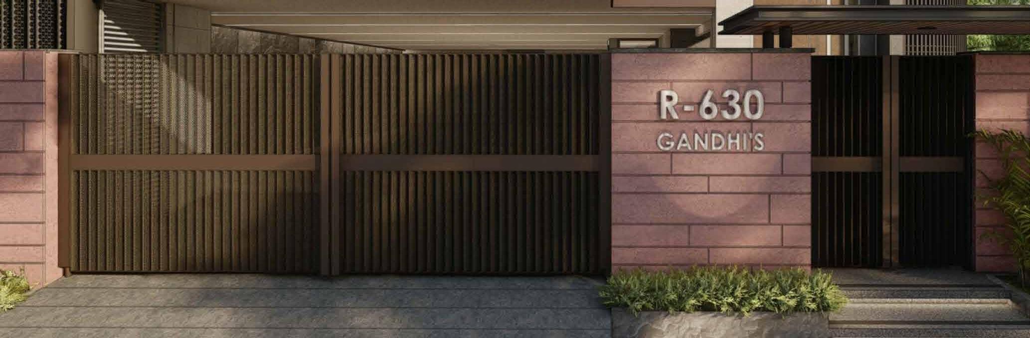
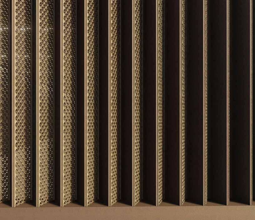
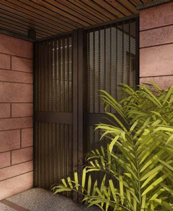
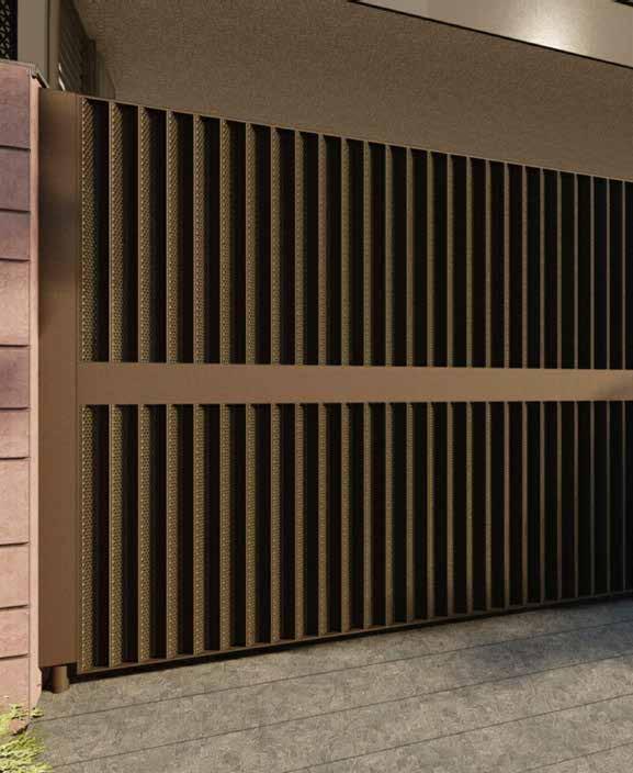
1:50 @A2 SCALE: DRAWING NO DRAWING TITLE: DRAWN BY CHECKED BY REV NO PRINCIPAL DESIGN CONSULTANT MEP CONSULTANT STRUCTURAL CONSULTANT STAGE NAME STAMP NOTE: 1. All dimensions are in millimeters. 2. All levels are in millimeters. 3. This drawing is a copyright and property of the architect, is not to be produced, copied, handed over to third party or used for any other purpose other than for which it is intended. 4. This drawing is to be read and not to be scaled. 5. All dimensions shall be verified on site prior to start of work any discrepancy shall be brought to the notice of the Architect. 6. The Contractor / Project Manager must check all dimensions and details and be responsible for the same. Any discrepancy shall be notice of the Architect. 7. This drawing shall be read in conjunction with all relevant architectural, structural and services drawings. Any discrepancy noticed shall be brought to the attention of the consultants and resolved as soon as possible, but always prior to procurement / execution of works. 8. All the services ducts / cut-outs are to be covered after services provisions. 9. Drawing approval is for the conformity with outline design intent and does not relieve the contractor/ subcontractor from full responsibility for the accuracy, integration and fitness for purpose of design. 10. Construction Manager/Project Manager to revert back within working days of receiving the drawings on coordination and buildability issues. If otherwise it would be deemed that they have understood and accepted the drawing/design and own full responsibility for the works carried out accordingly. PROJECT: SITE: CLIENT: JAPAN SHAH CONSULTING ENGINEER 601, Sixth Floor, Silver Oaks Building, Near Mahalaxmi Cross Road, Paldi, Ahmedabad 380007 Mobile (direct): +91-94264 01793 Gandhi Town House New Delhi UnBox Design Mr. Kovid Gandhi B-119, Ground Floor, East of Kailash, New Delhi - 110065 FOR REVIEW Main Gate Views A-306.3 R2 Issued to PMC 07-12-2022 R0 Purpose Rev. Date Revised Brickwork R1 28-06-2023 Revised gate detail R2 30-03-2024 Revised gate detail R3 22-04-2024 1 View - 01 2 View - 02 3 View - 03 4 View - 04


1:50 @A2 SCALE: DRAWING NO DRAWING TITLE: DRAWN BY CHECKED BY REV NO PRINCIPAL DESIGN CONSULTANT MEP CONSULTANT STRUCTURAL CONSULTANT STAGE NAME STAMP NOTE: 1. All dimensions are in millimeters. 2. All levels are in millimeters. 3. This drawing is a copyright and property of the architect, is not to be produced, copied, handed over to third party or used for any other purpose other than for which it is intended. 4. This drawing is to be read and not to be scaled. 5. All dimensions shall be verified on site prior to start of work any discrepancy shall be brought to the notice of the Architect. 6. The Contractor / Project Manager must check all dimensions and details and be responsible for the same. Any discrepancy shall be notice of the Architect. 7. This drawing shall be read in conjunction with all relevant architectural, structural and services drawings. Any discrepancy noticed shall be brought to the attention of the consultants and resolved as soon as possible, but always prior to procurement / execution of works. 8. All the services ducts / cut-outs are to be covered after services provisions. 9. Drawing approval is for the conformity with outline design intent and does not relieve the contractor/ subcontractor from full responsibility for the accuracy, integration and fitness for purpose of design. 10. Construction Manager/Project Manager to revert back within working days of receiving the drawings on coordination and buildability issues. If otherwise it would be deemed that they have understood and accepted the drawing/design and own full responsibility for the works carried out accordingly. PROJECT: SITE: CLIENT: JAPAN SHAH CONSULTING ENGINEER 601, Sixth Floor, Silver Oaks Building, Near Mahalaxmi Cross Road, Paldi, Ahmedabad 380007 Mobile (direct): +91-94264 01793 Gandhi Town House New Delhi UnBox Design Mr. Kovid Gandhi B-119, Ground Floor, East of Kailash, New Delhi - 110065 FOR REVIEW Boundary Wall Details A-306.3 R2 Issued to PMC 07-12-2022 R0 Purpose Rev. Date Revised Brickwork R1 28-06-2023 R2 30-03-2024 R3 22-04-2024 1205 1 Landscape Plan 1:75 4 refer Sheet A-602 for Ramp detail 202 +150 mm +210 mm 202 TOS FFL Space for Electric LT panel & Electricity meter Double height entrance Space for Water Meter 201 +150 mm +225 mm TOS FFL UP 01 02 03 04 05 06 -320 mm FFL -190 mm FFL -90 mm FFL +10 mm FFL +110 mm FFL +210 mm FFL -600 mm -450 mm Main Road LVL Pedestrian Walkway Ramp(Slope 1:5) DN DN Y04 X01 X02 X03 X05 X07 X04 X06 Y03 Y02 Y01 14311 12005 3450 830 2 Fountain Plan 1:25 5 Fountain Section 2 1:25 +150 mm TOS - STILT - 600 mm FRONT ROAD LVL. +2050 mm BOUNDARY WALL LVL. SER. ROAD ± 00 230mm thk Brick Wall 115mm thk Brick Wall 50mm thk Dark Grey Stone as/selection Sculpture as/architect's Selection Shaft for fountain mechanism 15 mm Water Spouts Balancing Tank Fountain Mechanism Tank 115mm thk RCC wall Space for Fountain Water Motor Water Outlet 50mm thk Stone cut into Grooves of 30mm width 3 Fountain Elevation 1:20 25mm thk Dark Grey Stone as/selection +225mm lvl high Dark Grey Stone 2071 500 1273 709 770 115 115 115 230 50mm thk Dark Grey Stone as/selection +200mm lvl high Dark Grey Stone 25mm thk Stone coping laid to slope 25mm thk Dark Grey Stone as/selection 25mm thk Dark Grey Stone as/selection Curve Edge Detail For less Water Splash 25mm thk Dark Grey Stone as/selection 25mm thk Stone coping laid to slope 25mm thk Stone coping laid to slope 25mm thk Dark Grey Stone as/selection 25mm thk Dark Grey Stone as/selection 50mm thk Stone cut into Grooves of 30mm width +200mm lvl high Dark Grey Stone +225mm lvl high Dark Grey Stone +75mm lvl high Dark Grey Stone 25mm thk Dark Grey Stone as/selection 25mm thk Stone coping laid to slope 4 Fountain Section 1 1:25 1 2 Fountain plan Detail - 01 Detail - 01 Detail - 06 Detail - 09 Detail 08 Detail - 07 1 2 1 2 Detail - 01 Detail 02 1906 2071 1155 938 1906 75 150 400 1155 75 1290 2736 2100 475 679 446 286 335 446 679 311 325 325 475 2049 75 500 500 Detail 11 Detail - 10 R4 26-04-2024 For review For review For review NVR IC GT


1:50 @A2 SCALE: DRAWING NO DRAWING TITLE: DRAWN BY CHECKED BY REV NO PRINCIPAL DESIGN CONSULTANT MEP CONSULTANT STRUCTURAL CONSULTANT STAGE NAME STAMP NOTE: 1. All dimensions are in millimeters. 2. All levels are in millimeters. 3. This drawing is a copyright and property of the architect, is not to be produced, copied, handed over to third party or used for any other purpose other than for which it is intended. 4. This drawing is to be read and not to be scaled. 5. All dimensions shall be verified on site prior to start of work any discrepancy shall be brought to the notice of the Architect. 6. The Contractor / Project Manager must check all dimensions and details and be responsible for the same. Any discrepancy shall be notice of the Architect. 7. This drawing shall be read in conjunction with all relevant architectural, structural and services drawings. Any discrepancy noticed shall be brought to the attention of the consultants and resolved as soon as possible, but always prior to procurement / execution of works. 8. All the services ducts / cut-outs are to be covered after services provisions. 9. Drawing approval is for the conformity with outline design intent and does not relieve the contractor/ subcontractor from full responsibility for the accuracy, integration and fitness for purpose of design. 10. Construction Manager/Project Manager to revert back within working days of receiving the drawings on coordination and buildability issues. If otherwise it would be deemed that they have understood and accepted the drawing/design and own full responsibility for the works carried out accordingly. PROJECT: SITE: CLIENT: JAPAN SHAH CONSULTING ENGINEER 601, Sixth Floor, Silver Oaks Building, Near Mahalaxmi Cross Road, Paldi, Ahmedabad 380007 Mobile (direct): +91-94264 01793 Gandhi Town House New Delhi UnBox Design Mr. Kovid Gandhi B-119, Ground Floor, East of Kailash, New Delhi - 110065 FOR REVIEW Boundary Wall Details A-306.3 R2 Issued to PMC 07-12-2022 R0 Purpose Rev. Date Revised Brickwork R1 28-06-2023 R2 30-03-2024 R3 22-04-2024 1205 1 Detail 1 Plan 1:8 2 Detail 2 1:8 3 Landscape Plan 1:8 4 Landscape Plan 1:8 7 Detail 4 1:8 8 Detail 5 1:8 30 25 30 25 30 25 30 25 30 25 30 25 30 25 30 25 30 25 30 30 25 30 25 30 25 30 25 30 25 25 5 Detail 3 1:8 10 Detail 7 1:8 11 Detail 8 1:8 12 Detail 9 1:8 30mm wide, 20mm deep grooves with 25mm distance in between 890 50 75 75 30 25 30 25 30 25 30 25 30 25 30 25 30 25 30 25 30 25 30 Stone Cladding Clamps Pipe for Water Fountain Mechanism Balancing Tank Fountain tank 15mm wide small drips Balance Tank 30 mm wide inner grooves 25 mm wide groove outer face 25mm thk Stone coping laid to slope Fountain Mechanism Tank 25mm thk Dark Grey Base Stone as/selection 115mm thk RCC wall 25mm thk Dark Grey Groove Stone as/selection 25mm thk Dark Grey Stone as/selection 6 Detial 3.1 1:4 50 25 90 115mm thk RCC wall 50mm thk Grey Stone as/selection +200mm lvl high Dark Grey Stone 300 575 50 115 50 16600 25 75 75 25 25 2075 150 75 50 115 575 50 25 115 400 50 9 Detail 6 1:4 Fountain water outlet face 50 25 25mm thk Stone coping laid to slope 25mm thk Dark Grey Base Stone as/selection 115mm thk RCC wall 150mm thk RCC slab 25mm thk Stone coping laid to slope 115mm thk RCC wall Balancing Tank 150mm thk RCC slab 25mm thk Stone coping laid to slope 255 25 50 300 150 300 25 50 215 400 50 400 50 75 75 150 255 25 50 115mm thk RCC wall 50mm thk Grey Stone as/selection 25mm thk Stone coping laid to slope +200mm lvl high Dark Grey Stone +200mm lvl high Dark Grey Stone +200mm lvl high Dark Grey Stone Small grooved stone forming small drips 115 25mm thk Dark Grey Stone as/selection 25mm thk Dark Grey Stone as/selection Small grooved stone forming small drips 25mm thk Dark Grey Stone as/selection 25mm thk Dark Grey Stone as/selection 30 mm wide inner grooves 25 mm wide groove outer face 25mm thk Stone coping laid to slope Fountain water outlet face 30 mm wide inner grooves 25 mm wide groove outer face 25mm thk Dark Grey Stone as/selection Small grooved stone forming small drips 25mm thk Dark Grey Stone as/selection 115mm thk RCC wall 50mm thk Grey Stone as/selection 25mm thk Stone coping laid to slope Detail - 3.1 R4 26-04-2024 For review For review For review


1:50 @A2 SCALE: DRAWING NO DRAWING TITLE: DRAWN BY CHECKED BY REV NO PRINCIPAL DESIGN CONSULTANT MEP CONSULTANT STRUCTURAL CONSULTANT STAGE NAME STAMP NOTE: 1. All dimensions are in millimeters. 2. All levels are in millimeters. 3. This drawing is a copyright and property of the architect, is not to be produced, copied, handed over to third party or used for any other purpose other than for which it is intended. 4. This drawing is to be read and not to be scaled. 5. All dimensions shall be verified on site prior to start of work any discrepancy shall be brought to the notice of the Architect. 6. The Contractor / Project Manager must check all dimensions and details and be responsible for the same. Any discrepancy shall be notice of the Architect. 7. This drawing shall be read in conjunction with all relevant architectural, structural and services drawings. Any discrepancy noticed shall be brought to the attention of the consultants and resolved as soon as possible, but always prior to procurement / execution of works. 8. All the services ducts / cut-outs are to be covered after services provisions. 9. Drawing approval is for the conformity with outline design intent and does not relieve the contractor/ subcontractor from full responsibility for the accuracy, integration and fitness for purpose of design. 10. Construction Manager/Project Manager to revert back within working days of receiving the drawings on coordination and buildability issues. If otherwise it would be deemed that they have understood and accepted the drawing/design and own full responsibility for the works carried out accordingly. PROJECT: SITE: CLIENT: JAPAN SHAH CONSULTING ENGINEER 601, Sixth Floor, Silver Oaks Building, Near Mahalaxmi Cross Road, Paldi, Ahmedabad 380007 Mobile (direct): +91-94264 01793 Gandhi Town House New Delhi UnBox Design Mr. Kovid Gandhi B-119, Ground Floor, East of Kailash, New Delhi - 110065 FOR REVIEW Boundary Wall Details A-306.3 R2 Issued to PMC 07-12-2022 R0 Purpose Rev. Date Revised Brickwork R1 28-06-2023 R2 30-03-2024 R3 22-04-2024 1205 25mm thk Dark Grey Stone as/selection 25mm thk Dark Grey Stone as/selection 25mm thk Dark Grey Stone as/selection 25mm thk Dark Grey Stone as/selection 25mm thk Dark Grey Stone as/selection 25mm thk Dark Grey Stone as/selection 25mm thk Dark Grey Stone as/selection 25mm thk Dark Grey Stone as/selection 25mm thk Dark Grey Stone as/selection 25mm thk Dark Grey Stone as/selection 25mm thk Dark Grey Stone as/selection 25mm thk Dark Grey Stone as/selection 3 Reference for groove fountain 8 Reference for Drip Slits 2 5 Reference for Drip Slits 1 6 Champa Tree 9 Sculpture 7 Dark Grey Stone Texure 1 Detail 10 1:4 2 Detail 11 1:4 4 Reference for water outlet 1:75 R4 26-04-2024 For review For review For review
1:50 @A2 SCALE: DRAWING NO DRAWING TITLE: DRAWN BY CHECKED BY REV NO PRINCIPAL DESIGN CONSULTANT MEP CONSULTANT STRUCTURAL CONSULTANT STAGE NAME STAMP NOTE: 1. All dimensions are in millimeters. 2. All levels are in millimeters. 3. This drawing is a copyright and property of the architect, is not to be produced, copied, handed over to third party or used for any other purpose other than for which it is intended. 4. This drawing is to be read and not to be scaled. 5. All dimensions shall be verified on site prior to start of work any discrepancy shall be brought to the notice of the Architect. 6. The Contractor / Project Manager must check all dimensions and details and be responsible for the same. Any discrepancy shall be notice of the Architect. 7. This drawing shall be read in conjunction with all relevant architectural, structural and services drawings. Any discrepancy noticed shall be brought to the attention of the consultants and resolved as soon as possible, but always prior to procurement / execution of works. 8. All the services ducts / cut-outs are to be covered after services provisions. 9. Drawing approval is for the conformity with outline design intent and does not relieve the contractor/ subcontractor from full responsibility for the accuracy, integration and fitness for purpose of design. 10. Construction Manager/Project Manager to revert back within working days of receiving the drawings on coordination and buildability issues. If otherwise it would be deemed that they have understood and accepted the drawing/design and own full responsibility for the works carried out accordingly. PROJECT: SITE: CLIENT: JAPAN SHAH CONSULTING ENGINEER 601, Sixth Floor, Silver Oaks Building, Near Mahalaxmi Cross Road, Paldi, Ahmedabad 380007 Mobile (direct): +91-94264 01793 Gandhi Town House New Delhi UnBox Design Mr. Kovid Gandhi B-119, Ground Floor, East of Kailash, New Delhi - 110065 FOR REVIEW Boundary Wall Details A-306.3 R2 Issued to PMC 07-12-2022 R0 Purpose Rev. Date Revised Brickwork R1 28-06-2023 R2 30-03-2024 R3 22-04-2024 1205 1 Fountain Rendered View for Reference 1:75 2 Front View Fountain Mechanism Tank 115mm thk RCC wall Space for Fountain Water Motor 25mm thk Stone coping laid to slope 25mm thk Dark Grey Stone as/selection Curve Edge Detail For less Water Splash Pipe for Water Fountain Mechanism Sculpture as/selection 30 mm wide inner grooves 25 mm wide groove outer face 4 Side View 3 Detailed Reference View R4 26-04-2024 For review For review For review First Fountain pond Balancing Tank


Issued to Contractor 00-00-2022 R0 1:50 @A2 Purpose Rev. Date SCALE: DRAWING NO DRAWING TITLE: DRAWN BY CHECKED BY REV NO PRINCIPAL DESIGN CONSULTANT MEP CONSULTANT STRUCTURAL CONSULTANT STAGE NAME STAMP NOTE: 1. All dimensions are in millimeters. 2. All levels are in millimeters. 3. This drawing copyright and property of the architect, is not to be produced, copied, handed over to third party or used for any other purpose other than for which intended. 4. This drawing to be read and not to be scaled. 5. All dimensions shall be verified on site prior to start of work any discrepancy shall be brought to the notice of the Architect. 6. The Contractor Project Manager must check all dimensions and details and be responsible for the same. Any discrepancy shall be notice of the Architect. 7. This drawing shall be read in conjunction with all relevant architectural, structural and services drawings. Any discrepancy noticed shall be brought to the attention of the consultants and resolved as soon as possible, but always prior to procurement execution of works. 8. All the services ducts cut-outs are to be covered after services provisions. 9. Drawing approval is for the conformity with outline design intent and does not relieve the contractor/ subcontractor from full responsibility for the accuracy, integration and fitness for purpose of design. 10. Construction Manager/Project Manager to revert back within 7 working days of receiving the drawings on coordination and buildability issues. If otherwise would be deemed that they have understood and accepted the drawing/design and own full responsibility for the works carried out accordingly. PROJECT: SITE: CLIENT: JAPAN SHAH CONSULTING ENGINEER 601, Sixth Floor, Silver Oaks Building, Near Mahalaxmi Cross Road, Paldi, Ahmedabad 380007 Mobile (direct): +91-94264 01793 Brick wall R.C.C. Dry wall Partiton Stone LEGEND Grass Blockwork Wardrobe Level Drop Gandhi Town House New Delhi UnBox Design Mr. Kovid Gandhi B-119, Ground Floor, East of Kailash, New Delhi 110065 N Landscape Details A-601.1 For Review 1 Landscape Plan 1:75 1 1 2 2 3 3 4 5 refer Sheet A-602 for Ramp detail 202 +150 mm +210 mm 202 TOS FFL Space for Electric LT panel Electricity meter Double height entrance Space for Water Meter 201 +150 mm +225 mm TOS FFL UP 01 02 03 04 05 06 -320 mm FFL -190 mm FFL -90 mm FFL +10 mm FFL +110 mm FFL +210 mm FFL -600 mm -450 mm Main Road LVL Pedestrian Walkway Ramp(Slope 1:5) DN DN Y04 X01 X02 X03 X05 X07 X04 X06 Y03 Y02 Y01 4 Section - 1 1:50 Stone Cladding as/detail 230mm thk Boundary wall 85mm thk coping beam detail as/structure Plinth Steps Brick work P.C.C bed as/detail 25mm thk Stone coping laid to slop 25mm thk Stone coping laid to slope 85mm thk coping beam detail as/structure 230 350 RCC beam detal as/structure 115mm thk brick planter Stone as/selection Sitting Ledge as/detail PCC bed as/detail Metal work as/Elevation details Double height entrance foyer Cove Light 25mm thk stone laid over 150mm screeding 14311 12005 3450 830 2 Detail 1 1:25 115 3 Detail 2 1:25 Detail1 For Review 26-02-2024 R1 2000 2667 1095 3135(tocheck) 50 R660 1330 (to check) 115 NVR IC GT 5 Section - 2 1:50 8 Section - 3 1:75 Issued to Contractor 00-00-2022 R0 1:50 @A2 Purpose Rev. Date SCALE: DRAWING NO DRAWING TITLE: DRAWN BY CHECKED BY REV NO PRINCIPAL DESIGN CONSULTANT MEP CONSULTANT STRUCTURAL CONSULTANT STAGE NAME STAMP NOTE: 1. All dimensions are in millimeters. 2. All levels are in millimeters. 3. This drawing copyright and property of the architect, is not to be produced, copied, handed over to third party or used for any other purpose other than for which is intended. 4. This drawing to be read and not to be scaled. 5. All dimensions shall be verified on site prior to start of work any discrepancy shall be brought to the notice of the Architect. 6. The Contractor Project Manager must check all dimensions and details and be responsible for the same. Any discrepancy shall be notice of the Architect. 7. This drawing shall be read in conjunction with all relevant architectural, structural and services drawings. Any discrepancy noticed shall be brought to the attention of the consultants and resolved as soon as possible, but always prior to procurement execution of works. 8. All the services ducts cut-outs are to be covered after services provisions. 9. Drawing approval is for the conformity with outline design intent and does not relieve the contractor/ subcontractor from full responsibility for the accuracy, integration and fitness for purpose of design. 10. Construction Manager/Project Manager to revert back within 7 working days of receiving the drawings on coordination and buildability issues. If otherwise would be deemed that they have understood and accepted the drawing/design and own full responsibility for the works carried out accordingly. PROJECT: SITE: CLIENT: JAPAN SHAH CONSULTING ENGINEER 601, Sixth Floor, Silver Oaks Building, Near Mahalaxmi Cross Road, Paldi, Ahmedabad 380007 Mobile (direct): +91-94264 01793 Brick wall R.C.C. Dry wall Partiton Stone LEGEND Grass Blockwork Wardrobe Level Drop Gandhi Town House New Delhi UnBox Design Mr. Kovid Gandhi B-119, Ground Floor, East of Kailash, New Delhi 110065 N Landscape Details A-601.2 For Review 9 Section - 4 1:75 10 Section - 5 1:75 11 Detail - 5 1:5 230mm thk wall Metal cladding clamps RCC Beam 230x300mm - 600 mm FRONT ROAD LVL. SER. ROAD 00 +150 mm TOS STILT UG Tank detail as/structure - 600 mm FRONT ROAD LVL. SER. ROAD 00 +150 mm TOS STILT 230mm thk wall RCC Beam 230x300mm Planter box 150mm thk Pedestrian walkway Siting Stone Bench Planter box 187 100 RCC Slab as/structure Cove light Double height entrance foyer Stilt parking 1943 450 450 450 600 15 18 3 4 6 Detail - 3 1:10 7 Detail - 4 1:10 Plaster 115mm thk Brick wall P.C.C Bed Boundary wall Gravel bed detail as/vendor Bed Rock detail as/vendor Stepping stones Cove light Parking metal gate as/Elevation 230mm RCC wall UGT wall as/structure Filling as/contractor Floor Finish as/architect Sitting Ledge as/detail Planter box Lawn Area RCC Beam 230x300mm 230mm thk wall Stone as/selection Coping stone RCC Slab as/structure Louvers as/elevation details Steps Ramp 150mm thk Pedestrian walkway 5 - 600 mm FRONT ROAD LVL. SER. ROAD 00 +150 mm TOS STILT 115 390 25 25 50 50 718 1353 25mm thk Stone coping laid to slope 25mm thk Stone coping laid to slop 18mm thk Stone coping laid to slope Stone Cladding as/detail Cove Light Stone Cladding as/detail 25mm thk Stone coping laid to slope 85mm thk coping beam detail as/structure 85mm thk coping beam detail as/structure 25mm thk Stone coping laid to slope 35 450 380 838 Water Body as/architect 205 25 10 100 150 50 150 125 50 180 115 265 115 450 2475 2450 Water Outlet 25 mm thk Dark Grey Stone as/selection 50 mm thk stone cut into grooves of 30 mm 625 550 For Review 26-02-2024 R1
