19 minute read
Lightning protection for radiocommunication sites
Phillip R. Tompson
A total system approach can protect radiocommunication sites from even direct lightning strikes to towers, antennas and powerlines.
It is not difficult to understand why radiocommunication stations are so prone to lightning strikes. Sites are generally located on elevated ground and mountain tops and have an antenna tower or mast prominently located to optimise radio coverage for the surrounding areas. The tower and its antennas are therefore highly susceptible to receiving direct lightning strikes.
In addition to direct strikes to transmitting structures, direct and induced lightning strikes to powerlines feeding equipment buildings must also be considered.
Strike incidence There are two common statistics used to measure the incidence of lightning strikes. The first is the term ‘thunderday’. This term is defined as a calendar day during which thunder is heard at a given location. The international definition of lightning activity is given as the number of thunderdays per year. This is also called the ‘isokeraunic level’.
Thunderday maps are published by meteorological organisations worldwide. As may be expected the number of thunderdays is generally greatest in tropical regions around
©stock.adobe.com/au/dima266f
the equator and falls off as one progresses north and south towards the poles.
Another commonly used statistic to record lightning activity is the ‘lightning flash density’. This is defined as the number of lightning flashes to ground occurring on or over unit area in unit time. This is commonly expressed as per square kilometre per year (km-2 year-1).
As may be expected there is a relationship between thunderdays and ground flash density.
To assess the susceptibility of the antenna structure to lightning, the number of likely strikes per annum can be readily calculated. The attractive radius of tall, slender structures typical of antenna towers can be found by use of an equation for Ra:
Ra = I0.64 x h(0.66 + 2 x I x 0.0001) where
Ra = the attractive radius for the structure, in metres
I = the prospective lightning stroke current amplitude, in kiloamperes h = the structure height, in metres
Using the above equation, a structure with a height of 30 m and a prospective lightning stroke current of 130 kA, which accounts for 99% of all lightning strikes has an attractive radius of 309 m.
The collection area is then given by:
Ac = π x R a 2 x 10⁻⁶ where
Ac = the collection area for the structure, in square kilometres.
A 30 m-high transmitting mast will have a collection area of 0.300 km2 .
Finally, the prospective number of strikes per annum can be calculated from:
P = A c x N g where
P = the prospective number of strikes per annum
Ng = the ground flash density km-2 year-1
In an area with 150 thunderdays, which is typical of Malaysia, the mean ground flash density is 15. So a 30 m-high antenna tower will receive on average 4.5 direct strikes every year.
This is a statistical calculation but provides ample evidence of the need for effective lightning protection at these sites.
The lightning strike The transient discharge of electric current that occurs between a negative charge centre and a positively charged region is a lightning flash. A typical flash is made up of one or more discharge components or pulses, with each pulse consisting of a negative leader stroke and a positive return stroke.
On a normal fine, sunny day the earth has a slight negative polarity, and the electric field so created is about 300 V per metre. As a thunder cloud forms, separation of electric charge in the cloud creates a surplus of negative charge in the base of the cloud and over a period of many minutes this will build up to create an electric field
rain
Figure 1. Charge build-up.
Up draughts of warm air Down draughts of cold air Negative charge cloud base Positive charge on top

Charge build up in clouds Electric eld intensi cation
Positive charge on ground Air breakdown leads to stepped leader
Figure 2. Development of the downward leader.
in the order of 10 kV per metre. Imagine the electric field as essentially horizontal lines, as per Figure 1.
Charge build-up continues until the electric field is so great that ionisation of the air occurs. As ionisation occurs, the stepped leader extends from the cloud towards ground bringing electric charge with it.
Figure 2 shows a building or other structure. The effect of this structure is to distort the electric field as its top is at earth potential. The field lines now must curl around the building, creating field intensification at the top and corners.
As the leader approaches ground, the electric field builds up further and field intensification occurs around those objects above ground level. The degree of field intensification depends upon the height of the structure or object.
At some point the breakdown electric strength of air will be reached and ionisation will occur. This gives rise to an ‘upward streamer’ which heads up to meet the downward leader.
For tall structures streamer creation is most likely around points of high field intensification, ie, at the tops of antenna towers and masts and the corners and other extremities of buildings.
One of the upward streamers will meet the downward leader and complete the ionisation path. The electric charge is then discharged via this path and the so called ‘return stroke’ current flows. The return stroke current flow collapses the electric field and it is this collapse in electric field that is responsible for induced voltages in power conductors and other metallic conductors.
Thus, the structure must be protected against direct strikes plus the indirect effects of a nearby strike creating induction due to the collapsing electric field after the lightning flash.
Protection principles When lightning strikes a tower that is grounded the current pulse, which typically may have a rise time of 1 microsecond and a decay to half amplitude of 50 microseconds, will flow down the tower to ground.
It is important to be aware that no matter what form the lightning protection takes there will be a potential gradient developed up the tower. This potential is essentially caused by the self-inductance of the tower. The self-inductance of a 30 m-high tower is 25 microhenries.
The potential at the top of the tower may be calculated from the following formula:
V = L x dI/dt where
L = Self-inductance in microhenries dI/dt = Rate of rise of current in amps per microsecond
For a 50 kA current rising in 1 microsecond, the potential at the top of the tower will be approximately 1.25 MV.
It is not possible to reduce this voltage build-up. Any protection system must take this into account.
As the current pulse flows to ground a rise in ground potential will also occur. By ignoring the effects of inductance and considering resistance of the earthing system alone, this earth potential rise can be easily calculated.
For example, a 50 kA impulse flowing to ground with a 10-ohm earth resistance will raise the earth potential by 500 kV.
Continuation of downward leader
Further electric eld intensi cation
Upward positive streamer generation Streamer meets downward leader

Figure 3. Development of the upward streamer.
● Positive upward streamer meets the downward leader
Conducting path forms ● Potential is equalised by Figure 4. The return stroke.
the "return stroke"
Visible lightning ash
Since the local ground potential rises, any cables leaving the vicinity of the tower will carry this potential to the transmitter building. Current will flow along coaxial cable sheaths and create a potential between the inner and outer conductors of these cables.
At many stations, the tower can often be located some distance from the equipment building so it cannot even be assumed that both the tower and building earth will rise to the same potential.
Whether the tower is struck by lightning or lightning strikes the incoming powerline, surge protection on all incoming services is essential. The aim is to reference all incoming services to the local ground either directly or via surge diverting components such as surge diverters, power surge filters, coaxial cable protectors etc.
Direct strike protection A direct strike to an antenna tower is unlikely to damage antennas unless the antenna itself is struck or correct earthing and bonding principles have not been adhered to.
Antennas which form the highest point of the structure and are not at tower potential are particularly vulnerable and it is difficult to protect these effectively. High-gain whip antennas mounted at tower top are typical examples. The best form of protection is to carry some spares.
Where antennas are mounted on the lower faces of the tower, it is usual to erect a vertical spike, or Franklin rod, at the top of the tower to act as the air terminal. To be effective, the top of the rod needs to be at least 3 metres above the highest point of the antenna.
No special precautions with regard to down conductors on all-steel towers are necessary. The four legs of a self-supporting tower provide an excellent path for the lightning impulse current.
Special air terminals and proprietary down conductors consisting of custom-made coaxial cables etc are totally unnecessary. They do nothing to reduce the potential rise at the top of the tower and cannot possibly be insulated to the level required to prevent flashover to the tower itself.
Concrete towers and masts can utilise the concrete reinforcing, ladder and any other steel work for the down conductor path. Earthing and bonding Since a direct strike to the tower will raise earth potentials and cause current to flow in feeders and coaxial cable sheaths, it is essential to pay attention to correct earthing and bonding practices. • Ensure that the antenna system is securely bonded to the tower structure. • Bond the sheath of the feeder cable to the tower structure at the antenna. • Bond the sheath of the coaxial feeder to the tower structure at the point where it leaves the tower. Do this just prior to the bend in the feeder. This will divert current on the feeders to ground. • Ensure that the tower is securely earthed.
For a 50 kA lightning impulse every oneohm reduction in earth resistance will reduce the earth potential rise by 50 kV. • Bond the sheath of the cable to the station ground at the point of entry to the equipment building.
Figures 5 shows the principle of earthing and bonding to create a common earth with single point earthing in the building and bonding of tower and building earths.
● = Bonding points
Figure 5. Earthing and bonding points.
Building layout The geometry of the interconnections in and around the building are of vital significance to the effectiveness of the lightning protection system. The objective is to provide a path for the potentially destructive lightning current flowing from the antenna to the AC supply line via a path that does not include the interior of the building.
The ideal building layout would be one where the coaxial feeders, AC supply and other services enter the building at one point. At this point all services are connected to the building ground either directly in the case of coaxial cable sheaths, water pipes etc, or via surge protection devices in the case of AC power, telephone, coaxial feeders etc.
It is impossible to reduce earth resistance to zero so there will always be earth potential rises developed when lightning strikes. By carrying out the above procedures a single earth will be produced such that an equipotential earth rise will occur and current flow in the building through vital equipment will be eliminated.
AC power surge protection The AC supply line to the building usually represents the lowest impedance to remote grounds and will therefore carry much of the lightning current flowing away from the site. The surge protection installed must thus have sufficient capacity to carry these currents.
This situation is altogether different from the case of induced voltages in powerlines, for which many surge protection devices are designed.
It is usual to choose mains power filters in preference to shunt connected surge diverters. The filters provide multistage protection and redundancy in the event of a component failure. In addition, their letthrough voltage is low enough to protect the most sensitive electronic equipment. Shunt connected surge diverters are not.
Generally, three-phase versions with surge ratings no less than 120 kA would be employed. Current ratings depend on the station requirement. For typical cellular GSM sites this would be in the order of 40-plus amps per phase. These filters are installed at the building point of entry of the AC power supply.
Coaxial cable protection At high frequencies, the components used in power filters are unusable. Metal oxide varistors have a high self-capacitance which shunts RF energy. The only useable device is the gas-filled arrester, which may be connected between the inner and outer sheaths of coaxial cables to clamp differential voltages.
Such devices are readily available for low-power transmitting and receiving equipment up to a few hundred watts.
When lightning strikes a communication tower, the potential at the top of the tower rises. This has already been established. Antennas located at the top of these towers must also be subjected to these potential rises. Antennas that are fed with coaxial cables must have their inner and outer conductors both subjected to these potential rises.
At the building entry the lightning energy can be diverted to earth by the action of bonding the coaxial feeds to earth. The inner conductor of these cables must also be protected. This is done by coaxial surge protectors which divert energy from the inner conductor to earth. A recommended procedure is to establish a station earth bar, then use bulkhead mount coaxial protectors mounted on this earth bar to provide the termination point for incoming coaxial feeders.
For cellular telephone sites there are two specific cases to be considered. 1. The protection of cellular antennas requires special attention. Gas arrestertype surge protectors, as described above, are not recommended. Instead, quarter-wave, stub-type surge barriers are to be preferred. They offer superior performance in terms of let-through voltage and minimal intermodulation.
Quarter-wave stub-surge barriers are particularly useful on transmitter cables and offer superior performance on receive antennas. Active receive antennas with power feed up the feeder require gas-filled arrester types both at the equipment and head ends. 2. Link equipment that uses microwave bearers with active head units requires special attention. Protection is required at both the head and equipment ends.
Attention must be paid to the signals, baseband, IF and power on the interconnecting cables.
In conclusion, the protection from lightning of radiocommunication sites can be achieved and protection from even direct lightning strikes is possible. There are no short cuts, and systems which purport to enhance the attraction of lightning, divert lightning, dissipate lightning or prevent lightning should be rejected.
Phillip R Tompson is Technical Director at Novaris. He is a chartered member of IE(Aust), IEE, and IEEE as well as a member of the Australian Standards Committee on lightning protection.
Handheld radio The Sepura SC21 is a TETRA hand-portable radio that has a wide range of functionality inherited from the SC20 handportable, in a unit that is 25% smaller. Class 3 high-power RF transmission, coupled with its receive sensitivity, gives the SC21 extended operational range. The SC21’s audio capability enables clear voice communication in noisy environments. A directional speaker projects audio to the user’s ear, providing extra clarity, and Water Porting technology ensures that clarity is maintained even in continuous, heavy rain.
The SC21’s worker safety features include automated man-down and lone worker protection, biometric user health monitoring and location tracking. Its 2.4″, high-resolution QVGA screen enables viewing in all light conditions, including direct sunlight.
Sepura PLC
www.sepura.com
Cable and spectrum analysers The three pocket-sized SiteHawk cable antenna analyser models cover 300 kHz to 200 MHz, 1 MHz to 4500 MHz and 20 MHz to 6 GHz. Fully selfcontained, the units feature an intuitive interface that is readily accessible to the first-time user and minimises clicks for the expert. There is the ability to download results to USB, and each unit includes the Bird RF Meter App to perform power measurement using external sensors.
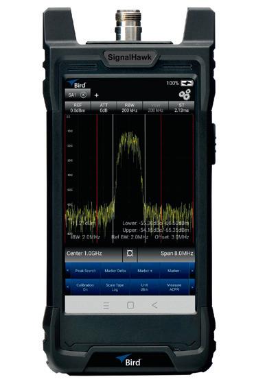
The SignalHawk family of handheld spectrum analysers provides functionality in a compact, affordable package. Highly portable, the analysers easily fit in one hand and have an intuitive touchscreen user interface. The SH-60S-TC RF analyser enables user to view RF signals between 9 kHz and 6 GHz, while the SH-60S-AOA RF analyser extends the capability of the SH-60S-TC by adding the ability to triangulate the location of an interferer on a map.
Radio Matters
Some members of RFUANZ have mentioned that the Department of Conservation (DOC) concession process and interpretation by DOC seems to differ from region to region, which can greatly affect concession charges for the applicant. We are interested to hear if members would like RFUANZ to work with DOC to clarify and tidy up the concessions?
Please let us know any issues that you have had with DOC concessions, and any areas that you would like to be addressed.
The rural broadband industry is able to have their first three years of concessions waived under the Rural Broadband Initiative (RBI). RFUANZ would like to see what DOC would be willing to do for our members with new concession applications.
I look forward to hearing from you with any feedback you can provide on these matters.
At our meeting in September, the RFUANZ committee decided to move to bimonthly newsletters. As there will not be a newsletter in November, I urge you to attend the annual meeting of RFUANZ via Zoom if possible. Alternatively, please complete the proxy form, available on request from our administrator.
We have had one vacancy on the RFUANZ committee for several months, with a further two members standing down at the upcoming meeting. Therefore again, I urge you to please complete a nomination form if you know of someone within your company who would be interested in joining the committee.
Any costs incurred by the member in order to belong to the committee will be covered by RFUANZ, including a per-meeting attendance rate, paid at the end of the 12-month term. The committee meets once per month, via Zoom, for approximately 1 to 2 hours.
The RFUANZ AGM will be held via Zoom at 4:00 pm on 11 November 2020. You are invited to attend. We require a minimum representation of at least 30 as we have a change to our Rules that needs to be adopted at the AGM.
To register for the meeting, please contact admin@rfuanz.org.nz.
As per Clause 15.5 – Alteration of Rules: These Rules may be changed by a special resolution of a meeting of Members at which at least 30% of the members are present.
This means we need to ensure at least 30 members are present, or have submitted a proxy voting form, in order to adopt the change to our Rules. The remit to be tabled is that the current Rule 19.1: Definitions and Interpretations, be amended as follows to include postal voting: “Post” or “Postal” can include “Electronically” in all instances where written notice either of an annual general meeting, ballot vote or termination of membership appears in these Rules.
The reason for this is that this year during the COVID-19 pandemic, we have been unable to hold our annual general meeting, nor gather in numbers for any occasion. In today’s technological world we have been able to continue with work as usual, using Zoom and webinar meetings. A move to adopt posted items electronically will enhance this further, with a much better, faster and more economical form of communication.
Included with the AGM papers, to be mailed out early next month, will be a proxy form that we request you complete and return your vote regarding this Rule change.
Also with the AGM papers will be a nomination form that needs to be completed and returned to our administrator, should you or someone you know of, who is a current financial member of RFUANZ, wish to be a representative on the RFUANZ committee. For more information, please contact either myself or Candice, admin@rfuanz.org.nz, or post to PO Box 40-525, Upper Hutt, 5140.
Corey Weir Chairman, Radio Frequency Users Association of New Zealand

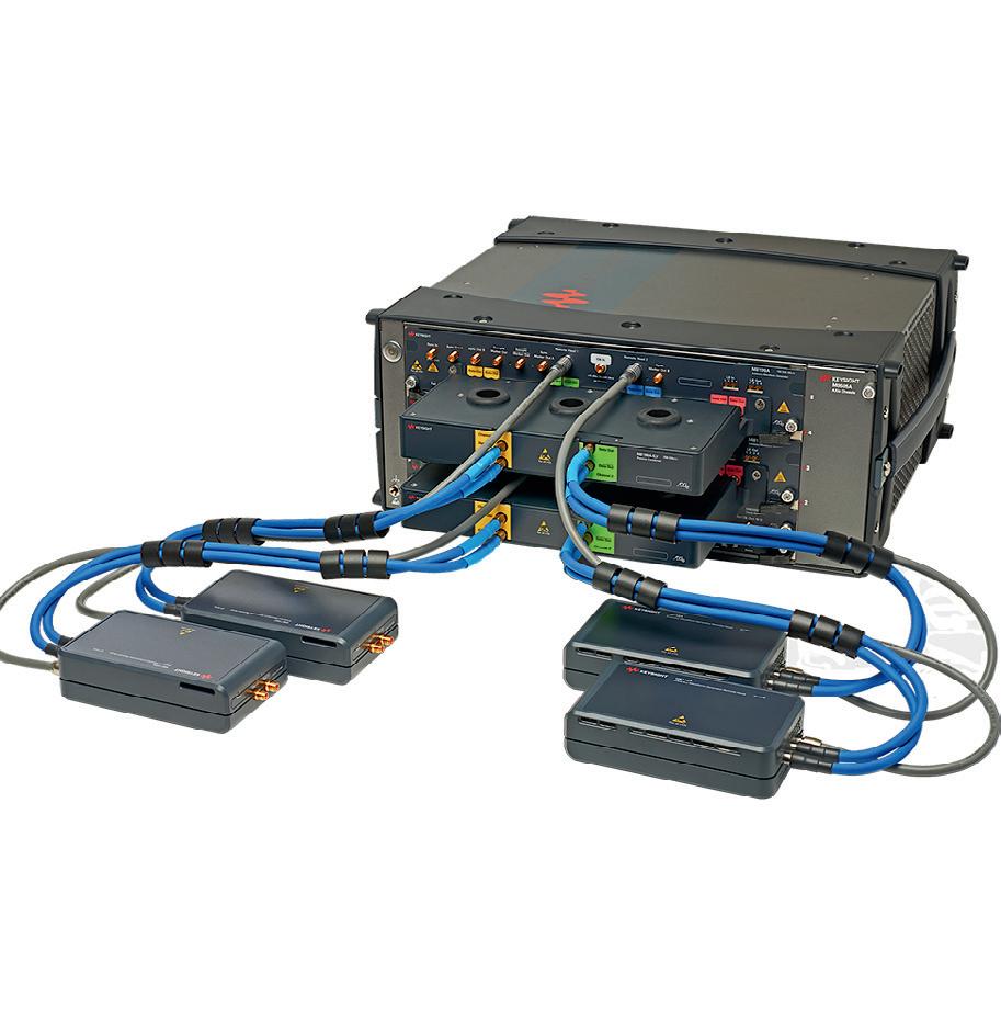
Waveform generator The M8199A is Keysight Technologies’ first 256 GSa/s arbitrary waveform generator (AWG), featuring 65 GHz analog bandwidth in a compact 2-slot AXIe module.
A new DAC-ASIC that translates memory data into an analog signal, an RF connector placed at the DAC-ASIC and amplifier technology with a smooth frequency roll-off have resulted in a useable signal bandwidth beyond the nominal 65 GHz even up to 80 GHz.
The M8199A provides research engineers with a source for arbitrary signals, enabling development of designs that push beyond current limitations. Applications include testing the discrete components of an optical coherent transmission system or experimenting with terabit transmission for data centres.
Keysight Technologies Australia Pty Ltd
www.keysight.com
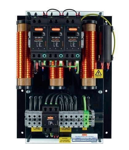
Surge filters Novaris Surge filters are made in a wide range of sizes for all conditions to provide a high level of protection to critical equipment, from 6 to 2000 A. They feature handmade inductor coils together with high-quality capacitors to form a high-end LC circuit. Coupled with primary and secondary surge protection, they provide optimum power filtering and surge protection in one unit, for protecting everything from the smallest radio to the largest transmitter site.
Novaris Pty Ltd
www.novaris.com.au
Accredited testing and global product approvals since 1992
Bayswater
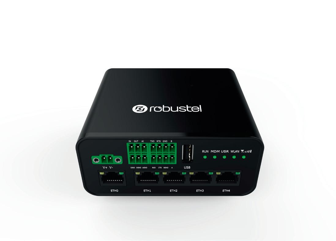
Router The Robustel R1520 industrial IoT router/gateway from Glyn offers 5x Ethernet ports for access and control of a wide variety of remote industrial applications, as well in-vehicle usage thanks to its in-built GPS chipset. The unit offers a 2-wire RS485 interface for connecting legacy instruments with full Modbus support, as well as an RS232 port featuring RTS/CTS lines to accommodate applications that require hardware handshaking. For industrial users, it includes optically isolated digital inputs and outputs as well as a 10-bit analog input capable of interfacing directly with sensors in the range of 0 to 24 VDC or 0 to 20 mA.
The R1520 offers WAN failover and dual-SIM connectivity to 4G/LTE Cat-4 networks with coverage for the majority of frequency bands used worldwide. The unit is powered by Robustel’s proprietary Linux-based operating system, RobustOS, enabling users to install a variety of applications to enhance the router’s interoperability with various systems including industrial protocol convertors, VPNs and interfaces into common IoT cloud platforms.
Glyn Ltd
www.glyn.com.au

