23 minute read
Sanitary temperature sensor calibration
Sanitary temperature sensors are commonly used in many industries, but their calibration is different and more difficult than for normal temperature sensors. T emperature is one of the critical process parameters in many industries and the accuracy of the temperature measurement in processes is a crucial consideration. The food and beverage, dairy, pharmaceuticals and life science industries have additional requirements for temperature measurement sensors because of their processes. They require temperature sensors that are sanitary, meaning that these sensors need to be suitable to be installed in hygienic and aseptic process environments. These sensors need to be hygienic and designed to be easy to clean, often supporting clean-in-place (CIP) processes. The mechanical design needs to be free from any cavities, dead pockets, gaps or anything that would complicate the hygienic cleaning. Surface finishes of these sensors are hygienically graded and need to meet the strict standards in these industries, such as the 3-AR (https://www.3-a.org/) or EHEDG (European Hygienic Engineering & Design Group) https://www.ehedg.org/. The material of the wetted parts in these sensors is often high-grade stainless steel, suitable for these applications, and for easy installation, the sanitary sensors are often provided with the clamp installation.


The temperature ranges typically go up to around 150°C, or in some cases up to 200°C, which in itself is not very challenging.
The role of calibration
In any industry, it is vital that the process measurements measure correctly and as accurately as designed. This can be achieved with the help of suitable process instruments and with a proper calibration program.
Within the food and beverage, pharmaceutical and life science industries, calibration plays an even more important role than most other industries. In these industries, the consequences of a bad or a failed calibration can have a dramatic effect, as we are talking about consumer and patient health and safety. As failed calibration can be very costly in these industries, it has to be avoided by all means possible.
These industries also have dedicated strict regulations concerning calibration.
Why are sanitary sensors difficult to calibrate?
than 100 mm and typically around 50 mm, but can also be as short as 25 mm. The diameter of the sensor typically is 3 mm or 6 mm.
The commonly used practice in temperature calibration (and a Euramet guideline recommendation) is that a temperature sensor should be immersed deep enough in a temperature bath to achieve sufficient accuracy. The recommendation is to immerse to a depth that is 15 times the sensor diameter (plus the length of the sensor element). But with these short sanitary sensors, it is simply impossible to immerse the sensor to sufficient depth during the calibration. For example, a typical sanitary sensor with a diameter of 6 mm should be immersed to at least 90 mm (15 x 6 mm) depth during the calibration to ensure accurate results. But if that 6 mm sensor has a length of only 50 mm, sufficient immersion is simply not possible.
Some rules of thumb for the immersion depth when calibrating in a liquid bath are: • 1% accuracy: immerse five diameters plus the length of the actual sensing element inside the sensor • 0.01% accuracy: immerse 10 diameters plus the length of the sensing element • 0.0001% accuracy: immerse 15 diameters plus the length of the sensing element

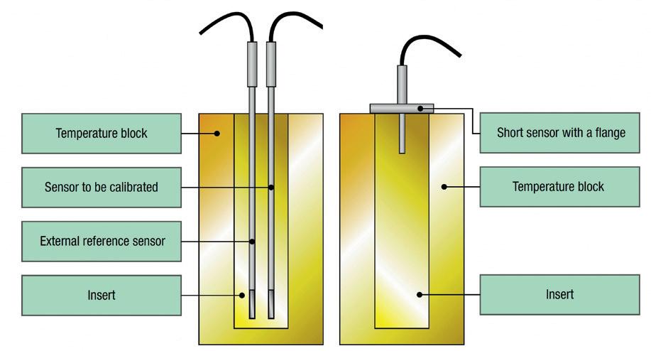
Figure 1: Error versus immersion. Figure 2: Calibrating normal temperature sensors versus a sanitary sensor with a flange.
The accuracy in the above rule is to be calculated from the temperature difference between the block temperature and the ambient temperature.
For example, if the ambient temperature is 20°C and the block temperature is 120°C, there is a 100°C difference. If you then immerse the probe only five times the dimension (plus the sensing element length) — say you have a 6 mm probe with a 10 mm sensing element inside of it and you immerse it 40 mm (5 x diameter + sensing element) — you can expect about 1°C error due to the low immersion (1% of 100°C).
Figure 1 illustrates the relationship between thermometer immersion depth (in diameters) and the relative error of the temperature difference (of the temperature block and ambient temperatures). So if you don’t immerse at all, you naturally get a 100% error, and if you immerse deep enough the error caused by immersion becomes insignificant.
This rule of thumb can become quite significant at higher temperatures or for extremely short sensor lengths, and so this should be kept in mind with sensors less than 40 mm.
It is not always easy to know the length of the actual sensing element inside the probe. If that is not mentioned in the datasheet, you can ask the manufacturer. Sanitary sensors often have a clamp connection with a flange As mentioned previously, sanitary sensors also often have a socalled clamp connection (Tri-clamp, ISO 2852, DIN 11851, DIN 32676, BS 4825, Varivent, etc), so there is a relatively large metallic flange that causes heat to conduct away and leak from the sensor to the flange. In practice this means that the flange causes the sensor to read a slightly lower temperature when calibrating to a temperature higher than ambient temperature. Liquid bath or a dry block?
Generally you can calibrate temperature sensors in a liquid bath or in a dry block. Pros and cons of a liquid bath A liquid bath makes it easier to insert any shape of sensors and you can also use a reference probe inserted at the same time. Depending on the size of the liquid bath, you may be able to insert several sensors to be calibrated at the same time. In case the sensor to be calibrated is an odd shape, a benefit is that it will still fit inside the liquid bath. A liquid bath often enables better uniformity and accuracy than a dry block due to better heat transfer via the liquid.
Even though this sounds like a favourable option, a liquid bath also has several drawbacks: • A liquid bath always includes some sort of liquid, such as silicone oil, and often you don’t want to contaminate the sanitary sensor in such a liquid. Cleaning is necessary after the calibration to ensure that the sensor is clean when installed back into the process. • Handling of hot oil is dangerous and any spills may cause injuries. • Liquid baths are very slow. Even fitting several sensors in at the same time, it is often several times slower than a dry block, so overall effectiveness is not really any better. Sometimes several baths are used, each set to a different temperature, but this is a very expensive way to calibrate. • The sanitary sensor should be placed so that the surface of the liquid touches the bottom of the flange, but in practice this is not always that easy to do. For example, silicone oil has a large thermal expansion, which means that the surface level is changing slightly as the temperature changes. So, you may need to adjust the height of the sanitary sensor during the calibration. • Liquid baths are often large, heavy and expensive pieces of equipment. Pros and cons of a dry block The main pros of calibrating the sanitary sensor in a dry block are: • Because it is a dry, it is also clean and does not contaminate the sanitary sensor to be calibrated. • A dry block is very fast to change temperature. • When using a dedicated insert with proper drillings, it is easy to insert the sanitary sensor the same way each time, and the calibration is repeatable every time and with different users. • A dry block is light and easy to carry compared to a liquid bath. • Typically, a dry block is also cheaper than a liquid bath.
On the downside, a dry block is a less accurate than a liquid bath, which typically only calibrates one sanitary sensor at a time and needs different inserts drilled for different diameter sensors.
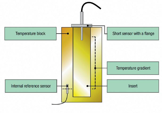
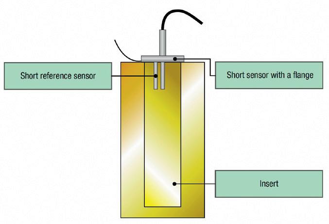
Figure 3: The internal reference sensor is usually too low to be accurate with sanitary sensors. Figure 4: Using a dedicated short reference sensor.
Despite these downsides, customers often prefer to make the calibration of their short sanitary sensors in a dry block.
How to calibrate in a temperature dry block
To calibrate these short sanitary sensors in a temperature dry block, there are a few considerations to take into account. Using a reference sensor Firstly, when you do the calibration in a dry block, the flange of the sanitary sensor makes it impossible to use a normal external reference sensor in the same insert.
Comparing the calibration of a normal (long, no flange) temperature sensor using a reference probe with a short sanitary sensor with a flange (Figure 2), we can see that the short sensor flange covers all the holes in the insert, so it is not possible to insert a normal reference temperature probe. Using an internal reference sensor The dry block always includes an internal reference sensor. Trying to use the internal reference sensor in the dry block does not work with short sensors, because the internal reference sensor is located close to the bottom of the temperature block, and the short sensor to be calibrated is located in the very top part of the insert (Figure 3). Dry blocks typically control the temperature gradient on a limited range in the bottom of the insert. The top part of the insert typically has a larger temperature gradient, so the top of the insert does not have the same temperature as the bottom of the insert. The size of the gradient depends on the temperature difference between the insert and environment, and how deep you insert the sensor. Using a dedicated short reference sensor As the internal reference sensor in the bottom of the dry block is not suitable, we need to use a dedicated external reference temperature sensor. The aim is to use a dedicated reference sensor that is short enough so that it can be immersed to the same depth as the sanitary sensor to be calibrated. Optimally, the middle of the sensor elements should be aligned to the same depth.
Also, the reference sensor needs to have a thin flexible cable so that the cable can fit under the flange of the sanitary sensor. To help that, we can make a groove in the top of the insert where the reference sensor cable fits and the flange of the sanitary sensor still touches the top of the insert.
Naturally the structure of the temperature dry block needs to be such that the sanitary sensor with the flange fits in its place and touches the insert top end. In some dry-blocks the surroundings prevent the flange from going deep enough to touch the top of the insert.
Locating the reference sensor at the same depth as the short sanitary sensor to be calibrated ensures they are measuring the same temperature. Also, the reference sensor cable is in the groove, so it does not prevent the flange of the sanitary sensor from touching the top of the insert (Figure 4). Short sensor without a clamp connection There are also short temperature sensors without the clamp connection and without the flange. With these sensors you should also use an external reference sensor that has been immersed to the same depth as the sensor to be calibrated. The reference sensor should be as similar as possible to the sensor to be calibrated, with a similar diameter, similar response time, etc.
Documentation, metrological traceability and calibration uncertainty
As documentation is included in the formal definition of calibration, it is a vital part of every calibration. This is naturally also valid in sanitary temperature sensor calibration — typically in the form of a calibration certificate.
The calibration equipment used should have a valid metrological traceability to the relevant standards, otherwise the calibration does not ensure traceability in the sensor calibration.
The calibration uncertainty is also a vital part in every calibration. If the calibration equipment (and calibration method and process used) is not accurate enough for the sensor calibration, then the calibration does not make much sense.
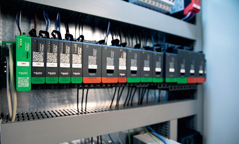

DIGITAL LOAD MANAGEMENT SYSTEM
TeSys island is a smart, digital multifunctional load management system that can switch, protect and manage motors and other electrical loads of up to 80 A. It is designed to help prevent unplanned stoppage and enables the early detection of abnormal load behaviour. By automating routine tasks, leveraging simulation technologies and having a design that reduces wiring and enables faster mounting to DIN rail, TeSys island can reduce time to market by up to 30%.
With this smart load management system, commissioning and operation are also made easier. TeSys island can be used to integrate machines to IT using open standards and allows users to commission remotely. It also reduces machine downtime, enhancing maintenance efficiency with faster information tracking.
By using TeSys island, users can generate up to 50% time saving on corrective actions. Pumping, packaging and conveying are common applications for TeSys island, but it can also be used in other industrial and commercial applications. It is compatible with third-party PLCs and all industrial fieldbuses.
Schneider Electric
www.se.com/au
RFID SECURITY READERS
IDEC Corporation has announced the KW2D series of smart radio-frequency identification (RFID) readers, which are designed for easy installation into the typical 22 mm panel-mount holes used with machinery and are readily integrated with automation systems.
The RFID readers are compact, UL-listed, all-in-one devices installed into typical 22 mm panel-mount holes right along with other switches, buttons and lights. They maintain IP65/67 water-, dust-, and oil-proof ratings, and feature push-in power supply terminals. A built-in Ethernet port facilitates easy connectivity to host devices like PLCs and HMIs using Modbus TCP. Three-colour white/green/red LED lighting is clearly visible from the front and sides to indicate standby, successful verification or error respectively, while a built-in auxiliary buzzer provides audible feedback of successful and error conditions.
Users can mix and match various RFID tag formats: commercial-style cards, wristbands, stickers, and IDEC-supplied colour-coded key fob or card-style tags. The key fob tags are available in five colours, durable for field conditions, and include enhanced encryption compared with other tag types.
RFID tags are passive devices that respond to a short-range radio signal generated by the RFID reader when the two are in close proximity. The KW2D operates at standard 13.56 MHz high-frequency (HF), providing a reading distance of up to 15 mm depending on the tag style. Several ISO/IEC communication speeds (type V, A or F) are supported.
IDEC Australia Pty Ltd
www.idec.com/australia
SAFETY I/O MODULES
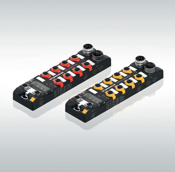
Turck has expanded its range of safety I/O components with the TBPN and TBIP block I/O modules for Profisafe and CIP Safety respectively. The IP67/IP69K modules provide safety input and output signals directly from the field to the safety controller, or they can alternatively be used as decentralised safety controllers in the field. This function optimises modular machinery and also applications in which long bus cycle times to the central controller would require greater safety distances. Safety functions can also be tested offline with the local safety controller function before the machine or the machine module communicates with a central controller. Commissioning work is considerably faster when the devices are used in combination with a custom web server. The block I/O devices provide four safety inputs and four universal inputs or outputs (FDX) in the field. The flexibility of the FDX ports in particular enables optimum coverage of the individual safety signal requirements of any application. The modules can be used for applications up to PL e, category 4, in safety circuits up to SIL CL 3. Actuators are provided with 2 A per output, with up to 9 A in total. With protection to IP65/IP67/IP69K and an extended operating temperature range from -40 to +70°C, the fully potted block modules can withstand harsh environments.
PILZ INTRODUCES THE FIRST BATCH SIZE 1 SAFETY RELAY

The myPNOZ safety relay from Pilz monitors safety functions such as E-Stop, safety gates, light curtains, two-hand controls IIIA/C and enabling switches. It consists of a head module with up to a maximum of eight expansion modules that can be freely combined.
In the corresponding online tool myPNOZ Creator, users can assemble a needs-based safety solution from a wide range of options. Users can switch between a logic view and a hardware view. The option for visualisation and extensive documentation is also available via simulation.
Logical, safe engineering
Depending on the safety requirement, users interconnect safety functions such as E-Stop or safety gate using logic AND/OR connections. The myPNOZ Creator online tool uses a symbol to indicate any logic errors in the safety function sequence. Users can add any further safety functions at will and also defi ne details — such as delay-on energisation and delay-on de-energisation for example. Users can check immediately whether a circuit or safety design meets their own requirements in the myPNOZ Creator, using the simulation in the online tool. As a result, errors can be reduced and commissioning accelerated.
Safety: simply create, simulate safely and order with time to spare
In the myPNOZ Creator it is possible to defi ne the number, type and logic connections between the safety functions, based on what the user needs for their plant. The Creator uses these details to automatically calculate which modules are needed and the sequence in which they must be inserted. The plug-in sequence results from the connection logic for the safety functions. Due to this internal combination logic, the process requires no programming knowledge. The product that is generated can be ordered directly via the online tool, and users can order a previously defi ned confi guration of myPNOZ with just a click of the mouse. The safety relay is delivered pre-assembled and ready to install. Each myPNOZ is given a unique type code, so that if necessary the same system confi guration can be reordered at any time.
Comprehensive modularity for greater fl exibility
The myPNOZ safety relay monitors consists of a head module with up to a maximum of eight expansion modules, which can be freely combined. The modular myPNOZ offers up to 12 different expansion modules in total: four output modules, four input modules and four input/output modules. Each input module can monitor two safety functions, which not only minimises hardware costs but also reduces the wiring. Multiple safety sensors can be monitored without the need to wire multiple relays — as was the case previously. With myPNOZ it is also possible to form multiple safety zones, which independently monitor plant sections that operate separately. This helps to increase the availability of the plant because machine parts can be shut down independently from each other.
The slimline 17.5 mm head module already has a higher-level safety function. This works on all outputs, regardless of any other potential safety zones. The output modules either switch immediately or with a time delay and are available with relay or semiconductor outputs. myPNOZ enables safety functions to be AND/OR linked, enabling customised applications.
Fast, simple assembly
The modules on myPNOZ are easily connected using bus connectors, and the whole system is supplied with power via the head module. As a result, only the head module needs to be connected to the power supply, which reduces wiring. The plant can be commissioned quicker and can also be optimised with a view to maintenance costs: if just one module needs to be swapped, individual modules can be exchanged immediately without dismantling the whole system. myPNOZ also has expanded diagnostics via LED for each module and each safety input. This accelerates troubleshooting and reduces downtimes.
The range of modules and the fact that they are easy to handle mean that users can always assemble the solution that’s right for them. That guarantees users maximum fl exibility over the whole lifecycle, even when subsequent changes are needed.
Wide-ranging applications
myPNOZ represents an efficient, safe solution for mechanical engineering. What’s more the safety relay can be used in various industries. Users benefi t with safety applications of simple to average complexity, when two to a maximum of 16 safe input functions are to be monitored, without using engineering software. For more information, go to www.mypnoz.com.
INDUSTRIAL DATA ACQUISITION SYSTEM
The Dewesoft IOLITEd is an industrial data acquisition system designed for easy-to-use industrial data acquisition and monitoring applications. All signal amplifiers are designed to offer high-end signal conditioning with 24-bit resolution and a high sampling rate of up to 50 kHz/channel.
With its range of input and output slots, the product allows the measurement of a wide range of parameters including voltage, current, strain, stress, vibration, sound, temperature, digital and counters.
High-quality data acquisition hardware combined with Dewesoft X data acquisition software performs data collection without losing a single sample, according to the company. It also provides data visualisation and processing capabilities.
Data can be stored in a time-series database and served to SCADA systems using standard interfaces such as OPC UA or XCP to support Industry 4.0 applications.
A wide variety of amplifiers with different channel counts per module allow suitable channel distribution for monitoring. Systems can be distributed with 100 m distance between the modules and good signal quality due to short sensor cable length.
Units are synchronised with each other and can use external timing sources like GPS for precise synchronisation of dislocated units.
IOLITEd devices are standard EtherCAT slave devices that are compatible with any EtherCAT master controller. When connected to Dewesoft X software, retransmit functionality ensures no samples are lost during measurement.
Metromatics Pty Ltd
www.metromatics.com.au


HEAVY-DUTY SWITCHGEAR

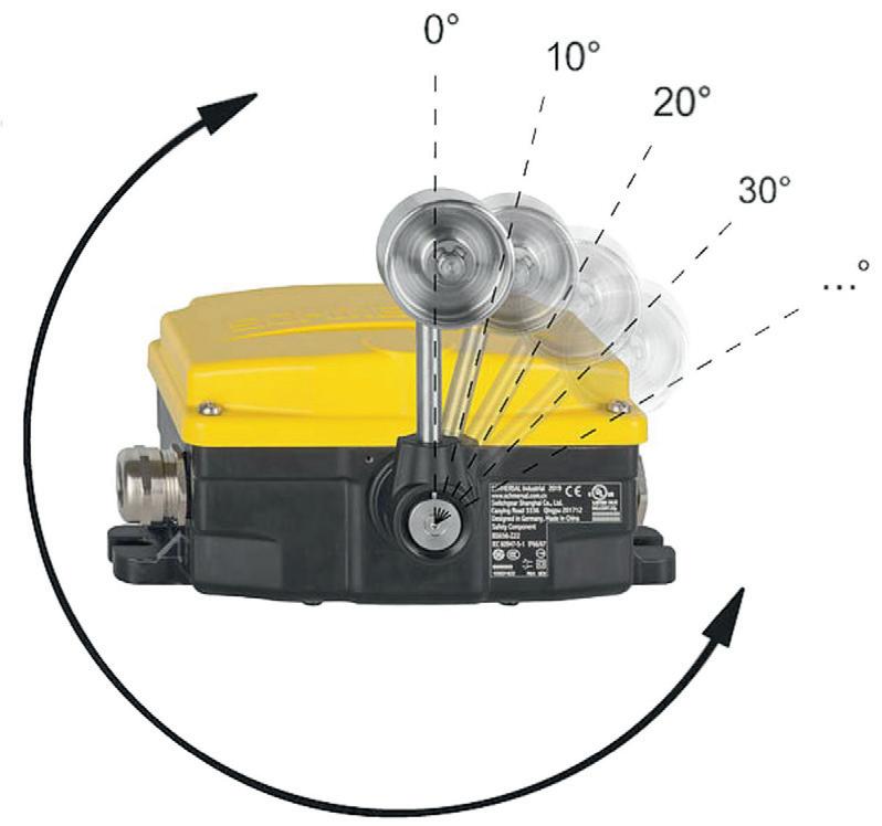
The Schmersal HDS switchgear series is designed for use in heavy industry. The modular series unites a range of functions into a single platform, making it suitable for a wide range of applications.
The basis of the platform is the standardised enclosure concept, which is available in two versions: plastic (Duroplast) and grey cast iron. The plastic version is resistant to aggressive media and especially suitable in port logistics applications and loading and unloading operations, as well as in the agricultural industry in the processing of fertilisers, minerals and phosphates. The robust grey cast iron version is suitable for industries such as mining or bulk materials and extraction.
The function range is also divided into two basic versions: the emergency-stop, designed as a pull-wire switch (RS655/RS656), and the position monitoring (BS655/BS656). The basic switch on the position monitoring version can be flexibly combined with a range of actuation elements. Typical application areas include emergency-stop deactivation, belt misalignment monitoring in the transport of bulk materials, end position monitoring in steel-making and level monitoring in material silos. IP66 and IP67 protection make them suitable for use in extreme environmental conditions.
All basic versions can be optionally connected to the Dupline installation bus or AS-I-Safety-at-Work for quick and easy networking, series switching and improved transfer of diagnostics data. Central connecting terminals with CAGE and CLAMP technology also help to reduce installation times.
Control Logic Pty Ltd
www.controllogic.com.au
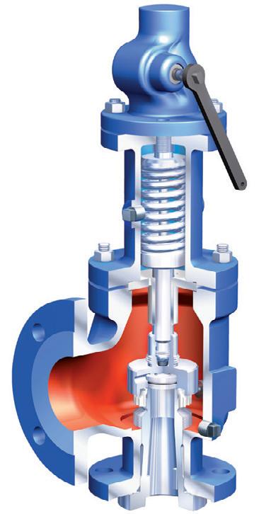
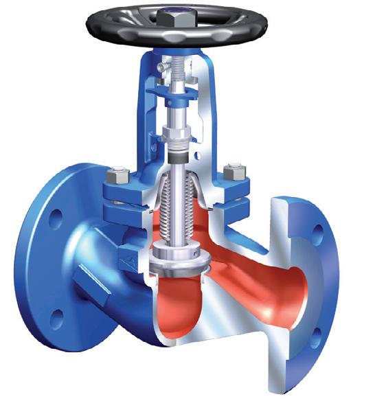
Ari vAlves solutions for pipelines.

• Steam • Oil & Gas • Chemicals • Process & Control • Mining • Water • Shipping
Globe valve with bellow Seal
FABA®
Full Nozzle SaFety valve
(API 526) ARI-REYCO™
triple oFFSet proceSS valve
ZETRIX®
Large raNge of SafeTy aNd ProceSS vaLveS IN STock for ImmedIaTe deLIvery.
auSTraLIaN ageNT & STockIST
Tel: (03) 9699 7355
9303P&SS-WNIPT6
VALVE ACTUATORS WITH AC POWER
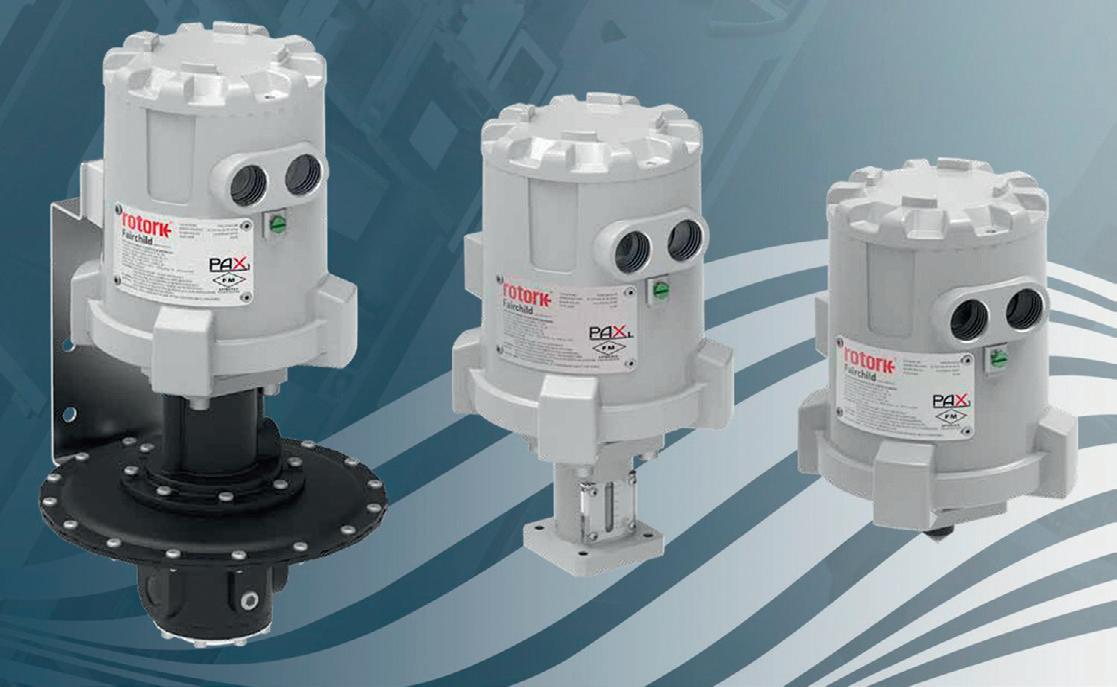
The wider Rotork PAX range of linear valve actuators is made up of a variety of linear actuators and motorised regulators. PAX1 units are flexible, low-voltage actuators that are suitable for use in remote explosion-hazard locations. They offer a thrust output of up to 2890 N (650 lbf), enabling control of most regulators, small valves and pumps. They are capable of controlling pressure ranges of 0–0.5 psig to 0–3000 psig.
Common applications include pump stroke control, valve control, test equipment and the automation of mechanical spring-loaded pressure regulators. Hazardous area rated to FM, CSA and ATEX, they also have high levels of ingress protection; NEMA 4X, Type 6P, IP66 and IP68 (7 m for 72 hours), increasing the areas in which they can be used. They have a wide ambient temperature range of -40 to +80°C.
The addition of an AC power variant allows for longer cable runs without degradation of the power supply. This allows PAX series units to be installed within existing installations where DC power does not exist or is too expensive or difficult to run.
The PAX1 is suitable for midstream and downstream natural gas systems demanding precision and reliability, such as natural gas distribution automation. The AC PAX1 is especially well suited for water and power industrial applications. In the water industry, the integration of an AC PAX1 unit allows for optimisation and control.
Rotork Australia
www.rotork.com
HMI/PLC DEVICES
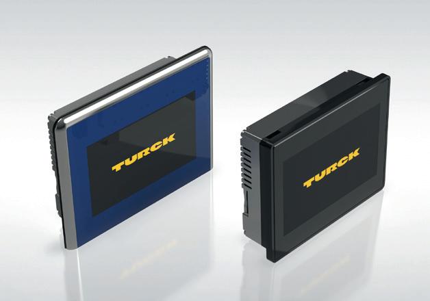
Turck has expanded its TX700 HMI/PLC device series with two variants for food and beverage applications (TX700FB) and two variants with high brightness displays for sunlight readability (TX700HB). The FB devices are available in 7″ and 15″ screen diagonals and the HB variants in 7″ and 10″ screen diagonals.
The FB devices were developed to comply with hygienic design requirements (DIN EN1672-2, EHEDG/FDA 21 CFR 177.2006) and come with a stainless steel front with a polyester coating. The device front has been designed with protection to IP69K so that the devices are waterproof at high pressure up to 80°C. The FB products are also resistant to acids and chemicals. The HB devices with their extra bright display up to 800 cd/m2 are particularly suitable for outdoor applications. The displays are manufactured with liquid bonding (LOCA) — a screen bonding process that improves screen contrast and increases brightness through reduced reflection and refraction. The HB devices with the full metal housing are resistant to mechanical influences.
The TX100, TX200, TX500 and TX700 device series enables Turck to offer a flexible range of HMI devices for visualisation, as well as HMIs with Codesys PLCs and a cloud connection.
Turck Australia Pty Ltd
www.turck.com.au
SERIAL-TOETHERNET DEVICE SERVER
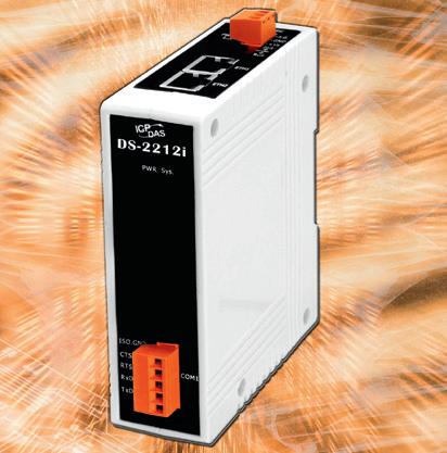
The ICP DAS DS-2200i is a serial-to-ethernet device server that is designed to add Ethernet and internet connectivity to any RS-232/422/485 device and to eliminate the cable length limitation of legacy serial communication.
By using the VxComm Driver/Utility, the built-in COM port of the DS-2200i can be virtualised to a standard PC COM port in Windows. Serial devices can be accessed or monitored transparently over an Ethernet network without software modification. With two ethernet ports, the DS-2200i allows daisy chain connection, which enables flexibility in locating devices for easy installation and lower infrastructure costs.
The DS-2200i also adds 3000 VDC isolation and ±4 kV ESD protection that diverts the potentially damaging charge away from a sensitive circuit.
The VxComm Driver/Utility supports both 32- and 64-bit Windows 10/8/7/2008/2003/XP. The virtual COM works transparently and is protocol independent.
ICP Electronics Australia Pty Ltd
www.icp-australia.com.au
