12 minute read
Twelve common Industrial Ethernet mistakes
Whether you’re a process or plant engineer, a technician, or an electrician, you’ve got to be an expert in a wide array of areas today — including Industrial Ethernet. Sooner or later, you’re going to run into a problem caused by others who aren’t as well-versed in the vagaries of this networking technology. Here are the worst problems that you may face when dealing with Industrial Ethernet. Hopefully, you can find and correct them (or, better yet, avoid them) before they lead to plant downtime.
1. Using office-grade connectors, cables, and network gear
for how long? Non-industrial gear isn’t ready for the vibration, moisture, electrical interference (EMI), chemicals, and more that you’ll find in a plant. Smart people realise this, but sometimes they use suboptimal gear for a quick fix to get operations back up and running. Since quick fixes are often forgotten, it’s best to avoid using non-industrial gear for your Industrial Ethernet.
2. Careless cable routing
Some cabling is designed to handle the worst of all the MICE (mechanical, ingress, climatic, and electromagnetic) environments, so you can be a little looser in how you route that cable. In most instances, however, cabling has some limitations and you need to be aware of those limitations when routing it. Is it too close to electromagnetic interference sources like variable frequency
drives? Are there areas where it will get too hot or exposed to harsh chemicals or just plain water? The worst part about making this mistake is that the cable will usually function properly — until things change just enough to cause a failure.
3. Not labelling your cabling installations
Just as plants have requirements and standards for the labelling of piping and conduit, so does cabling (see TIA 606-B). The issue here isn’t safety, but time and frustration. Knowing which cable goes where can save vast amounts of time when troubleshooting or upgrading.
4. Not testing cabling before installing a new line
Verifying your cabling can save hours of time when you’re installing and starting a new system. While a quick check of the cable takes only seconds, problems like an improperly terminated connector, or a cable that’s too long or susceptible to EMI, can take hours to troubleshoot and lead to finger-pointing and project delays.
5. Not testing extended cabling parameters
Basic cable testing as described above can help ensure that the cabling is installed properly, but it can’t tell you how it will perform. Advanced testers measure many more parameters, such as crosstalk (which affects the throughput of the cable), resistance and return loss (which can indicate connectors that are susceptible to vibration or moisture), as well as transverse conversion loss (which indicates susceptibility to electromagnetic interference). Ensuring that cabling meets performance standards for these parameters provides assurance that the cabling will work not only at startup but well into the future.
6. Using ‘digital extension cords’
One quick fix that’s often attempted for a cable that isn’t performing properly is to connect it to an unmanaged switch somewhere in the middle of the link and run a cable from there to the end device. While this sometimes works it adds a point of failure, which is especially problematic if the device is an office- or consumergrade product. Worse, when connected like this, the device can’t be controlled and is in fact ‘invisible’ to network management or any tech trying to troubleshoot a problem.
7. Trusting the link LED
Connecting a cable to a device and seeing the Link LED illuminate is satisfying, but it’s not a guarantee that the communications link is working properly, or even at all. The link light will typically come on whether the communications are solid or barely working — which means very little margin for error. Most experienced networking techs can tell you stories of the time the light came on when the link didn’t work at all or wasn’t even connected. That’s why they don’t trust those lights, and neither should you.
When your Industrial Ethernet network stops working, it looks good and feels good to start fixing things. Unplug and plug things. Try a different switch port. Route a new cable. Replace a controller. Unfortunately, this scattershot approach has multiple problems. First, you could waste a lot of time fixing things that aren’t broken. Second, it can be costly to replace things that aren’t broken. Third, and worst of all, since you don’t know what the problem was when your communications start working again, you can’t be sure you’ve really solved the issue or if it will be back again to ruin your day tomorrow.
9. Being unprepared for the leading cause of Industrial Ethernet failures
Research shows that the most common cause of Industrial Ethernet failures is cabling and connectors. The good news is that with a small investment you can be ready to quickly pinpoint and repair them. Having a cable tester on-site — even a basic one — not only enables you to determine if the cabling is at fault (if not, you can focus on the real problem) but also tells you where the problem is: most commonly a connector. Having termination tools and replacement connectors (maybe even spare cabling) onsite will save hours or days compared to purchasing them or hiring an expert.
10. Neglecting fibre inspection and cleaning
If your Industrial Ethernet installation includes fibre, you know that the most common cause of fibre failure is contaminated connector end faces — an especially severe problem in dirty or dusty factory environments. Since fibre connections handle more data and are more likely to be critical, failure can be catastrophic. Avoid problems by inspecting and, if necessary, cleaning and reinspecting any fibre connections whenever they are connected or reconnected.
11. Installing fibre-optic cable and not testing it
Fibre-optic cable is often used between the access switches (usually near a machine) and distribution or core switches. They are also used in place of cable runs too long, or inhospitable to copper cable. But like many network components, a marginal fibre link may work well at startup, only to give you trouble down the line. Testing the fibre after it’s installed ensures that it exceeds performance requirements and can even pinpoint potential points of failure.
12. Excessively long cables
No matter how good your copper or fibre cable is, there are limits to how long it can be. The danger of exceeding these limits is not only that it won’t work, but worse, that it will work intermittently — leading to unplanned downtime. Testing your cables before startup or during troubleshooting can tell you if they’re too long. What most people don’t know is that cabling performance degrades as the ambient temperature rises. Cabling standards acknowledge this by applying a derating factor to copper cables in high temperature locations, resulting in a shorter allowable length. You can check for this issue by measuring the insertion loss and return loss of the cable at operating temperature to make sure these critical measurements are within limits. For situations where you need a link that’s too long for standards, talk to your cabling vendor about specialised cabling designed to extend copper operating distance for your MICE environment.
LIGHT CURTAINS
The Allen-Bradley GuardShield light curtains include the CIP Safety over EtherNet/IP module along with integrated laser alignment, muting, blanking and cascading.
Light curtains are an essential safety mechanism in a manufacturing plant, particularly those requiring cutting and chopping before packaging a final product. Staff need access to the product without having to regularly open and close guarding, which is where GuardShield safety light curtains are designed to help with their innovative design to ensure the safety of personnel. The design also helps to reduce maintenance and spare parts. The integrated CIP Safety over EtherNet/IP modules provide detailed diagnostics and status information to Logix DLR networks to cascade to multiple 450L or other EtherNet/IP products together. Most light curtains on the market contain a transmitter and receiver stick, but the GuardShield curtain leverages patented plug-in transceiver technology. Each stick can be used as either a transmitter or receiver via innovative plug-in modules, resulting in fewer parts being required. To significantly reduce engineering effort, the GuardShield range was designed with embedded functions that are configured quickly and easily via DIP switches or software, including muting, blanking, start mode, external device monitoring and scanning ranges.
The range also features an Integrated Laser Alignment System (ILAS), designed for quick installation and reliable operation, which reduces alignment labour time. This can amount to cost savings when installing 450 L units across multiple locations, and improved up-time regarding maintenance and hardware-replacement efforts.
The units come in different lengths ranging from 150 to 1950 mm — in multiples of 150 mm in both 30 mm hand and 14 mm finger resolutions. There are no dead spots (passive zones) at the top or bottom of the stick, which means they can be installed inside a machine frame and do not have to be mounted outside or on the machine like a traditional light curtain system.
NHP Electrical Engineering Products Pty Ltd
www.nhp.com.au

STRAIN WAVE GEARBOX
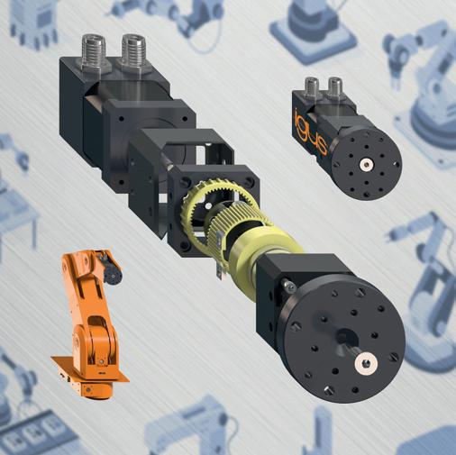
In order to generate accurate movement along the 5th robot axis, igus has developed strain wave gears based on its tribo-polymer technology. Due to the use of lubrication-free polymers, they are compact and light, and also require very little maintenance.
The main components of the gearbox include a wave generator and a flexible ring with outer drive teeth, as well as an outer ring, fixed in place in the housing, and a rotary power take-off element with inner drive teeth. The wave generator has an elliptical shape, therefore the surrounding flexible ring also assumes this shape. The drive teeth of the flexible ring engage at two places in the inner drive teeth of the outer ring and power take-off element. As the outer ring has two teeth more than the other components, the flexible ring is only moved two teeth further per rotation when the wave generator is rotated. Along the last axis of an articulated arm, linear robot or delta robot, the strain wave gear can be used before different gripper systems. Here, it performs the task of gripping objects that are not rotationally symmetrical and positioning them exactly.
The current version is based on a NEMA 17 installation size for direct connection to a stepper motor and can be adapted to other types of motor. With a transmission ratio of 28:1, the gearbox has a service life of 1 million cycles under a load of 1.5 Nm and at a speed of 6 rpm.
Treotham Automation Pty Ltd
www.treotham.com.au

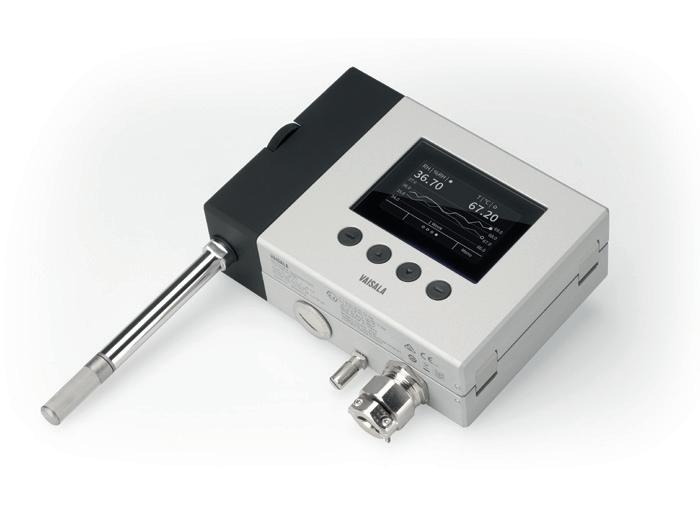
The Vaisala HUMICAP HMT370EX intrinsically safe humidity and temperature transmitter series offers an improvement in robust design over the previous HMT360 series and is said to be more easy to use.
The series is designed specifically for hazardous and explosive environments. The entire transmitter can be installed directly in explosive areas, up to Zone 0 and Zone 20.
Typical applications include paint booths in the automotive industry, hydrogen-cooled generators in electricity generation, chemical plants and processes, the baking industry, pharmaceuticals manufacturing, oil and gas drilling platforms, and fuel tanks and storage.
The series consists of the transmitter and a wide selection of probes. The transmitter is equipped with an intuitive graphical display for ease of use. Hand-detachable measurement probes and easy product configuration and calibration with Vaisala Insight software enable smooth maintenance, minimising any downtime in the measurement. Several probe options are available for different applications. In addition to measuring relative humidity and temperature, the transmitter outputs dew point temperature, wet-bulb temperature, absolute humidity, mixing ratio, water concentration, water mass fraction, water vapour pressure and enthalpy.
Vaisala Oyj
www.vaisala.com/en/
TANK OUTLET VALVE
SPX FLOW has added an additional model of tank outlet valve to its APV D4 series mix-proof valves. The valves enable users to clean the pipeline without having to empty the contents of the tank; this improves efficiency and eliminates changeover costs, saving time and reducing operating costs.
The valves are designed to enable separation between the tank and servicing pipeline in sanitary applications across industries including food and beverage, dairy, pharmaceuticals and cosmetics.
The tank side holding pressure is greater than 5 bar (73 psi) and a long stroke provides for gentle product handling and low flow resistance
Inventory costs are reduced as the same seal kit can be used on multiple size ranges: DN40-DN65 (1.5″–3″) and DN80-DN100 (4″). The valve also has low air consumption and air supply requirements, and a leak drain with clamp connection for CIP fluid collection.
SPX Flow Inc
www.spxflow.com/au


FANLESS EDGE AI COMPUTER
The Neousys SEMIL-1300GC Series is a wide-temperature fanless graphics edge AI computer supporting an NVIDIA Tesla T4 or Quadro P2200 GPU card for demanding environments. Coupled with an Intel Xeon E or 9th/8th-Gen Core CPU, the system is said to deliver high CPU and GPU performance for modern edge AI applications.
Additionally, the wide-temperature GPU computer features Neousys’s thermal system architecture to provide -25 to +70°C fanless operations in a rack-mountable or wall-mountable 2U 19 ″ enclosure.
The series provides M12 connectors for Gigabit PoE+, USB 2.0, VGA and COM ports to offer rugged cable connectivity. Other high-speed computer I/Os include DisplayPort, USB 3.1 Gen1, optional 10Gb Ethernet and storage interfaces, such as M2 for NVMe SSD and SATA ports.
Backplane Systems Technology Pty Ltd
www.backplane.com.au
PORTABLE DRY BLOCK TEMPERATURE CALIBRATOR
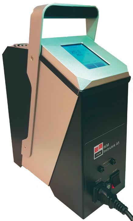
IKM Instrutek has introduced a calibrator with touch display and a calibration interval up to three years. It is designed to meet the market requirements to save cost by extending the calibration interval.
With a contemporary design, the TC65 portable dry block temperature calibrator is developed to meet the toughest demands of environments.
The unit is compact and robust, designed for marine, industrial and laboratory use, approved according to DNVGL-CG-0339:2019(parts of). This is to ensure that users are be able to calibrate a vast range of temperature sensors, thermometers and temperature switches/thermostats.
TC65 specifications include: temperature range from 30 to 650°C; stability ±0.1°C; accuracy 1 year ±1.5°C; and accuracy 3 year ±3.5°C.
The dry block principle excludes the use of oil or other liquids. A dry block insert with various diameters ensures thermal contact to the sensor being tested.
To use, place the sensor to be calibrated in the calibrator. Set the temperature. When stabilisation occurs, read the true temperature from the calibrator and re-calibrate the sensor or system accordingly.
AMS Instrumentation & Calibration Pty Ltd
www.ams-ic.com.au


