
16 minute read
Protecting sensors in weld cells


THE FASTEST WAY TO DRAMATICALLY INCREASE WELD CELL PRODUCTIVITY
Improving sensor survivability in weld cells is one of the easiest and fastest ways to reduce unplanned downtime and lower cost.
When it comes to sensors, cables and connectors in weld cells, weld cell management people are so used to the high cost of constant replacement, downtime and lost productivity that they begin to think it’s natural that weld cells are just that way. Sensors are constantly damaged by loading impact. Slag, weld debris and heat ruin not only the sensors, but their associated connectivity.
It gets to the point that most people involved with weld cells start thinking there’s not much you can do about the wastage but put in a vending machine or some kind of sensor dispensing system close at hand — as if having replacement parts nearby is a viable process improvement.
It’s time to break the high sensor wastage paradigm
It’s time to dispel the myth that maintaining weld cells equals high costs, constant replacement and frequent maintenance episodes. The reason that many weld cells have such high sensor replacement costs is that the sensors used may not match the application, or they are incorrectly placed in the cell, insufficiently protected from heat, slag and impact. And it doesn’t end there. Often connectivity is supplied using the wrong cable jacketing material. Sensor mounts are often of the wrong design for weld cell service or they are manufactured from the wrong materials such as lightweight plastics that are vulnerable to weld hostilities.
© Stock.Adobe.com/au/ taaee
Problem: Heat and slag

High ambient temperatures and weld debris, also known as weld slag or weld berries, attack sensor enclosures, faces, connections and flimsy plastic mounting brackets. Solution 1: Choose the right sensor Choose the right sensor for the right application in every cell location, taking into account the type of welding being accomplished. Sensors are rated devices and are application-specific. MIG, TIG, laser and resistance welding all have their own unique set of characteristics. Not every cell location can accept the same sensor type.
Coated sensors provide a thermal barrier and resist weld debris, slag accumulation and, to a degree, resist impact on the sensor face, while steel-faced sensors tend to be more robust and impact resistant.
Try to use only flush (shielded) sensors in weld cells. They can be surrounded or encapsulated in metal and there’s less potential of shearing off the exposed coil as with tubular non-flush types. Sensors with one-piece gun-drilled stainless steel housings stand up to major incidental impacts, and some have long-range characteristics which, combined with PTFE coatings, give them long-term survivability in tough weld cell applications. Solution 2: Protect your sensors and connectivity Protect your sensors by applying a total heat and slag solution to your sensors, cabling and connectors.
An application-specific coating applied to the face of a proximity sensor repels weld slag accumulation and protects it from damage even in the most severe welding environments. For the connectivity, start with a high durability TPE cable, and then cover the cable, sensor and its protective products with silicone tubing and weld wrap. This system guards the cable and secures the jacket in its proper location while sealing remaining connectivity components against harsh, hot weld spray.
PVC jacket material on connectors should never be used in a weld environment. PVC burns through quickly and can become extremely brittle in a short period of time. PUR styles (polyurethane) offer a better degree of nick resistance, flex characteristics and resistance to welding debris, but TPE (thermoplastic elastomer) takes the positive aspects of PUR to a higher degree of performance.
While TPE cables have outperformed other cable materials such as PVC and PUR, there are additional steps that can be taken to protect connector cables. Tubular silicone jacketing, cut to length and applied to the cables back from the connector will protect the cabling from ambient temperatures of up to 260°C as well as prevent slag build-up on the cabling.
There is also silicone wrap, which is a self-bonding, non-adhesive silicone tape that once applied like tape on a hockey stick, will protect the sensor and connector from slag and heat just as well as silicone jacketing. Once applied, the wrap bonds to itself, becoming a solid barrier to heat and slag, protecting anything it is applied to.
Problem: Parts loading impact
Parts to be joined, or completed components that are loaded and unloaded either manually or by robot, are often dropped on exposed and vulnerable sensors, physically destroying the sensor or the entire sensing system. If an inductive proximity sensor located on a clamp is hit by metal to be joined, usually through loading impact, extensive sensor damage and premature failure may result. Solution: Impact protection Bunker and protect! Mechanical protection is central to the integration of any sensor in hostile manufacturing environments. Mechanical accessories provide a means of rapid change-out and act as a heatsink, while guarding against the heaviest of direct impact and weld debris.

Figure 1: Sensor with weld slag and connector damage.

Figure 2: A sensor damaged by impact.
The greater the protection, the longer the sensor life. Using a bunker block in conjunction with a quick-change prox mount protects the sensor body and face from debilitating physical damage. Prox mounts and bunker blocks are made of machined aluminium or steel and can be PTFE coated. PTFE coating significantly prolongs sensor life by providing a thermal barrier to protect against heat. It also retards the build-up of weld slag spatter and spray, and eases removal of surrounding deposits of weld debris during scheduled maintenance periods.

Problem: Sensor connection failure
Sensor cable connections are a major point of failure. Connectors need to be designed to withstand the hostile weld cell environment. If a sensor cable’s connection has too much stress from slag build-up or if it has the wrong angle, tension and pressure on the connection will cause premature failure. Heat, slag accumulation and flexing of the cable cause connectors to break at the most vulnerable location.
Most sensor types are generally hard-wired to M12 DC Micro or M8 Nano-style connectors. One of the largest problems with sensors in weld cells revolves around the issue of cable and connector burn through. Solution: Connector protection Use only the highest grade of connectors available. TPE exhibits excellent chemical, lubricant, flex, heat, nick, coolant and pinch resistance. There are several models that can function with every sensor found in the typical weld facility, facilitating standardisation and transparency in the organisation. Follow proper cable exit geometry to avoid creating stress on the cable connection, especially in the presence of heat and other weld hostilities.
Once again, seal your entire sensor+connector+mounting system with self-fusing, self-bonding silicone wrap that’s rated to 260°C. It is clear so LEDs can be observed, and it guards connections against fine weld spray, while eliminating the need for hose clamps (which attract weld berries) and vulnerable zip ties for attachment.
Problem: Inadequate mounting brackets
Plastic mounting brackets deteriorate rapidly in welding environments. This contributes to false sensing, no sensing or increased vulnerability of the sensor itself. Moreover, with these brackets, sensor bodies are usually not encapsulated, exposing them to high heat, weld debris spray and impact.
Figure 4: Sensor protection elements.
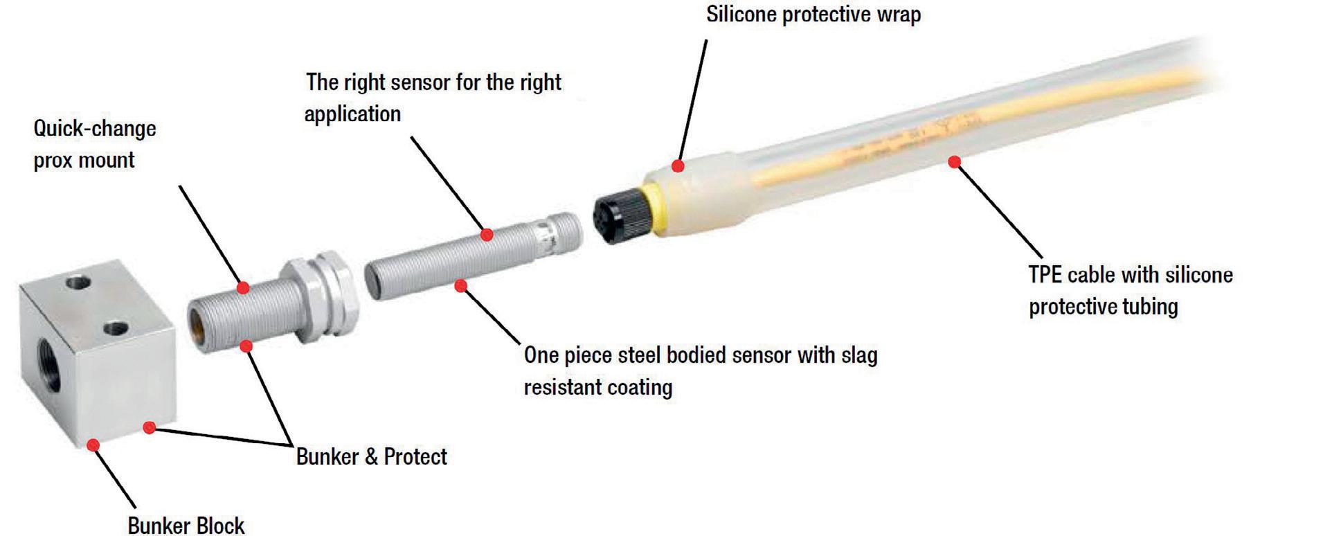
Solution: Protective mounting Don’t use plastic mounts in the weld cell environment. Instead, use bunkered aluminium or steel mounting solutions. Bunkering protects the sensors from impact, and heat. Then, once the sensor and the bunker are protected with silicone wrap, slag build-up will be drastically impeded, increasing the intervals between maintenance as well as decreasing downtime during maintenance.
Photoelectric sensors require attention to perform well in welding environments. Plastic-body photoelectric sensors must be protected from parts loading impact. In addition, just as with a pair of glasses, if the optical lens becomes excessively occluded, photoelectric sensors cannot perform their function. Solution: Choose the right photosensors and protection Choose only robust photoelectric sensors with heat and marresistant lenses. Choose devices with high excess gain properties that can sense through dense weld smoke and debris. Use lens blow-off shields or air knives to create a positive air pressure in front of the sensor, lengthening the time it takes to fog over and reduce frequent maintenance wipedowns. Bunker all photoelectric sensors as you would any inductive proximity type. Avoid fibre optics. Both glass and plastic fibre-optic bundles are frequently broken in welding cells, while one speck of debris and the fibre lens is usually rendered useless.
Vending machines: Detours on the road to productivity
Vending and other dispensing solutions may offer increased convenience, but they do nothing to lower operational costs — in fact, they tend to do the opposite. Vending machines make it easier to sacrifice sensors to a replacement process that actually may be out of control, with little tracking of sensors as to where, why and how often they are being installed. Before even more dispensing machines are installed, get to the root cause analysis of failure and fix the problems first. Worry about supply-chain management after sensor wastage problems have been fixed.
Streamline your storeroom MRO inventory. After you’ve gotten your arms around sensor-related problems, consolidate the number and types of sensors in stores, and weed out what you don’t need or will never use again. How many electrical stores carry totally obsolete sensors and connectors? How many times has the wrong device been installed causing another downtime issue?
How to get started towards a more efficient weld cell production process
Arrange for a thorough weld cell audit. If you’re experiencing what you believe to be heavy consumption of sensors used in your day-to-day welding process, or you believe maintenance time is out of the ordinary, an audit of each individual sensor in every weld cell location may be warranted. In almost every instance, you will dramatically increase production, reduce machine downtime, reduce material and maintenance costs, and increase profitability by integration of even a few of these recommended weld cell improvement methods.
Understand through a documented weld cell audit, how every sensor in every location on the plant floor is performing, where recurrent problems occur and why, and where maintenance people are constantly replacing sensors. Get a handle on the problems and regain control of your processes. Remember, the definition of insanity is doing the same thing over and over again and expecting a different result.
The bottom line
Once you’ve got your sensor problems straightened out, your stores will be current and organised. Resolve to never get into this situation again: on your next weld cell order, be certain that you meet with your most able sensor manufacturer representative and review sensor designs with that individual. Spend a little extra money on the front end for the best bunkering and protection, rapid change-out mounts, application-specific sensors and connectivity systems you can find and you will ensure sensor longevity.
SENSORLESS STANDSTILL MONITOR
The Schmersal SSW300HV is a sensorless standstill monitor developed with a wide-range power supply for all common AC and DC operating voltages, from 24 VDC and 24 VAC to 230 VAC. As a universal device it replaces 14 variants of the previous range, making product selection and spares management simpler. The product is compact at 45 mm wide and has pluggable, coded connecting terminals for rapid, error-free installation, while an additional signalling contact provides information on the error status of the module for control system integration. The operating temperature range is -25 to +55°C, which increases potential installation in harsh locations. The standstill monitor operates entirely without sensors, so no allowance or space is required for mounting external sensors. The safety module is connected directly to a three-phase motor and directly measures the frequency of the induced voltage for rated motor voltages of up to 690 V. The safety contacts open as soon as the motor comes to a standstill. The device can be used in safety circuits up to category 4/PL e in accordance with EN 13849-1 and SIL 3 in accordance with EN IEC 61508.
Control Logic Pty Ltd
www.controllogic.com.au

BULK BAG UNLOADER WITH DUAL SCREW CONVEYORS
Flexicon has released a bulk bag unloader with dual flexible screw conveyors that feed two downstream processes dust-free.
The BULK-OUT BFF Series Discharger features top-mounted receiving cups and a removable bag-lifting frame for forklift loading of bulk bags. Z-CLIP strap holders allow rapid, secure insertion and removal of bag straps from the lifting frame at floor level.
The bulk bag/hopper interface comprises a manual SPOUT-LOCK clamp ring for highintegrity bag spout connections, and a pneumatically actuated TELE-TUBE telescoping tube that exerts continuous downward tension on the clamp ring and bag spout as the bag empties and elongates, promoting flow and evacuation. Additional flow is afforded by FLOW-FLEXER bag activators that raise and lower opposite, bottom sides of the bag at timed intervals into a steep V-shape, and top-mounted POP-TOP extension devices that elongate the entire bag, promoting total discharge with no manual intervention.
The hopper is equipped with dual flexible screw conveyors that transfer free- and non-freeflowing bulk materials to downstream processes separately or simultaneously. The flexible screws are the only moving parts contacting material, and are driven beyond the point at which material is discharged, preventing material contact with seals.
The system is available in carbon steel with durable industrial coating, or stainless steel finished to industrial, food, dairy or pharmaceutical standards.
Flexicon Corporation (Aust) Pty Ltd
www.flexicon.com.au

OUTDOOR CABLES
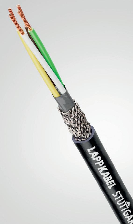
Treotham now offers more LAPP PVC cables for data and signal transmission in the lowfrequency range with a black outer sheath (BK) in its portfolio. This makes them suitable for outdoor use in accordance with DIN EN ISO 4892-2.
The black UNITRONIC LiYY BK has a compact design that enables small outer diameters despite the high number of cores. The classified fire behaviour properties are defined in accordance with EU Directive 305/2011 (BauPVO/CPR). This means that the new black UNITRONIC can be used universally on machine interfaces for many applications for data and signal transmission in the low-frequency range. For example for computer systems, electronic control and regulation devices, office machines or scales. It is suitable for fixed installation or for light mechanical stress and can be used in dry and damp environments.
The LAPP twisted pair UNITRONIC LiYY (TP) BK has short lay lengths so that the conductor circuits are well decoupled. A shielded version — UNITRONIC LiYCY (TP) BK — is also available, which due to its copper braiding protects against capacitive interference from electrical fields with a high degree of coverage.
Treotham Automation Pty Ltd
www.treotham.com.au

Operational technology (OT) comprises the systems, facilities, technologies, supply chains and networks that produce and manage goods and services in critical infrastructure (CI) sectors such as, power, gas, water, food, banking and finance, health, transport, defence, communications and education. These CI sectors provide essential services to businesses, governments and the community, as well as to other critical infrastructure.
They are vital to the social and economic wellbeing of Australia, including public safety and the ability to ensure national security.
A successful cyber attack on critical infrastructure that disrupts the provisions of essential goods and services can put public safety at risk, threaten economic security and, in a worst case scenario, compromise national defence.
In a rapidly evolving threat landscape, CI is a prime target for bad threat actors seeking financial profit via extortion or cyber espionage. But, with high stakes at play, hacktivists and disgruntled insiders are also incentivised to target critical infrastructure.
To build defences against CI threats and mitigate risks, cybersecurity programs of work are vital for OT and CI organisations.
Six key objectives of a cybersecurity program
To achieve a desired state of security maturity, OT organisations should adopt a program of work including six objectives in the security journey: risk assessment, strategy and governance, policy and procedure documentation in line with standards, implementation and security testing, monitoring, and staff training. 1. Risk assessment The program should start with a risk assessment. This assessment should identify all assets in the architecture, assess risk using appropriate terms of reference or standard and have a scoring system to grade impact, likelihood and consequence. Results and findings should be numerically coded and transferred to the enterprise risk register and be nominated at the board’s risk committee meetings. A remediation budget should also be requested. 2. Strategy and governance The strategy and governance documentation should take the results of the risk assessment and list the major projects the organisation must complete to mitigate or remediate identified risks to an acceptable level. This documentation should include projects, funding and timelines. 3. Documentation Organisations should create security policy, procedure and architecture documentation referencing an appropriate architectural model.
An ISMS can be built by the selection of a standard such as ISO/IEC 27001:2013, ISA/IEC 62443, NIST or the Australian Government Information Security Manual. Standards contain cybersecurity domain and controls that once implemented enable an organisation to achieve a strong cybersecurity posture. 4. Implementation and testing The implementation phase of a security architecture builds and tests the specified architecture in its physical form in four phases: • Proof of concept (POC) • Factory acceptance testing (FAT) • Site acceptance testing (SAT) • Security testing with active and passive penetration testing of security controls 5. Monitoring and incident response Monitoring and incident response planning confirm system visibility and alerting capability across architectures for operational and security events based on a series of rules.
It is advisable to collect key metrics from devices across the architecture to enable monitoring and reporting across four key areas: operations, applications, security and business objectives. 6. Training Training is a critical step in the security program to impart knowledge and help build a security culture. The main two training types are: cybersecurity awareness, which covers basic security concepts, and training on policy documentation established in the documentation and architecture phase.
OT organisations should adopt a cybersecurity program of work that identifies the organisation’s critical assets, assesses and documents risk, and maintains a risk register with remediation plans.
The security program should document the people, processes and technology of the operational architecture in line with appropriate standards. It should also warrant competent implementation with active and passive testing. While visibility of the architecture is key to incident response, cybersecurity awareness and policy training are imperative to building a strong security culture.
A robust cybersecurity program built on the six key objectives will enable a strong cybersecurity posture and compliance with the impending changes to the Critical Infrastructure Act.
6 STEPS
TO DEVELOP A CYBERSECURITY PROGRAM FOR OT
Andrew Sheedy, Director OT Security Solutions, Fortinet


