13 minute read
How BizAv’s Top Engine OEMs are Cutting Emissions
With a growing emphasis on sustainability in BizAv, engine OEMs are focusing on reducing CO2 emissions, polluting oxides of nitrogen, and environmental noise from their Business Aviation engines. Chris Kjelgaard explores how…
With large sectors of the aviation industry having set themselves a 2030 goal for achieving net carbon neutrality, and the entire industry adopting a 2050 target for achieving zero carbon emissions, all major manufacturers of turbine engines are working intensively to reduce the emissions of greenhouse gases from their powerplants.
Advertisement
They’re working just as hard to reduce the levels of environmental noise their engines produce.
The design and performance criteria for BizAv engines differ from those for commercial aircraft powerplants, however. Business Aviation operators mainly want their aircraft to fly faster and higher than airliners, but retain high dispatch reliability. For airliners, fuel-efficiency and engine reliability at very high daily utilization rates are vital.
Nevertheless, the environmental imperatives facing the huge scheduled airline sector apply equally to the Business Aviation industry. Both high-profile aviation sectors are under tremendous public pressure to become more environmentally friendly and make their businesses more climate-sustainable.
So, the impetus for manufacturers of Business Aviation turbine engines to reduce the levels of environmentally harmful emissions from their engines is just as great as for OEMs of commercial aero engines.
In most cases, the companies which make the highestselling BizAv engines are the same ones which make the highest-selling commercial engines, so much of their R&D work on reducing emissions can be applied to their BizAv and commercial engine lines alike.
Very simply, the more resourceful a turbine aero engine is in terms of its propulsive and thermal efficiency, the lower the levels of CO2 and other greenhouse-gas emissions it creates, compared with less-efficient engines of equivalent power. That’s because those engines will burn more fuel to achieve the same power output.
For engineers designing modern turbofan and turboprop engines in Business Aviation, this (in practice) means the hotter the core section of the engine in which the air is compressed, mixed with fuel, combusted, and exhausted can run, and the smaller the core is in relation to the amount of secondary bypass air the fan or propellers create, the more efficient the engine will be.
Looked at another way, the higher the engine’s operating ratio (the amount of bypass air accelerated by the fan or propellers to produce most, or all the engine’s thrust or power, divided by the amount of air passing through the engine core), the greater the engine’s efficiency becomes.
This has enormous implications for the aerodynamic designs of the engine’s parts and the materials from which the parts are made. “Materials that withstand increased operating temperatures and higher stresses, at lower overall weight, are key differentiators,” says Edward Hoskin, Vice President, Engineering for Pratt & Whitney Canada.
Photo Courtesy of Rolls-Royce

“For turboprop corporate aircraft, the propeller efficiency is already operating close to the theoretical peak, making thermal efficiency the most powerful driver on fuel burn.”
Superalloys and Wizardry
Even though modern turbine blades are made of highly heat-resistant, advanced nickel superalloys, the combustor and turbine stages of modern commercial and BizAv turbine engines are exposed to exhaust gases of temperatures high enough to melt the high-pressure turbine blades.
The only reason they don’t melt is design and engineering wizardry in the forms of intra-blade and bladesurface cooling techniques, using relatively cool air diverted from the engine’s compressor stages, and running it through complex 3D air pathways inside each blade. Protective thermal barrier coatings are also applied to the surfaces of the blades.
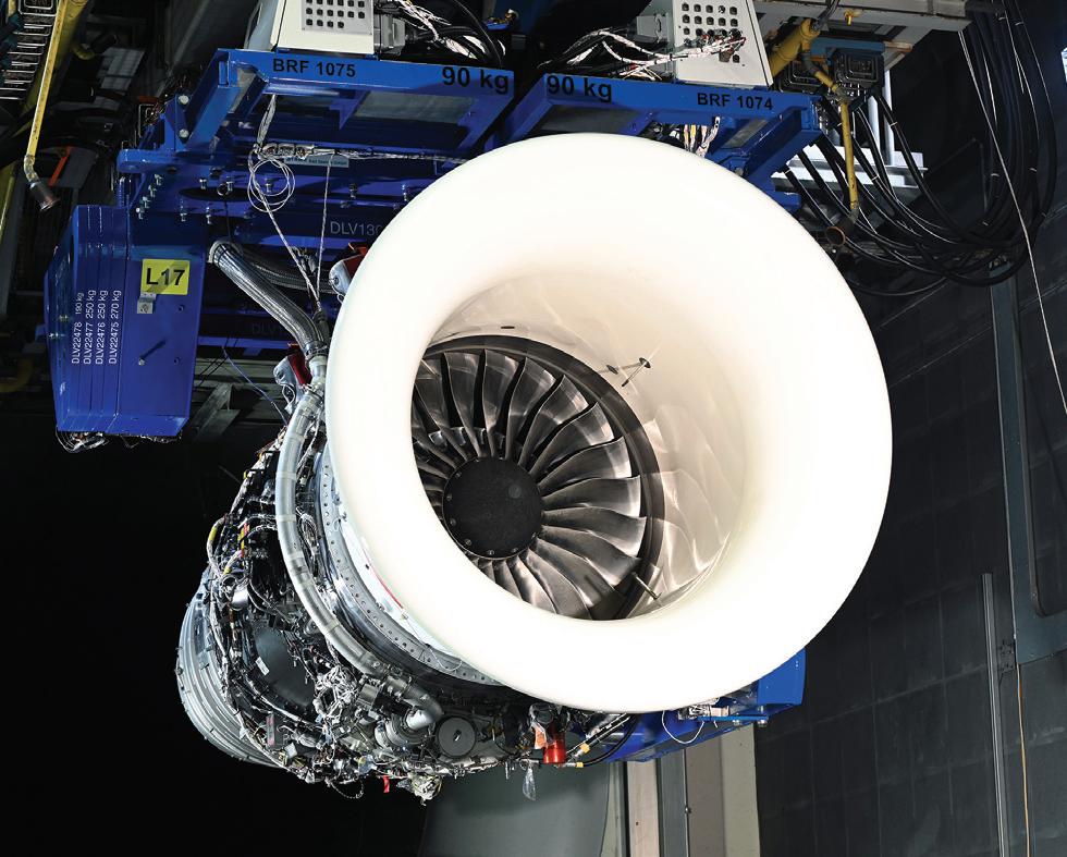
Each engine OEM has its own proprietary recipes for the blade thermal barrier coatings it employs, and they are among the most closely held commercial secrets of each. Rolls-Royce’s latest, most advanced BizAv turbofan engine family is the Pearl, the next generation from the BR725 (which powers the Gulfstream G650) using a new, advanced core design first tested by Rolls-Royce in its Advance 2 demonstrator engine. Thanks to its small powerful core and thrust capability, the Pearl family has a bypass ratio (of bypass air to core air) of up to 6.5-to-1 and an overall pressure ratio of nearly 50-to-1. Both ratios are among the highest found in the Business Aviation industry, helping optimize the Pearl family for fast subsonic flight and high operating altitudes. In fact, the Pearl 700 is 5% more fuel-efficient over the course of its operating lifetime than its predecessor, which would translate into a Pearl 700 burning one million liters less fuel when installed on a comparable aircraft, according to Colm Golden, Senior Vice President of the Rolls-Royce Pearl 700 Program. “In my view, the most important materials in the Pearl are its single-crystal turbine blades and vanes as they allow the engine core to be operated at extremely high temperatures, reaching nearly 2,000° Kelvin (3,140F)," Golden says.
As its name implies, each single-crystal Pearl highpressure turbine blade is created as a single crystal of a proprietary nickel superalloy.
Ceramic Matrix Composites
Such superalloys remain the state-of-the-art in production turbine blades, but each major engine OEM is studying how and where in its engines it might be able to make most use of a new class of very lightweight, very strong, very heatresistant advanced materials called ceramic matrix composites (CMCs).
According to James Hoare, Senior Director of Engineering in Honeywell Aerospace’s Propulsion Engineering Group, research to date indicates that for Honeywell, CMCs would “make sense in reducing secondary-flow parasitics” — which in many cases are a necessary feature of turbine aero engine design but also are an important contributor to reducing engine efficiency.
Secondary parasitic flows are airflows within the engine that do not contribute to driving the engine’s high-pressure turbine shaft or producing thrust.
One typical, but to date necessary, secondary parasitic is the airflow diverted from the engine’s compressor to cool the interiors and surfaces of its turbine blades. Another is air similarly diverted to provide a boundary cooling layer between the interior of the combustor and the tiles from which its interior lining is made.
Today, without such parasitic flows turbine aero engines wouldn’t work. Tomorrow, however, were certain metal or alloy parts in the engine replaced by parts made from suitable CMC material which could withstand higher temperatures, some secondary parasitic flows of air or exhaust gas could be removed, and engine overall operating efficiency would be increased.
In fact, GE Aviation — which has tested CMC turbineblade stages extensively in a demonstrator military turbofan engine of the type used to power the F/A-18 Super Hornet — thinks the most promising use of CMCs might be in highpressure turbine blade stages, replacing stages made of nickel superalloys and doing away with the parasitic air flows needed to cool metal-alloy blades.
Other Emissions-Reducing Techniques & Materials

Manufacturers make use of many other techniques and materials in designing their engines for increased efficiency and lower emissions levels.
One major way OEMs increase the efficiency of their engines (thus reducing emissions) is by using modern materials and manufacturing methods to replace, with onepiece parts made of strong but light metal materials, components within the engine that were traditionally comprised of multiple parts — such as compressor blade stages, and the fan at the front of the engine.
Not only are such components lighter and in many cases stronger, more durable, and efficient than their multi-part predecessors, they’re also easier and cheaper to maintain and replace during a repair. They greatly reduce the operator’s or maintenance facility’s parts inventory storage requirements, reducing overall operating costs, too.
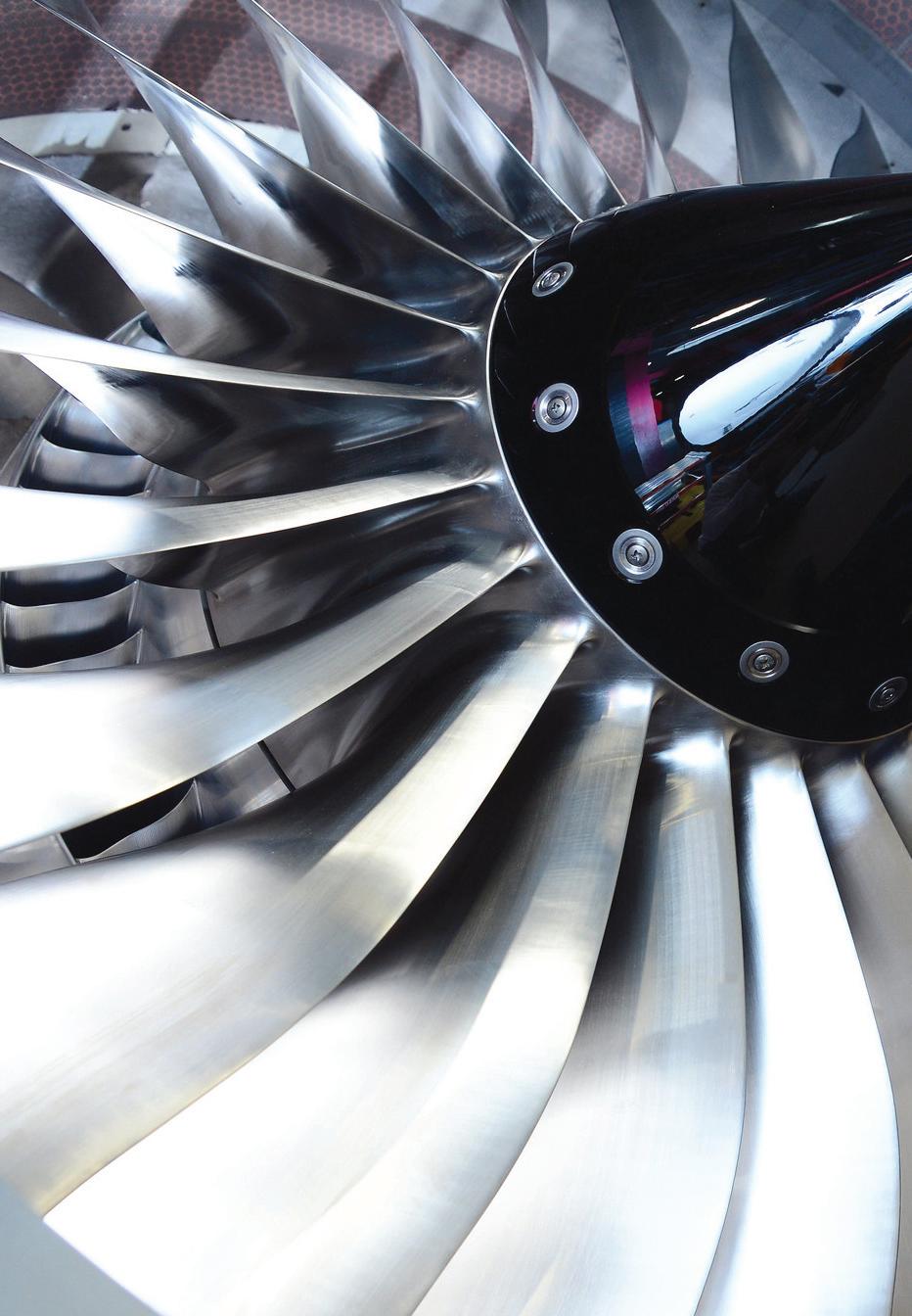
Most engine OEMs use the term “blisks” (short for bladed disks) for the one-part rotating blade stages they have developed for their engines. According to Golden, six of the ten high-pressure compressor blade stages in the Pearl engine family are blisks, and for the first time in any Rolls-Royce engine the Pearl’s fan (the large fan at the front of the engine producing the bypass air which provides most of the Pearl’s thrust) is a one-piece blisk, made from titanium.
Composite materials, typically made from very strong, but very light carbon fibers embedded in resin matrices for aerospace use (formally known as carbon fiber reinforced plastics - CFRP), are also seeing wide use in turbine aero engine manufacture.
The most important use of CFRP composites to date for BizAv engines is as the strong but light materials from which the fan casings and nacelles of various engine types are made. Potentially an important future use for BizAv engines could be for fan blades and disks.
Although no Business Aviation aircraft yet has a CFRP fan, commercial-engine manufacturer CFM International — the world’s largest producer of jet engines — and GE Aviation, one of CFM’s two joint-venture equal partners along with Safran Aircraft Engines (which developed the technology), have long employed carbon-fiber fans in their big turbofan engines for airliners.
Each major manufacturer today has one or more patented combustor designs which mix and ignite the air/fuel mixture inside the combustor in ways which minimize the creation of oxides of nitrogen (NOx), which pollute the air and act as greenhouse gases. These ultra-low-emissions combustors typically make the fuel/air mix leaner (more air, less fuel) as it’s ignited.
Photo Courtesy of Rolls-Royce
Additive Layer Manufacturing of Parts
In commercial and Business Aviation engines, each of the major engine manufacturers now employs parts made using additive layer manufacturing (ALM), more commonly known as 3D printing. Honeywell already uses a variety of ALMmanufactured parts in its TPE331 turboprop and HTF7000 turbofan BizAv engines, as well as in several of the auxiliary power units (APUs) it makes.
The numbers and functions of ALM-constructed parts are only likely to increase as ALM manufacturing techniques and efficiencies continue to develop, according to Hoare.
Today there are two main uses for aero engine parts made by ALM.
First, and probably still the most common use, is to make one-piece parts of complex shapes to supersede parts. Fuel injection nozzles represent one such example. As ALM quantitative-manufacturing capabilities grow, it’s becoming cheaper and easier for engine OEMs to use ALM to make large numbers of one-piece parts.
The second use, partly related to the first, is to create one-piece parts with topologies previously not possible to
manufacture at all using traditional forging and casting techniques, according to Hoare. Creating parts with highly complex internal topologies can produce significant operational benefits and efficiencies for an engine.
For instance, Rolls-Royce uses ALM to make each of the tiles lining the interior of the Pearl’s ultra-low emissions combustor. According to Golden, using ALM allows RollsRoyce to design more complex 3D cooling-air internal pathways (including 180 degree bends and having fan shaped holes) than traditional manufacturing techniques. This enables much more efficient combustion and hence allows the core temperatures to be increased. In addition to improving the durability of each tile, the protective cooling air reduces the amount of NOx created by the igniting of the fuel-air mix inside the combustor, improving the engine’s environmental performance.
Honeywell is studying a similarly environmentally beneficial potential use for ALM-made parts in the linings of engine nacelles, says Hoare. It may be possible to reduce engine external noise by creating pathways in the internal lining in which engine exhaust gas can inter-mix with bypass air to cool the hot exhaust before it exits the nacelle, and also dissipate or attenuate acoustic energy in other ways.
“The gains from additive manufacturing are largely related to cost and efficiency of manufacture, but they do contribute to improved engine efficiency and weight savings,” says P&WC’s Hoskin.
“For example, additive manufacturing of certain parts may allow for thinner walls compared to equivalent cast parts, and heavier steels can be replaced by lighter materials like titanium. Also, castings that have complex internal passages could benefit from improved parasitic losses, although these improvements are very small in magnitude.”

Engine Integration & Aircraft Mission Profile
There are other important considerations for BizAv engine designers when seeking to improve engine efficiency and reduce environmental emissions.
For example, the importance for overall engine operational efficiency of the aerodynamic and structural integration of the engine with the intended airframe. “For both turbofans and turboprops, engine integration and installation on the aircraft play a key role in optimizing engine performance across all phases of flight,” says Hoskin.
Integration of the engine and nacelle includes the position in which the engines are mounted on the aircraft, particularly for business jets designed to cruise at high subsonic speeds and at high altitudes, according to Hoare.
Business jets typically are configured to have their engines mounted at the back of the aircraft, high on the fuselage near the vertical stabilizer, in order to minimize the amount of engine noise experienced in the cabin. For different aircraft types, “How does that impact the system and the mission?” he asks.
Designers also have to optimize each engine type for the typical mission profile envisaged by the aircraft OEM — a decision which often influences their choice whether to offer an airframe manufacturer a turboprop engine or a turbofan engine for a given aircraft type. No one would think of powering the Gulfstream G700 with a turboprop engine, for instance — or install Pearl engines on a Twin Otter.
“Turboprops inherently have high bypass ratios,” in the 50-to-1 to 100-to-1 range, says Hoare. “They are very efficient,” their large propellers producing enough bypass air to ensure that turboprops operate at nearly the theoretical limit of their propulsive efficiency throughout each flight.
Turboprops are ideal for operating at “lower altitudes, on smaller aircraft, and they’re best suited to short hops,” he says. The exhaust gases from turboprop engines produce little, if any, measurable contribution to the powerplant’s overall thrust.
Turbofans, on the other hand, produce some of their thrust from the hot gases exhausting from their cores, though in today’s BizAv turbofan engines most of the thrust is produced as cold bypass air by the large fan at the front of the engine.
Turbofan engines are suited to operating at faster cruise speeds and higher cruise altitudes, but offer less propulsive efficiency than turboprops. Both categories of engine can realize performance gains from improved thermal efficiencies.
Photo Courtesy of Honeywell
In Summary
Today’s Business Aviation engines, turbofan and turboprop, are technological marvels which incorporate cutting-edge advances in many fields of science and technology.
Materials science, aerodynamics, thermodynamics, manufacturing technologies, information and digital control technologies (to be discussed in the June edition of AvBuyer), predictive data analytics, computer-aided design, acoustics, meteorology, environmental sciences, and satellite and cellular telecommunications are some of the areas of scientific endeavor relevant to the design and operation of Business Aviation’s leading powerplants.
Neither the turboprop nor the turbofan is inherently

superior in operation to the other type of engine—both are classes of gas turbine engine, optimized for different jobs and often different wallets. A third class of turbine engine, the turboshaft, is optimized for powering rotorcraft.
However, the day is likely to dawn within the next 20 years when a new class of turbine engine – the open fan or open rotor – will marry the high propulsive efficiency of the turboprop to the high thermal efficiency of the turbofan to create a more environmentally-friendly engine capable of efficiently powering business aircraft and commercial aircraft alike.
Today, typified in the Open Fan design being developed in CFM International’s Revolutionary Innovation for Sustainable Engines (RISE) R&D program to study potential next-generation turbine engine configurations, propulsion methods and fuel sources, the Open Fan could offer bypass ratios as high as 75-to-1 (CFM’s goal) while offering thrust levels capable of powering the largest business and commercial aircraft. ❚ More information from: GE Aviation: geaviation.com Honeywell: aerospace.honeywell.com Pratt & Whitney Canada: pwc.ca Rolls-Royce: rolls-royce.com
CHRIS KJELGAARD


