
2 minute read
stepper and brushless dc motors
For engineers and designers working on modern-day motion and other industrial applications, it’s vital to understand the advantages and disadvantages of stepper and brushless dc (BLDC) motors. Here we’ll look at a widely used hybrid stepper motor and a 3-phase BLDC motor and compare both devices. We’ll consider the working principles of these motors (physical size and power density) and make observations about the acceleration and noise aspects of each motor. Experiments performed under various load conditions reveal changes in power, e ciency, and temperature.
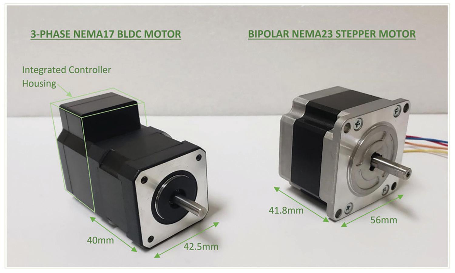
The key dimensions of the EZmotion MMS742038-24-R1-1 BLDC motor and a general-purpose stepper motor used in the test setup are shown here.
Stepper motors
Most widely used stepper motors are hybrid stepper motors, which consist of permanent magnet rotors and electromagnet stators. Rotors have two cups with permanent magnets; one with north poles, and a second with south poles.
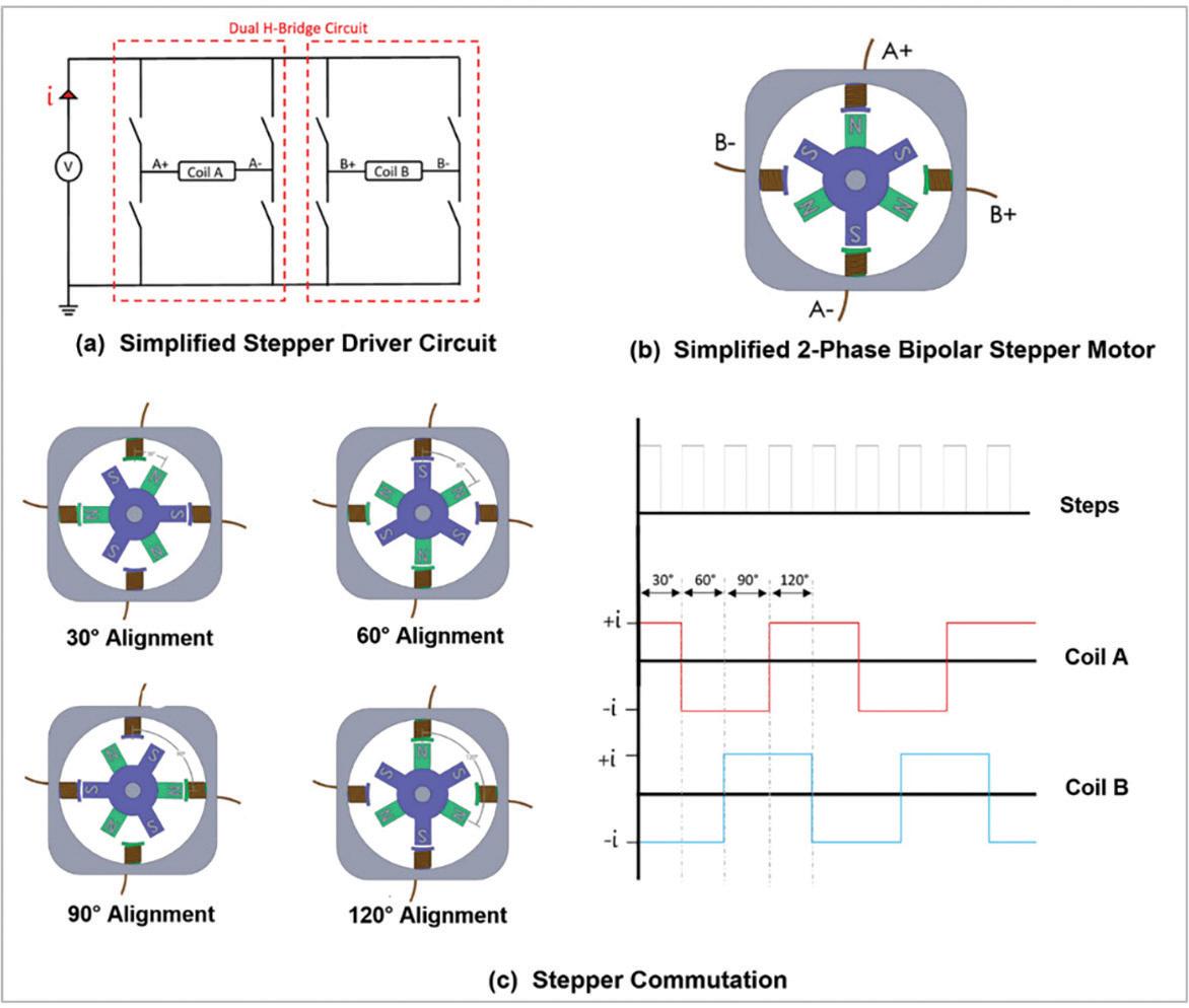
A simplified stepper motor has a rotor made of two cups of permanent magnets. Each cup has three teeth with a respective magnet pole. In this case, these cups are assembled such that they are out of phase by a half-pitch (60°). The stator consists of four poles with two phase windings.
Steppers are electronically commutated. According to step input pulses, the bipolar stepper driver uses a dual H-bridge circuit to energize the stator poles in a sequence that allows the rotor to rotate by a step angle. The step angle can be calculated with the following equation:
Step Angle (in °) = 360/(2 x (n_ROTORTEETH) (n_PHASE))
For each step pulse, the rotor rotates 30° — this stepper is known as a 12 full-step stepper motor. During full-step operation, the commutation sequence and rotor position follow a particular sequence. Most stepper motors on the market have 50 or 100 pole pairs, with 200 or 400 full steps for one full rotor revolution. This makes the step angle as small as 1.8° or 0.9°.
With an advanced stepper motor driver, this small step angle can be further divided into even smaller angles by implementing microstepping operation. The step angle can be reduced by a half-step, quarter-step, and up to a 1/256 step. Stepper motors o er superior positional accuracy because they can step by such small angles.
The graphics show the simplified working principles of hybrid bipolar stepper motors.
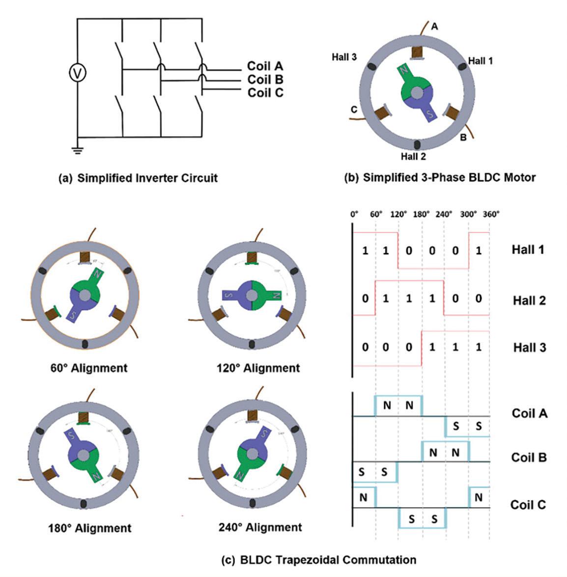
Here, the working principles of a BLDC motor and a simplified single pole pair 3-phase BLDC motor (denoted as (a) and (b) in the figure respectively) are shown.
Brushless dc (BLDC) motors


Brushless dc motors have a permanent magnet rotor and electromagnet stator and require electronic commutation. To commutate brushless dc motors, the instantaneous position of the rotor is required. To meet this requirement, Hall-e ect sensors are used to realize the rotor’s angular position. This information is fed to a microcontroller (MCU) that switches the phase winding current using the 3-phase inverter circuit. Essentially, the dc input voltage is converted to 3-phase ac voltage to sequentially energize the stator poles using an inverter circuit.
The rotor magnetic field always chases the stator magnetic field, which results in the motor spinning. Because the simplified motor is a single pole pair BLDC, each commutation step is 60 electrical and mechanical degrees. BLDC trapezoidal commutation and the rotor position can be obtained. However, typical trapezoidal commutation makes the motor susceptible to torque ripple. As a result, an advanced commutation technique called field-oriented control (FOC) is used on the motor for testing. FOC provides minimal torque ripple and smooth motor operation.
Experimental set-up

Stepper motor test
To set up the stepper motor test, a NEMA 23 bipolar stepper motor is used along with a magnetic particle brake for load simulation. The motor test requires five main components described below:
• An encoder (mounted on the particle brake’s other end) monitors the shaft’s rotational speed.


• A bipolar stepper motor driver — featuring parallel inputs, internal current sensing, and regulation — controls the stepper motor.
