6 minute read
VFD control methods
In the first of this two-article series, we considered VFD operation types to satisfy process and motion-control applications. Here we delve deeper into two advanced types of operation.
Lisa Eitel | Executive editor
Brushless AC (BLAC) motors are driven with sinusoidal AC currents and (due to skewed magnets and sinusoidally distributed windings in their stators) also produce sinusoidal back EMF. Sinusoidal commutation is a common way to control BLAC motors, as it provides a very consistent torque output with little torque ripple. But at high speeds, sinusoidal commutation begins to sacrifice motor e ciency.
Another method called field-oriented control (FOC) or flux-vector control also generates sinusoidal waveforms and produces consistent torque … and it yields better motor e ciency, especially at high speeds.
Precise vectorbased modes of VFD operation are often useful in advanced conveyor applications.
| Itsanan Sampuntarat
Shown here is a block diagram of field-oriented control with space vector pulse width modulation. The goal of FOC is to align the stator current vector to be orthogonal (90°) to the rotor flux.
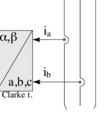

Kirchho ’s current law states that at any junction in an electrical circuit, the sum of currents flowing into the junction is equal to the sum of currents flowing out. In the case of a three-phase motor, Ia + Ib + Ic = 0. So if two currents are measured, the third must be the negative sum of the first two to maintain a zero sum of the three.
Sinusoidal motor commutation


Torque output in any motor is maximized when the stator and rotor magnetic fields are orthogonal at 90° to each other. Sinusoidal commutation works to generate a rotating current vector with a constant magnitude and direction that is orthogonal to the rotor. Recall that vectors have both magnitude and direction.
To achieve this, two of three stator phase currents are generated 120° phase-shifted from each other based on rotor position, which is provided by an encoder. The third is determined using Kirchho ’s current law. The result is a smoothly rotating current vector with constant magnitude that is always orthogonal to the rotor.
Sinusoidal commutation provides smooth motion with very little torque ripple. But as motor speed increases, e ciency deteriorates. This is because with increasing speed, the frequency of the sinusoidal current command signals also increases, making it di cult for the current loop controllers to track the command signals. In addition, as speed increases, motor back EMF increases in frequency and amplitude. The result is phase lag between the stator and the rotor, taking the current vector out of the optimal 90° alignment with the rotor flux. This reduces the torque produced for a given current and decreases the motor’s e ciency.
Where sinusoidal commutation is based on a three-phase system that is dependent on time and speed, field-oriented control transforms this system into a two-coordinate system — d and q — that is not dependent on time … similar to that of DC control. There are two inputs to FOC:


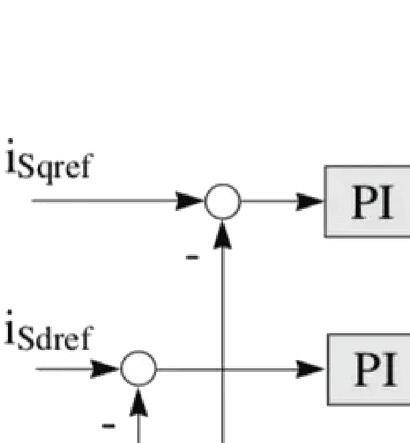
Field oriented control transforms a threephase, time-dependent system into a twocoordinate (d and q) time-invariant system. SVPWM is used in the final step to determine the PWM signals to be applied to the motor.

• The torque component (aligned with the q coordinate) and
• The flux component (aligned with the d coordinate).
First, in a manner similar to sinusoidal control, the current in two windings is measured (recall that current in one of the windings is not controlled. It is the negative sum of the current in the first two windings). Then, a Clarke transform is used to convert the three axes of current into a two-axis system. The resulting two-phase waveforms have the same amplitude as the original three-phase waveforms.
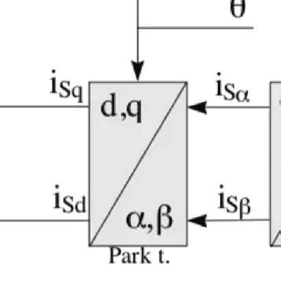
Next, a Park transform is used to convert the two-axis system from a fixed reference to a rotating reference frame that is in synchronization with the rotor flux. The result are the d and q values. The d axis current is aligned with the rotor flux, and the q axis current is orthogonal to rotor flux. Because it is orthogonal to the rotor flux, the q axis current is responsible for torque production. In other words, torque is increased by increasing the q axis current and decreased by decreasing the q axis current.
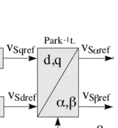
A separate PI controller is used for each axis, d and q, to read current error signals and amplify them to produce voltage to the motor. But because the voltages are on a rotating reference, an inverse Park transform is performed, which converts them back to a stationary reference frame. An inverse Clarke transform is then performed to convert the two voltages back into three values so they can be applied to the three motor windings.
While field-oriented control seems more complex on the surface (and admittedly, it is more mathematically intensive), the decreasing cost of processing technology makes it a viable solution for many motion control systems. On the other hand, sinusoidal control is the preferred choice for simple, low-cost control of brushless motors.

Basics of space-vector pulse-width modulation (SVPWM)
We’ve now reviewed how one common modern method for controlling three-phase induction motors and permanentmagnet synchronous motors (also called BLAC or PMAC motors) is field-oriented control — a technique that independently controls the magnetizing and torque-producing components of the stator current. This allows the torqueproducing component to be kept orthogonal to the rotor flux … maximizing torque production.
Space vector pulse-width modulation (SVPWM) is a technique used in the final step of field-oriented control to determine the pulse-width modulated signals for the inverter switches to generate the desired 3-phase voltages to the motor. The following is a summary of how FOC with SVPWM operates.
1. Measure two of the three motor phase currents and feed them into a Clarke transform to convert them from a
Motion Control
For each leg of the inverter output, either the top transistor will be open (and the bottom closed) or viceversa. Therefore, there are eight total states (23) for the inverter output.
three-phase system (ia, ib, ic) to a twodimensional orthogonal system (iα, iβ). Note that it’s not necessary to measure all three currents because the sum of the three must equal unity (0). So the third current must be the negative sum of the first two.
2. Apply a Park transform to convert the two-axis stationary system (iα, iβ) to a two-axis rotating system (iq, id) where the d axis current is aligned to the rotor flux and the d axis current (the torqueproducing component) is orthogonal to the rotor flux.
3. The stator current flux and torque are independently controlled — typically by PI controllers. Voltages to be applied to the motor Vd and Vq are determined from the PI controllers.
4. Next, an inverse Park transform converts the two-axis rotating system (Vsqref, Vsdref) back to a two-axis stationary system (Vsαref, Vsβref). These are the components of the stator voltage vector and are the inputs for the SVPWM, which generates the 3-phase output voltage to the motor. (Note that the use of SVPWM eliminates the need for an inverse Clarke transform to obtain the three-phase output voltages.)

The details behind SVPWM
Voltage is delivered to the motor by a three-phase inverter with six transistors (two on each leg of the output). Each of the three outputs can be in one of two states (top transistor closed and bottom transistor open, or vice-versa), giving eight (23) total states for the output. These are called base vectors.
The values of T1, T3, and T0 can be determined with the equations shown here. Then a simulation of Vout can be expressed as shown.

The eight base vectors are plotted on a hexagonal star diagram. Each vector makes up a spoke of the star, with 60° phase di erence between adjacent vectors. The two vectors V0 and V7 that contain outputs which are either all plus or all minus are called null vectors and are plotted at the center (origin) of the star.
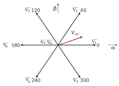
Each base vector makes up one segment of a hexagonal star with the null vectors V0 and V7 plotted in the center. The goal of SVPWM is to produce a mean vector during the PWM period (TPWM) that is equal to the desired voltage vector Vout.
The location of Vout is determined on the star diagram, and the base vectors that constrain that sector (V1 and V3 for example) along with one of the null vectors, are used to synthesize the desired voltage. This is done by applying V1 for a specified time T1 and V3 for a specified time (T3) and the null vector for the time necessary (T0) to provide a resultant vector equal to Vout.
Compared to standard field-oriented control, using FOC with space vector pulse width modulation enables more e cient use of the DC supply voltage and provides lower harmonic distortion; the latter, in turn, improves the power factor … and reduces torque ripple. DW
Motion Control Tips | motioncontroltips.com
Medical Molded Cable Assemblies


Turn your design challenges into next-generation, marketleading medical devices with our extensive manufacturing capabilities and engineering expertise. We have facilities in Fremont, CA and Santa Ana Sonora Mexico.
WHAT DO YOU THINK?


