3 minute read
Hydraulic manifolds
In simplest terms, a manifold is a component from which you attach other things. A slightly less elementary explanation is that it cleans up plumbing — and this is why you should care about this unassuming block of metal that ultimately makes for smoother system design.
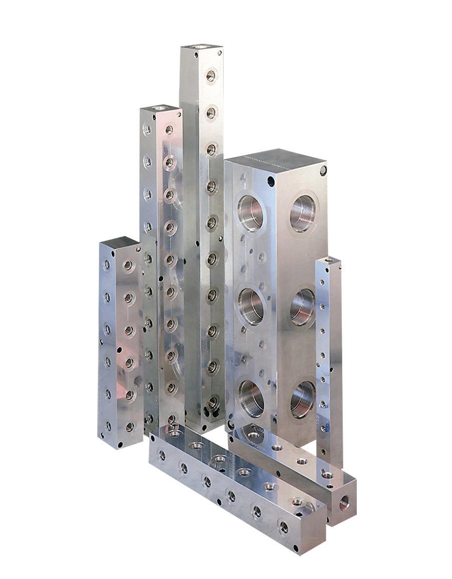
A hydraulic manifold is a housing for surface and/or cartridge valves that regulates fluid flow between pumps, actuators and other components in a hydraulic system. It can be compared to a home’s electrical panel. Just as raw electrical power comes to the panel and is distributed to various household circuits to do work (provide light, power the dishwasher, operate the garage door), hydraulic oil under pressure is routed to the manifold by a pump where it is diverted to various circuits within the manifold to do work.
The role of a manifold is to bring the hydraulic circuits to life through the creation of a block machined in a manner consistent with the original circuit design. All valves have a series of orifices to which drilled holes in the manifold must communicate. The configuration of these drilled holes in the manifold is the representation of the defined circuit.

Image courtesy of Daman
The manifold is the central muscle control of the hydraulic system receiving inputs from switches, manual operations (levers) or electronic feedback systems. These inputs energize various valves mounted on or in the manifold, while specific oil pathways allow oil to flow through hydraulic lines to the appropriate actuator to perform work. The complex matrix of variables can make manifold design and component selection a challenging and rewarding art form, as size, weight, function, performance and operating environment are always part of the design consideration.
In addition to providing a neat and logical layout, consolidating components into a manifold reduces space and pressure drop. This results in fewer fittings, more efficient assembly times and reduced leak points. Manifolds are sometimes viewed as black boxes, as they can be highly complex with upward of 500 holes communicating with each other and many valves on a single block. The alternative to manifolding a system is to mount all valving in individual blocks and plumb hoses in a manner consistent with the circuit. This dramatically increases the visual nature of the system, introduces infinitely more leak points and is generally an unacceptable alternative to manifolds. If a system is properly designed and test points are provided in key locations, finding a problem becomes much quicker and simpler with a manifolded system. If transducers and other data collection devices are connected to these test points, the data may be linked into the machine controller and operation’s terminal displays.
Manifolds generally operate within 500 to 6,000 psi operating pressures. With additional design considerations, 10,000 psi can be achieved within the scope of steel and stainless-steel manifold designs. Although not typical in hydraulic application, 50,000 psi can be achieved with special materials and design nuances. Manifolds come in three basic types. Most common is a solid-block design that contains all drilled passages and valves for an entire system. Typical materials for solid-block manifolds are aluminum, steel and ductile iron. Block weight can reach 100,000 lb.
Modular-block, or stackable design, is a subset of the drilled block. Each modular block usually supports only one or two valves and contains interconnecting passages for these valves as well as flow-through provisions. It normally is connected to a series of similar modular blocks to make up a system. This system is known for its flexibility within a limited range of circuit complexity. Modular block designs are generally held together with tie rods or a system of tapped holes that allows for machine screw connections.
Lastly, laminar manifolds complete the manifold category. Laminar manifolds are usually made of steel, with passages milled or machined through several plates of metal. These plates are stacked or sandwiched with the various fluid paths determined by the shape of the machined passages. Solid-metal end pieces are added, and the whole stack is brazed together. Internal passages can be cut to any shape needed, so nearly any flow rate can be accommodated with minimal pressure drop.
Laminar manifolds are always custom-designed. Valves and other connections can be located where appropriate for a specific application. But because of the permanently shaped flow passages and brazed construction, this type of manifold cannot be modified easily if future circuit changes become necessary.
Because there are so many configurations available for manifold design, there are several software packages available to help the engineer design a system. With advances of these design software packages and CNC technology, the installed cost for custom solid-block manifolds, even small runs, is highly competitive to systems using modular blocks or discrete components.


