5 minute read
Stages, rotary tables, and gantries take application-specific iterations


Motion designs today must offer simplicity in setup and startup,which is why component suppliers execute more integration thanever of positioning stages, rotary tables, and gantry setups for OEMs and plant engineers. Most of these solutions include all the axes’ motors and drives as well as the controller for quickly electrical andmechanical connection — and easy networking to other machines as well as supervisory control systems such as PACs. Of course, increased need for networked controllers and drives has come with ever-faster communication protocols such as Ether CAT.
Other manufacturers leverage the power of automation controllers designed to control axes of motion as well as the rest of the machine. These accept all I/O for seamless control of whole operations — which relieves OEMs and plant engineers of the integration burden.

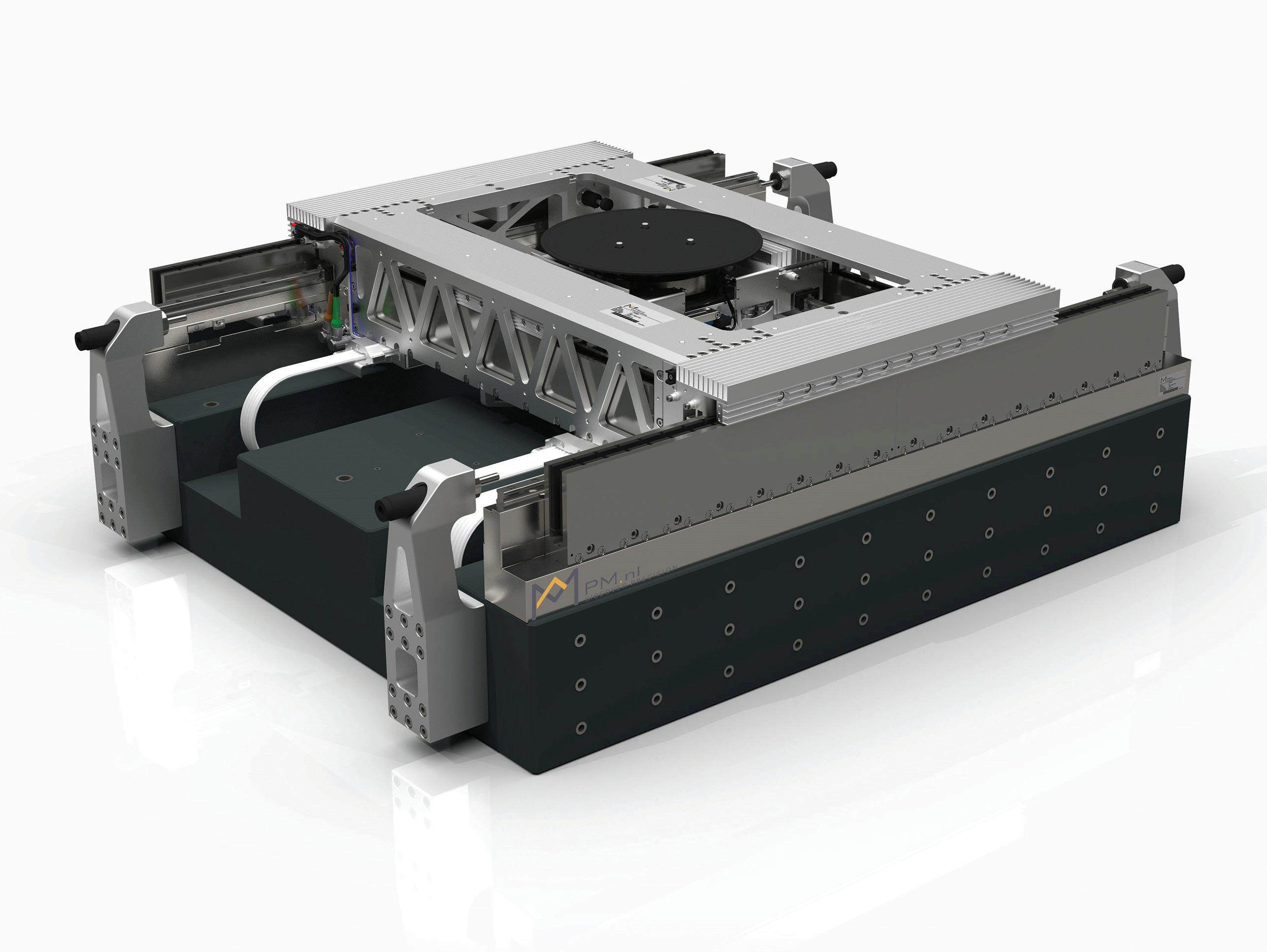
The Vega semiconductor backend inspection machine owes its high accuracy to the fact that all centers of gravity and driving forces go through one plane. PM engineers used their linear-bearing expertise and knowledge from the production floor to perfect the motion system.
XY2Z-THETA MOTION SYSTEM SPEEDS SEMICONDUCTOR WAFER INSPECTION
For more than fifty years, the Dutch linear-motion company PM has developed and produced precision linear and rotating bearings and slides. It focuses on applications requiring smoothness and stiffness from their linear bearings … and continues to expand its standard range of linear components. But customization is becoming the norm — and now, catalog products account for only around 30% of sales. Customization usually begins with the machine builder asking for slight changes to some standard component — for just a bit more precision or a smaller footprint or an additional mounting option, for example. 30% of PM’s business is here.
The final third of PM’s business is in supplying ultra-precise positioning solutions. That’s in part because very few end users consider such designs to be their core competency. Here, PM collaborates with customers to build motion systems … and continually works towards projecting the design features likely to be required by industry over the next five years. One design to come of the latter efforts is called the Vega motion stage … a key subsystem in the manufacturer’s XY2Z-theta motion system for backend wafer inspection applications.
“The semiconductor industry is very demanding,” says PM manager of R&D and engineering Jan Willem Ridderinkhof. “So our logic is that if we can perform in that industry, we should also be able to satisfy the medical market.”
HIGH SEMICONDUCTOR THROUGHPUT GENERATES A LOT OF HEAT
Over a stroke of more than three hundred millimeters, mechanical accuracy in the X and Y directions must be better than 1 µm at accelerations of 2 g and speeds to 2 m/ sec. Vibrations in that plane must remain below 25 nm. Vibrations in the Z axis — used to get the wafer into the optics’ focal point — must stay below 10 nm. Complicating matters is that the wafer must shoot back and forth at lightning speed … a motion that generates copious heat in the process. But such motion is essential to maintaining the high throughput required for effective chip production.
“Our starting design philosophy was that all centers of gravity and driving forces should go through one plane,” says PM lead engineer Mathys te Wierik. “To illustrate why, recall that a motorcycle on the highway applies force to the asphalt — and the bike’s center of gravity and that of the rider are stacked. But opening the throttle on the motorcycle can induce a wheelie” which takes those centers of gravity out of their common plane.”
In a system such as the Vega, such physics can seriously degrade design accuracy. “Our motors can’t cause an angular momentum — so we align the assembly’s centers of gravity and motor forces. An added benefit is less load on the bearings … which in turn extends system life.” it’s more complex than it sounds. For only the X direction, it is still relatively easy to let the motor drive through the center of gravity. “Normally we’d put a second module on top to realize the movement in the other direction … and a third module for the Z axis,” explains te Wierik. “But stacking like this alters the moving part’s center of gravity — which is an unwanted effect … because then the masses effectively get a lever arm, which in turn degrades overall system stiffness.”
Several engineering iterations yielded a construction with a horizontal frame that runs over two bearings — much like a train on rails. In that square frame, there’s a platform that glides vertically back and forth. PM integrated the Z-theta module in this sliding structure, which is responsible for rotations and up and down movements … so all the masses stay in a common plane.

The Z-theta module ensures that the wafer is properly positioned under the optics.
ITERATIVE PROCESS FOR THE STAGE DEVELOPMENT
The next design element was determining a suitable shape of the frame to maximize stiffness while minimizing bending and mass using PM’s own topology optimization software written in MATLAB. Maintaining manufacturability meant keeping the profiles constant lengthwise for easier milling. Eventually the design took a C-shaped profile to let the panel for the Y movement slide in the channel.
Next came various designs for driving the key axis. Ultimately, the engineers chose an ironless linear motor. “That complicates construction but lets us mount the motor, bearing, and encoder all underneath the C profile,” says te Wierik. With that component subject to the toughest design requirements, the rest of the machine is belt with less accuracy and more costeffectively.
“Every piece of material machined or added to the machine directly affects the center of gravity … and all objects put on the stage also have masses mass for which we must account. That is why we have chosen to focus on backend inspection. After all, a wafer has a well-defined mass,” adds Ridderinkhof.
Another challenge was thermal management — especially because the machine’s frame is aluminum.
“Aluminum is light and relatively stiff so very suitable for fastmoving systems … but aluminum has a high thermal expansion coefficient,” explains te Wierik. “Our extensive calculations and simulations revealed ways to sufficiently dissipate heat and keep the expansion under control. The solution of cooling fins required added mass, but was the best solution.”
Information for this article provided by Alexander Pil, Techwatch editor for PM. For more information, visit www.PM.nl.


