24 minute read
FORMABILITY OF PERFORATED MATERIALS BASED ON VENEER
ACTA FACULTATIS XYLOLOGIAE ZVOLEN, 62(1): 55−65, 2020 Zvolen, Technická univerzita vo Zvolene DOI: 10.17423/afx.2020.62.1.05
3D-FORMABILITY OF PERFORATED MATERIALS BASED ON VENEER
Advertisement
Jozef Fekiač Jozef Gáborík Mária Šmidriaková
ABSTRACT
The paper is focused on the impact of perforations on 3D-formability of two-layer birch veneer materials. Two-layer material consisted of one perforated and one solid veneer. The veneers were glued together with low density polyethylene film. The grain of veneers in the board ran at a 90 degree angle to each other. Veneer perforation was done using CO2 laser. Several perforation varieties were designed taking into account the shape of perforation, the direction of perforations with respect to the wood fibres and spacing between the perforations. 3D formability was determined by pressing a ball punch into the hole in the matrix and evaluated according to the detected deepening. The results indicate a negative impact of the perforations on 3D formability when compared to non-perforated material; only the variety with “I” shape perforations oriented parallel to wood fibres approached the non-perforated material. Lightening of the material was the secondary benefit of the perforations. Keywords: 3D formability, gluing, lightening, modification, perforation, veneer.
INTRODUCTION
Veneer-based layered materials were created to change the unwanted properties of native wood. Layering and bonding of veneers create composite materials with various properties and a wide range of applications. Considerable attention is paid to modification both laminated veneer materials and modification of the veneer itself. Some progress has been made in increasing of 3D formabilityof veneers by modification of them: WAGENFÜHR et al. (2006), ROSENTHAL (2009), BUCHELT et al. (2010), HEROLD and PFRIEM (2013), SLABEJOVÁ and ŠMIDRIAKOVÁ (2013, 2014), FEKIAČ et al. (2015), FEKIAČ et al. (2016), SLABEJOVÁ et al. (2017),GAFF et al. (2017).One of the most effective ways to modify veneer for 3D forming is based on targeted disruption of its integrity by cutting and subsequent joining by hot melt fibre (NAVI and SANDBERG 2012,KRENZ 2013).
Cutting the material to increase its formability is practically used in production of furniture and decorative items. Two principles to disrupt material integrity are known: mechanically using a cutting tool or using a concentrated energy (laser). Mechanical cutting of flat materials into a certain depth to achieve a desired bend radius is commonly used technology. The cutting is not observable in the final product at all. At present, materials modified by disruption of their integrity into their full thickness (perforated materials) are commercially available. The perforations are aesthetically pleasing and also provide excellent sound absorption at all frequencies (DUKTA, s. a.).
Laser technology is largely used for decorative finishing of wood and wood based materials. The dominant application for decorative purposes is engraving the surfaces. The incising (perforating) is also a significant application.
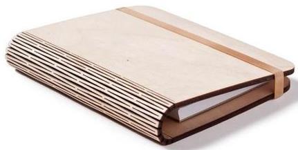
Laser incision is applied successfully in production of so-called “living hinge materials”. These are perforated flat materials with a specific pattern of perforations that allow the material to be bend without breaking. A typical example is a book cover made from plywood modified by perforations (Fig. 1). To improve design of the “living hinge materials”, FENNER (2011) proposed a mathematical model that allowed to reduce the number of trials and errors when designing. It made it possible to create “living hinge materials” fatigue-resistant so they can be used not only for static bends, but also for moving parts of objects.
Fig. 1 Living hinge in book cover made from plywood (LASERCUTCRAFT, s. a.).
The method of incision materials to change their formability can also be applied for spatial forming. The principle of incision is based on creation of two-side perforated grid which allows the material to be bend three-dimensionally. When laser incision, different shapes of perforations are designed (Fig. 2).
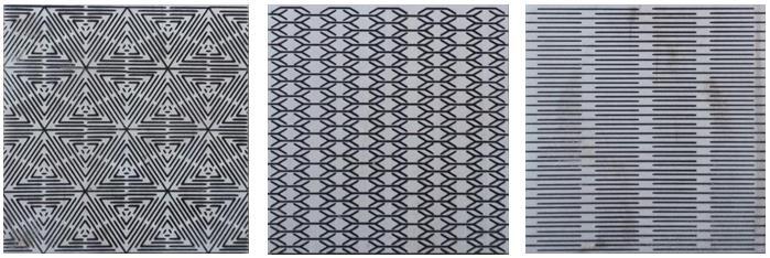
Fig. 2 Perforations used to increase material formability; they also fulfill an aesthetic function (OBRARY, s. a.).
An indisputable advantage of the perforated materials is the reduced weight. Recent interest in reduction the weight of materials is confirmed by the research on properties of lightweight wood materials DUDAS and VILHANOVÁ (2013), VILHANOVÁ and GÁBORÍK (2018), BARBU et al. (2010), EBNER and PETUTSCHNIGG (2005), MEDRI et al. (2015) and other authors.
An important factor affecting the properties of layered materials is the adhesive applied. The most commonly used adhesives for production of layered veneer materials are urea-formaldehyde and phenol-formaldehyde adhesives. Nowadays, when there are increased requirements for the ecological and hygienic safety of products and materials, it is necessary to reduce emissions resulting from applied formaldehyde containing adhesives. One of the possibilities to reduce the emissions from materials and finished products is
modification of the formaldehyde based adhesives. This issue was dealt by LYUTYY et al. (2017), MATYAŠOVSKÝ et al. (2014), RUŽIAK et al. (2017), ŠMIDRIAKOVÁ et al. (2012). Another possibility to reduce formaldehyde emissions is replacing the formaldehyde based adhesives with the adhesives formaldehyde free. At present, also PVAC adhesives are used for production of materials or for finishing materials e.g. veneering. Successful replacement of the formaldehyde based adhesive was reported by SONG et al. (2017). They used a polypropylene foil (PP) as the adhesive for gluing plywood. KAJAKS et al. (2012) used a polyethylene foil (PE). The properties of plywood glued with PE foils was also reported by BEKHTA and SEDLIAČIK (2019), CHANG et al. (2017), IBRAGIMOV et al. (2017),KARRI et al. (2018),FANG, et al. (2013).
The aim of the paper is to evaluate 3D formability of partially perforated materials. The tested materials were veneer based, two layered, with cross layering, glued with polyethylene foils.
MATERIAL AND METHODS
Based on results of veneer formability published by FEKIAČ et al. (2015), sliced veneer of birch (Betula Pendula Roth) was chosen to prepare two-layer material. The thickness of the veneer was 0.58 ± 0.04 mm and the average humidity of 8.5 ± 0.5%. Formats of 90 × 195 mm were cut using CO2 laser; a half of the formats having wood fibres in direction identical to the longer format size and the other half to the shorter format size. A half of the veneer formats was modified by targeted perforations using CO2 laser. The violation of the integrity of the veneer by perforations could increase the deformability of wood.
For the experiments, the perforations in the shape of letter “I“ (line length of 10 mm) and the letter “S” (dimensions of 10 × 5 mm) were designed. The cutting width was 0.5 mm. Three variants of the arrangement of perforations, with respect to wood fibres in the veneer, were designed – parallel to the fibres (marking “P”), perpendicular to the fibres (“K”) and mixed arrangement of both directions (“M”). For each arrangement, two spacing intervals between perforations were designed: 2 mm and 5 mm. The designed perforation variants are shown in Fig. 3.
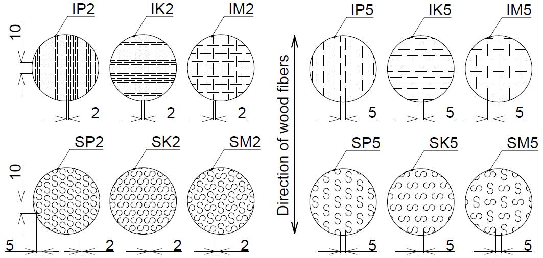
Fig. 3 Variants of perforation on test specimens with respect to wood fibres in veneers; where: I –perforations in shape of letter “I“, S – perforations in shape of letter “S“, P – direction of perforations parallel to wood fibres, K – direction of perforations perpendicular to wood fibres, M – mixed arrangement with respect to wood fibres, 2 – spacing between perforations of 2 mm, 5 – spacing between perforations of 5 mm.
Marking perforation variants as well as marking the test specimens was a combination of letters and a number: the shape of perforation, arrangement of the perforations, spacing between perforations.
The two-layer material for the experimental testing was made from two veneer sheets by cross-laminating. In the glued file, one veneer was modified by perforations and the other was solid (non-perforated). To join the two veneers, low density polyethylene (LDPE) foil with the thickness of 0.12 mm was applied; the dosage was 100 g.m-2. The created assembly was pressed in a heated hydraulic press (FONTIJNE TP 400) under pressing conditions: temperature 150 °C, pressure 1.8 MPa, time 4 minutes. Under the same conditions, the reference material (reference sample)made from solid(non-perforated) veneers was pressed. According to the above mentioned technology, two-layer materials with an average thickness of 1.02 mm and the surface dimensions of 90 × 195 mm were made. After 7 days of conditioning, the weight of each perforated and solid (non-perforated) material was measured using laboratory balance of accuracy of 0.001g. Subsequently, from the prepared materials, test specimens of circular shape with a diameter of 60 mm were cut using a punch (Fig. 3). Nine test specimens were prepared for each variant of perforated material and also for the reference material.
The 3D formability testing was carried out on the principle of pushing the test specimen using a ball punch into a hole in a matrix. The ball with a diameter of 40 mm was moving at speed of 3 mm.min-1 while the circumference of the test specimen was hold. Holding the test specimen prevented curling on perimeter of the test specimen; but at the same time, the specimen could move freely between the matrix and the holder. The testing was proposed and presented in detail by ZEMIAR and FEKIAČ (2014). It is schematically shown in Fig. 4.
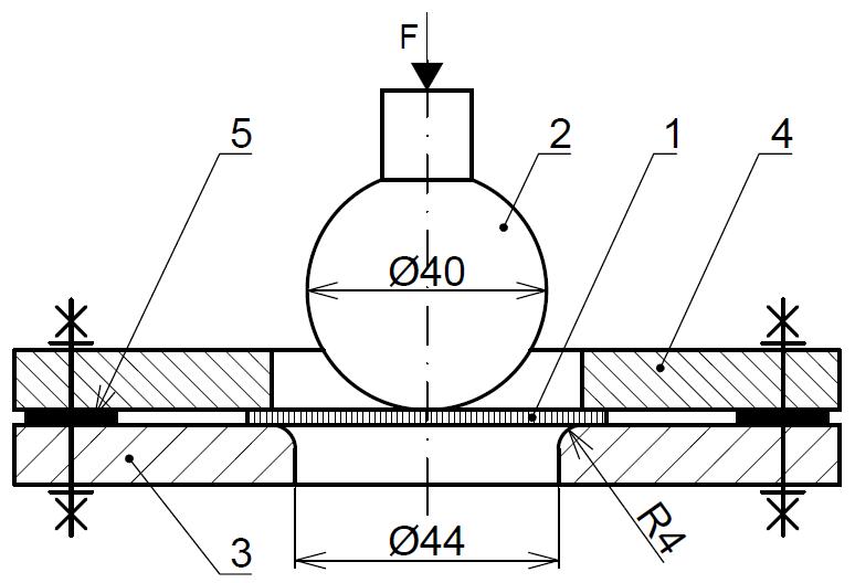
Fig. 4 The testing of 3D formability of veneers using a ball punch – with the specimen hold; where: 1 –test specimen Ø 60 mm, 2 – ball punch, 3 – matrix, 4 – holder, 5 – spacer, F – forming force (loading).
The testing of 3D formability was performed using the test machine LabTest 4.050. The specimens were loaded in two ways with respect to the perforated surface: the perforated surface of the test specimen was loaded by the ball punch (Fig. 5a), or the solid surface was loaded (Fig. 5b).
During the 3D formability testing, the monitored parameters were: the deepening (hmax) and the forming force (F); they were directly recorded by the test machine through integrated sensors. Based on the mentioned parameters, the 3D formability was evaluated.
The main indicator to assess 3D formability was maximal deepening measured (hmax), i.e. deepening at the moment of failure of the test specimen.

Fig. 5 Test specimens loaded during the 3D formability testing: a) on perforated surface, b) on solid surface (non-perforated); where: hmax – maximum deepening at the moment of failure of the specimen, 1 – perforated veneer, 2 – solid veneer, 3 – matrix, 4 – holder, F – forming force (loading).
The additional indicator of 3D formability was the force required to change the shape of the test specimen by per unit of deepening (Fh). The force per unit of deepening (Fh) was calculated as a ratio of the force measured at the moment of failure of the test specimen (Fmax) and the associated deepening (hmax) according to the relation (1):
��ℎ =
�������� ℎ������ (1)
Where: Fh – force per unit of deepening [N.mm-1],
Fmax – the force measured at the moment of failure of the test specimen [N],
hmax – maximum deepening [mm].
The lightening of the material (weight loss) was also monitored; lightening is a result of perforating and is related indirectly to 3D formability. To compare the impact of the variants of perforation on the lightening of the material, percentage of weight reduction was calculated according to the relation (2):
Δ�� =100− ∙100 (2)
Where: ∆m
– lightening of the material [%], mperf – weight of the perforated material [g], mref – weight of the solid (non-perforated) material [g].
RESULTS AND DISCUSSION
The maximum deepening and forces per unit of deepening were evaluated using the program STATISTICA 12 by multi-factor analysis of variance and the Duncan test. Based on significance level (p), the impact of variants of perforation on 3D formability of the tested two-layer materials was assessed. The effect ofperforations on 3D formability was evaluated in view of the shape of perforation, arrangement of perforations with respect to direction of wood fibres in the veneer, spacing between perforations, and direction of loading.
Influence of load direction
The analyses showed that the change in deepening was not significant under loading both the solid and perforated surface for any variant of perforation. This is demonstrated by the Duncan test. The significance level “p” exceeded the standard significance level of 0.05 for each perforation variant.
When designing the perforations, we assumed that the perforation in veneer would allow the material to deform more, without observable breaching. If the perforated veneer in material was on the side loaded by pressure of the punch (Fig. 5a), the perforations would allow the material to be compressed more, without breaching. Conversely, if the perforated veneer was on the opposite side (Fig. 5b), even a slight widening of the perforations would
allow the material to become more deformable. The results indicate that 3D formability was not affected by the positioning of the perforated veneer significantly.
The comparison of measured values of maximum deepening (hmax) depending on the variants of perforation and direction of loading is shown in Fig. 6. The analysis did not confirm better 3D formability of one-side perforated veneer material.
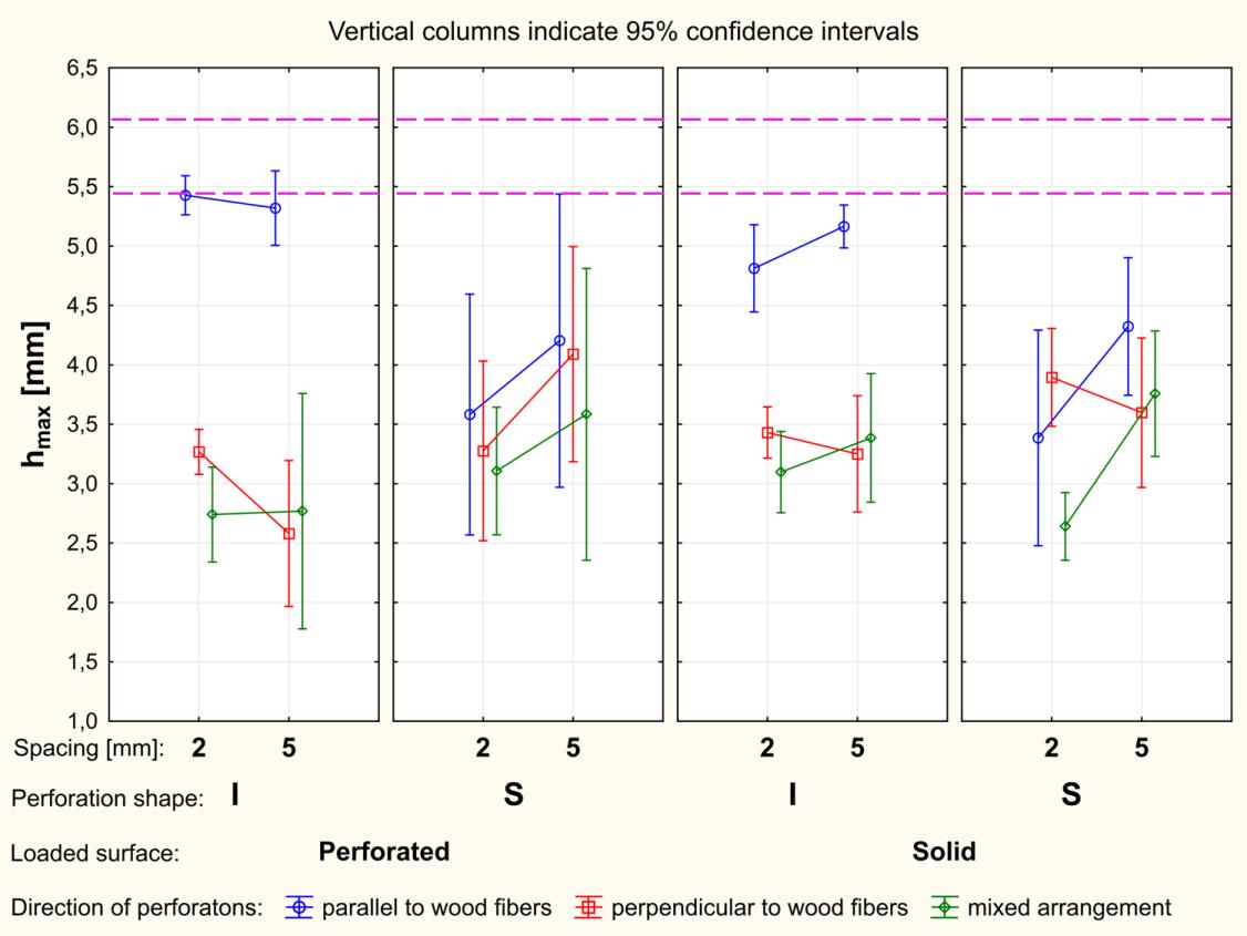
Fig. 6 Deepening (hmax) at loading on solid surface and perforated surfaces; note: I and S – material with perforations in the shape of the letters “I“ or “S“; 2 and 5 – spacing between perforations (mm).
Influence of perforation shape
When evaluating the impact of the shape of perforations on 3D formability, no significant difference between perforations “I” and “S” (except for the perforations parallel to wood fibres) was shown. What was confirmed by Duncan's test.
From the view point of the shape of perforations, it can be stated that the perforations do not affect the 3D formability significantly. However, also other factors must be considered.
Influence of direction of perforations with respect to wood fibres
Comparing the perforation variants in terms direction of perforations, the most noticeable difference in 3D formability was shown in the variants with perforations of “I”.
When comparing the variants with parallel direction of perforations with the variants with perpendicular direction (IP2 with IK2; IP5 with IK5), under load on the perforated surface, the 3D formability of the material with perpendicular perforations was lower by 40 % to 52 %. Under load on the solid surface, the 3D formability of the material with perpendicular perforations was lower by 29 % to 37 %.
The variants with mixed arrangement of perforations (IM2 and IM5), when compared with the parallel arrangement, showed a reduced 3D formability by an average of 35 % under load on the solid surface and by 49 % under load on the perforated surface.
If taking into account the perforation direction, no significant difference was shown between the perforations “S”, except for case (SK2 a SM2 under load on the solid surface).
The difference between the perforation variants “S” varied from 3 to 22 % depending on their direction.
In general, the highest 3D formability was measured for the variants with perforations parallel to wood fibres, lower 3D formability for perforations perpendicular to fibres, and the lowest one for mixed arrangement.
Better 3D formability of the tested materials with perforations parallel to wood fibres can be explained by the fact that these perforations disturb the integrity of the fibres less (less amount of cross-cut fibres) and so weaken the veneer less. This was also confirmed by the measured forces required for 3D forming (Fig. 7). The lowest forces were measured for the variants where the perforations had cut the wood fibres (the arrangement perpendicular to the fibres and the mixed arrangement). The cross-cutting of wood fibres can be a reason why there was no significant difference in 3D formability in “S” perforations (depending on direction of the perforations).
Influence of spacing
The 3D formability tended to increase with increasing spacing between perforations in cases of perforations along the fibers or the mixed arrangement with respect to wood fibres. The 3D formability was in the interval from 1% under load on the perforated surface (variant IM5) to 29.7 % under load on the solid surface (variant SM5).
An opposite tendency was recorded if direction of the perforations was perpendicular to wood fibres; the material with “I” perforations and the spacing of 5 mm (variant IK5) showed smaller deepening (3D formability) by 5.2 % under load on the solid surface than the variant IK2. Under load on the perforated surface, the deepening was lower by 21.1 %.
A possible cause for reduction in 3D formability can be in the perforations themselves as they affect the size of the cross-sectional area of the material and impair the integrity of the material.
Comparison with reference (non-perforated) material
A comparison of deepening measured for perforated two-layer materials with the deepening measured for the reference (non-perforated) material is shown in Fig. 6. The reference specimens reached the deepening of 5.79 mm on average. The range of confidence intervals for the reference specimens is shown by the distance between a pair of pink dashed lines. As can be seen, the perforated test specimens of all the designed perforation variants showed a smaller deepening than the reference specimens. The deepening the most similar to the reference was measured for the specimens with “I” perforations parallel to wood fibres, under load on the perforated surface. The reduction in deepening was by 6.3 % on average (deepening of 5.43 mm) for spacing of 2 mm and by 8.1 % for 5 mm spacing (deepening of 5.32 mm). Under the load on the solid surface, the reduction in 3D formability for the same perforation variant was by 16.9 % for spacing of 2 mm (deepening of 4.81 mm) and by 10.8 % for 5 mm spacing (deepening of 5.17 mm). It can be stated that the expected increasing in 3D formability due to the perforations has not been confirmed.
Force per unit of deepening
The additional indicator of 3D formability was the force per unit of deepening. When evaluating the impact of loading on the solid or the perforated surfaces, the analysis did not confirm significant differences in force per unit of deepening. Evaluation of the measured force per unit of deepening for the individual perforation variants is shown in Fig. 7.
In terms of force per unit of deepening required for 3D forming, the designed perforation variants were positive. When compared to the reference (solid, non-perforated) material, for all the perforated materials, a lower force per unit of deepening was required (ranging from 18.5 % for IP5 to 78.3 % for IK2). The confidence interval of the reference
specimens is defined by the distance between the pink dashed lines (Fig. 7). The average force per unit of deepening for the reference specimens was 71.92 N·mm
1 .
If compared to the reference (non-perforated) material, the most significant decrease in force per unit of deepening was recorded at the perforated variant IK2. If the perforated surface was loaded, the force of 15.7 N·mm 1 was needed; if the solid surface was loaded, the force was 15.6 N·mm 1 . On the other hand, the smallest decrease in the force per unit of deepening was recorded at the variants with “I” perforations parallel to wood fibres. If the perforated surface was loaded, the decrease was by 34 % (force 47.4 N·mm 1) for 2 mm spacing and by 21.2 % (force 56.7 N·mm 1) for 5 mm spacing. If the solid surface was loaded, the decrease was by 34.3 % (force 47.3 N·mm 1) for 2 mm spacing and by 18.5 % (force 58.6 N·mm 1) for 5 mm spacing. The significance of difference between directions of the perforations in the designed variants, what was confirmed by Duncan's test.
The significant difference in the force per unit of deepening was shown between the perforation shapes only if the perforations were parallel and perpendicular to wood fibres
Fig. 7 shows that the force per unit of deepening required for 3D forming of perforation variants with spacing 2 mm was lower by 6.8 % to 34.4 % if compared to 5 mm spacing.
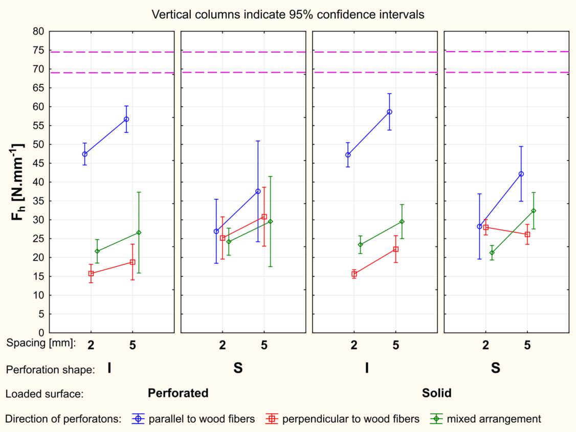
Fig. 7 Force per unit of deepening at loading on solid and perforated surfaces; note: I and S – materials with perforations in the shape of the letters “I“ or “S“; 2 and 5 – spacing between perforations (mm).
Lightening of material
Another change in the material properties due to the perforation was lightening of the material (weight reduction). Depending on designed perforationvariant, different percentage of lightening was achieved (Table 1). No significant weight loss was achieved. The greatest lightening was found for “I” perforations with 2 mm spacing (5.8 %). This was expected, since the mentioned variants have the greatest number of perforations per unit area. If the orientation was perpendicular to wood fibres (variant IK2), the cutting of summer (denser) wood was more frequent which also affected the weight reduction. The slightest lightening was recorded for the materials with “I” perforations with 5 mm spacing (lightening of 1.5 %).
This was also expected, since there were the least number of perforations per unit area (least of all designed variants).
The best formable perforated material “IP2” reached the second largest lightening of 5.1 %, which makes the two-layer material with IP2 perforations very interesting.
Tab. 1 Percentage of lightening of the materials depending on perforation variant.
Lightening [%]
Perforation variant
IP2 IK2 IM2 IP5 IK5 IM5 SP2 SK2 SM2 SP5 SK5 SM5
5.1 5.8 3.3 2.0 1.7 1.5 3.4 3.8 3.3 2.3 2.2 2.1
CONCLUSIONS
The paper is focused on changes in 3D formability of two-layer cross-layered material made from veneers if one of the veneers was perforated. Lightening of the material was also interesting as a secondary benefit of the perforating. Based on the experimental results, the following conclusions can be stated: 1. The 3D formability of the materials with perforations in the shape of the letter “I” oriented in direction parallel to wood fibres (perforation variants IP2 and IP5), was the most similar to the material with no perforation. 2. The best 3D formability was recorded for the materials with perforations oriented parallel to wood fibres, followed by the materials with perforations perpendicular to fibres and then materials with mixed arrangements of the perforations. 3. Almost all the designed perforation variants showed better 3D formability at 5 mm spacing if compared to 2 mm spacing (by 1 % to 29.7%). 4. No effect of the shape of perforations on 3D formability was shown (excluding the perforations parallel to wood fibres. 5. If compared with the reference (solid, non-perforated) material, none of the designed perforated materials showed increased 3D formability. 6. The force recalculated per unit of deepening was lower for all the designed perforation variants (from 18.5 % to 78.3 %) if compared to the force per unit of deepening for the reference (solid non-perforated) material. 7. In terms of lightening of material, the perforation variant with “I” perforations perpendicular to wood fibres and spacing of 2 mm was the most significant; the material lightening was 5.8 %.
REFERENCES
BARBU, M., LÜDTKE, J., THÖMEN, H., WELLING, J. 2010. New technology for the continuous production of wood-based lightweight panels. In Proceedings of the International Convention of Society of Wood Science and Technology and United Nations Economic Commission for Europe –Timber Committee. Switzerland: Geneva, 1114 October 2010, Paper IW-1, 10 s. BEKHTA, P., SEDLIAČIK, J. 2019. Enviromentally-friendly high-density polyethylene-bonded plywood panels. In Polymers, 2019, Vol. 11, No. 7, pp. 1166. BUCHELT, B., SCHEIDING, W., EICHELBERGER, K. 2010. Entwicklung einer Verfahrenstechnologie zur Herstellung von thermisch modifiziertem Furnier für hochwertige Anwendungen unter Berücksichtigung der Umformbarkeit. [online]. [cit. 2010-12-20]. Available online: <http://nbnresolving.de/urn:nbn:de:bsz:14-qucosa-63542> .
CHANG,L.,GUO,W.,QIHENG,T.2017.Assessing the Tensile Shear Strength and Interfacial Bonding Mechanism of Poplar Plywood with High-density Polyethylene Films as Adhesive. In Bioresources, 2017, Vol. 12, No. 1, pp. 571585. DUDAS,J.,VILHANOVÁ,A. 2013. Sozdanije oblegčennoj fanery dľa konkretnych celej. In Annals of Warsaw University of Life Sciences, 2013, No. 82, pp. 235241. DUKTA. [s. a.]. Dukta flexible wood. [online]. [cit. 2019-05-20]. Available online: <https://dukta.com/en/> . EBNER, M., PETUTSCHNIGG. A. J. 2005. Lightweight constructions-paper materials as a new option to build furniture. In Proceeding International Scientific Conference Interior and Furniture Design. Sofia: University of Forestry, 1718 October 2005, s. 119131. FANG,L.,CHANG,L.,GUO,W.,CHEN,Y.,WANG,Z.2013. Manufacture of Environmentally Friendly Plywood Bonded with Plastic Film. In Forest Products Journal, 2013, Vol. 63, No. 78, pp. 283287. FEKIAČ,J.,GÁBORÍK,J.,ŠMIDRIAKOVÁ,M. 2016. 3D formability of moistened and steamed veneers. In Acta Facultatis Xylologiae Zvolen, 2016, Vol. 58, No. 2 , pp. 1526. FEKIAČ,J., ZEMIAR,J.,GAFF,M.,GÁBORÍK,J.,GAŠPARÍK,M.,MARUŠÁK,R. 2015. 3D-moldability of veneers plasticized with water and ammonia. In BioResources, 2015, Vol. 10, No. 1, pp. 866-876. FENNER, P. 2011. Laser-cut Lattice Living Hinges. [online]. [cit. 2019-05-20]. Available online: <https://www.defproc.co.uk/blog/2011/laser-cut-lattice-living-hinges/#more-1916>. GAFF, M., KAČÍK, F., DOMLJAN, D., VONDROVA, V., BABIAK, M. 2017. Bendability of thermally modified oak. In 28th International Conference on Wood Science and Technology 2017: Implementation of Wood Science in Woodworking Sector. Zagreb: University of Zagreb – Faculty of Forestry, 2017, pp. 143151. HEROLD, N., PFRIEM, A. 2013. Impregnation of veneer with furfuryl alcohol for an improved plasticization and moulding. In European Journal of Wood and Wood Products, 2013, Vol. 71, issue 2, pp 281282. IBRAGIMOV, A., VASILKIN, A., FEDOTOV, A. 2017. Research physic-mechanical properties of composite materials on the base of peeled veneer and low density polyethylene. In IOP Conference Series: Earth and Environmental Science. 2017, 5 s. KAJAKS, J., REIHMANE, S., GRINBERGS, U., KALNINS, K. 2012. Use of innovative environmentally friendly adhesives for wood veneer bonding. In Proceedings of the Estonian Academy of Sciences, 2012, Vol. 61, Issue 3, pp 207211. KARRI,R.,MOHANTY,B.N.,DUBEY,M.K. 2018. Bond Quality, Mechanical and Physical Properties of Wood – Polyethylene Reinforced Plywood. In International Journal of Engineering Innovation & Research, 2018, Vol. 7, Issue 5, pp. 236–239. KRENZ, S. 2013. Reholz - Marktführer in 3D-Furnier: Furnier in der 3.Dimension. [online]. [cit. 2013-07-13]. Available online: <https://tu-dresden.de/ressourcen/dateien/forschung/wissens_und_technologietransfer/ dresdner_transferbrief/archivordner/Ausgabe03_05/DTB_3.05_20.pdf?lang=en>. LASERCUTCRAFTS. [s. a.]. Personalized “Living Hinge“ Note Books. [online]. [cit. 2019-06-17]. Available online: <https://lasercutcrafts.com.au/products/personalized-living-hinge-note-books>. LYUTYY, P., BEKHTA, P., ORTYNSKA, G., SEDLIAČIK, J. 2017. Formaldehyde, phenol and ammonia emissions from wood/recycled polyethylene composites. In Acta Facultatis Xylologiae Zvolen, 2017, Vol. 59, No. 1, pp. 107112.
MATYAŠOVSKÝ, J., SEDLIAČIK, J., MATYAŠOVSKÝ, J., Jr., JURKOVIČ, P., DUCHOVIČ, P. 2014. Collagent and keratin colloid systems with a multifunctional effect for cosmetic and technical applications. In Journal of the American Leather Chemists Association, 2014, Vol. 109, No. 9, pp. 284-295. MEDRI,V.,PAPA,E.,MAZZOCCHI,M.,LAGHI,L.,MORGANTI,M.,FRANCISCONI,J.,LANDI,E. 2015. Produktion and characterization of lightweight. In Materials and Design, 2015,Vol. 85,pp. 266274. NAVI, P., SANDBERG, D. 2012. Thermo-hydro-mechanical processing of wood. CRC Press, 2012. 360 s. ISBN 978-1-4398-6042-7. OBRARY. [s. a.]. Living Hinge Swatches. [online]. [cit. 2019-05-20]. Available online: <https://obrary.com/products/living-hinge-patterns?variant=798259727>.
ROSENTHAL, M. 2009. Entwicklung eines biologisch inspirierten, dreidimensional verformbaren Furniers aus Druckholz: Dissertation von der Fakultät Maschinenwesen der Technischen Universität Dresden. [online]. [cit. 2019-08-19]. Available online: <http://nbn-resolving.de/urn:nbn:de:bsz:14qucosa-22891>. RUŽIAK, I., IGAZ, R., KRIŠŤÁK, Ľ., RÉH, R., MITTERPACH, J., OČKAJOVÁ, A., KUČERKA, M. 2017. Influence of urea-formaldehyde adhesive modification with beech bark on chosen properties of plywood. In BioResources, 2017, Vol. 12, No. 2, pp. 3250-3264. SLABEJOVÁ, G., LANGOVÁ, N., DEÁKOVÁ, V. 2017. Influence of silicone resin modification on veneer tensile strength and deformation. In Acta Facultatis Xylologiae Zvolen, 2017, Vol. 59, No. 1, pp. 4147. SLABEJOVÁ, G., ŠMIDRIAKOVÁ, M. 2013. Modifikácia bukových dýh silikónovými živicami za účelom ich 3D tvárnenia. In Pokroky vo výrobe a použití lepidiel v drevopriemysle: XXI. Symposium. Zvolen: Technická univerzita vo Zvolene, 2013, pp. 5964. SLABEJOVÁ, G., ŠMIDRIAKOVÁ, M. 2014. Influence of modification of veneers on 3D - forming. In Annals of Warsaw University of Life Sciences, 2014, No. 85 pp. 226229. SONG, W., WEI, W., LI, X., ZHANG, S. 2017. Utilization of Polypropylene Film as an Adhesive to Prepare Formaldehyde-free, Weather-resistant Plywood-Evaluation, and Interface Modification. In Bioresources, 2017, Vol. 12, No. 1, pp. 228254. ŠMIDRIAKOVÁ, M., SEDLIAČIK, J., JABŁOŃSKI, M., KRAJEWSKI, K. J. 2012. Use of tanned leather waste for modification of urea-formaldehyde adhesives. In Przemysl Chemiczny, 2012, Vol. 91, Issue 11, pp. 21922195. VILHANOVÁ, A., GÁBORÍK, J. 2018. Vplyv zníženia hmotnosti preglejovanej dosky na mechanické vlastnosti. In Nábytok a výrobky z dreva 2018. Zvolen: Technická univerzita vo Zvolene, 2018, pp. 6165. WAGENFÜHR, A., BUCHELT, B., PFRIEM, A. 2006. Material behaviour of veneer during multi dimensional moulding. In Holz als Roh- und Werkstoff, 2006. Vol. 64, No. 2, pp. 83–89. ZEMIAR,J.,FEKIAČ,J.2014. Skúšanie a hodnotenie 3D -tvárnosti dýh. In Acta Facultatis Xylologiae Zvolen, 2014, Vol. 56, No. 1, pp. 3138.
ACKNOWLEDGEMENT
This work was supported by Slovak Research and Development Agency under the contract No. APVV-18-0378, APVV-14-0506, and APVV-16-0177, and by the Scientific Grant Agency of the Ministry of Education SR Grant No. VEGA 1/0556/19. This publication was supported by the Operational Programme ‘Research and Innovation’, the project: LIGNOPRO -Progresívny výskum úžitkových vlastností materiálov a výrobkov na báze dreva (Progressive Research into Utility Properties of Materials and Products Based on Wood), ITMS project code: 313011T720, co-funded by the European Regional Development Fund (ERDF).
AUTHORS' ADDRESS
Ing. Jozef Fekiač, PhD. doc. Ing. Jozef Gáborík, CSc. Ing. Mária Šmidriaková, PhD. Technical University in Zvolen Faculty of Wood Sciences and Technology Department of Furniture and Wood Products T. G. Masaryka 24 960 01 Zvolen, Slovakia jozef.fekiac@tuzvo.sk gaborik@tuzvo.sk smidriakova@tuzvo.sk
66


